

Page 1

UNISTAR SB-NET
120-230V 50/60Hz
800VA to 3kVA
USER MANUAL
003-2594 REV B
Page 2

Staco Energy is highly specialized in the development and production of uninterruptible power
systems (UPS). The UPS’s of this series are high quality products, carefully designed and
manufactured to ensure optimum performance.
No reproduction of any part of this manual, even partial, is permitted without the authorization of Staco
Energy Products Company. The Staco Energy Products Company reserves the right to modify the
product described herein, in order to improve it, at any time and without notice.
Page | ii
Page 3

Table of Contents
1. Important Safety Warnings ................................................................................................................... 1
1.1 Transportation ................................................................................................................................ 1
1.2 Preparation ..................................................................................................................................... 1
1.3 Installation ...................................................................................................................................... 1
1.4 Operation ....................................................................................................................................... 1
1.5 Maintenance, Service and Faults .................................................................................................... 2
1.6 WEEE ............................................................................................................................................. 3
1.7 FCC (120V Models) ........................................................................................................................ 3
1.8 EMC (230V Models) ....................................................................................................................... 3
2. Installation and setup ........................................................................................................................... 4
2.1 120V Models Rear panel view ........................................................................................................ 4
2.1.1 800VA/1.1KVA/1.5KVA............................................................................................................. 4
2.1.2 2 kVA ....................................................................................................................................... 4
2.1.3 3 kVA ....................................................................................................................................... 4
2.2 230V Models Rear panel view ........................................................................................................ 5
2.2.1 800VA/1.1KVA/1.5KVA............................................................................................................. 5
2.2.2 2 kVA ....................................................................................................................................... 5
2.2.3 3 kVA ....................................................................................................................................... 5
2.3 Operating principle ......................................................................................................................... 6
2.4 Install the UPS ................................................................................................................................ 6
2.4.1 Rack-mount Installation ........................................................................................................... 7
2.4.2 Tower Installation ..................................................................................................................... 7
2.5 Setup the UPS ................................................................................................................................ 8
2.6 Battery Replacement .................................................................................................................... 10
2.7 Battery Kit Assembly (option) ......................................................................................................... 11
3. Operation ........................................................................................................................................... 13
3.1 Button operation ........................................................................................................................... 13
3.2 LCD Panel .................................................................................................................................... 14
3.3 Audible Alarm ............................................................................................................................... 15
3.4 LCD display wordings index ......................................................................................................... 15
3.5 UPS Settings ................................................................................................................................ 16
3.6 Steps for setting programmable outlet .......................................................................................... 18
3.7 Operating Mode Description ......................................................................................................... 19
3.8 Faults Reference Code ................................................................................................................. 20
3.9 Warning indicator .......................................................................................................................... 20
4. Troubleshooting .................................................................................................................................. 21
5. Storage and Maintenance .................................................................................................................. 22
5.1 Operation ..................................................................................................................................... 22
5.2 Storage ......................................................................................................................................... 22
6. UPS Specifications ............................................................................................................................. 23
6.1 120V Models .................................................................................................................................... 23
6.2 230V Models .................................................................................................................................... 24
Page | iii
Page 4

1. Important Safety Warnings
Please comply with all warnings and operating instructions in this manual strictly. Save this manual properly
and read carefully the following instructions before installing the unit. Do not operate this unit before reading
through all safety information and operating instructions carefully
1.1 Transportation
Please transport the UPS system only in the original package to protect against shock and impact.
1.2 Preparation
Condensation may occur if the UPS system is moved directly from cold to warm environment. The UPS
system must be absolutely dry before being installed. Please allow at least two hours for the UPS
system to acclimate the environment.
Do not install the UPS system near water or in moist environments.
Do not install the UPS system where it would be exposed to direct sunlight or near heater.
Do not block ventilation holes in the UPS housing.
1.3 Installation
Do not connect appliances or devices which would overload the UPS system (e.g. laser printers) to the
UPS output sockets.
Place cables in such a way that no one can step on or trip over them.
Do not connect domestic appliances such as hair dryers to UPS output sockets.
The UPS can be operated by any individuals with no previous experience.
Connect the UPS system only to an earthed shockproof outlet which must be easily accessible and
close to the UPS system.
Please use only VDE-tested, CE-marked mains cable (e.g. the mains cable of your computer) to
connect the UPS system to the building wiring outlet (shockproof outlet).
Please use only VDE-tested, CE-marked power cables to connect the loads to the UPS system.
When installing the equipment, it should ensure that the sum of the leakage current of the UPS and the
connected devices does not exceed 3.5mA.
Temperature Rating - Units are considered acceptable for use in a maximum ambient of 40°C (104°F).
For PLUGGABLE EQUIPMENT, the socket-outlet shall be installed near the equipment and shall be
easily accessible.
CAUTION: The unit is heavy. Lifting the unit requires a minimum of two people.
Check if there is a protection device against over current and short circuit in the upstream of the UPS
system. The recommended protection spec is 11A for 800VA~1100VA, 15A for1.5KVA, 20A for LV
2KVA and 30A for 2.5~3KVA with a B or C trip curve.
1.4 Operation
Do not disconnect the mains cable on the UPS system or the building wiring outlet (shockproof socket
outlet) during operations since this would cancel the protective earthing of the UPS system and of all
connected loads.
The UPS system features its own, internal current source (batteries). The UPS output sockets or output
terminals block may be electrically live even if the UPS system is not connected to the building wiring
outlet.
In order to fully disconnect the UPS system, first press the OFF/Enter button to disconnect the mains.
Prevent no fluids or other foreign objects from inside of the UPS system.
The EPO, RS-232 and USB circuits are an IEC 60950-1 safety extra low voltage (SELV) circuit. This
circuit must be separated from any hazardous voltage circuits by reinforced insulation.
Page | 1
Page 5

Manufacture
Type
Rated
Toplite (Guangzhou) Technology
Battery Co Ltd (MH29104)
NPW45-12
12 V dc, 9.0 Ah
UXW460-12
12 V dc, 9.0 Ah
NPW36-12
12 V dc, 7.2 Ah
UXW360-12
12 V dc, 7.2 Ah
NPW45-12 FR
12 V dc, 7.0 Ah
UXW460-12/FR
12 V dc, 7.0 Ah
NPW36-12 FR
12 V dc, 7.0 Ah
UXW360-12/FR
12 V dc, 7.0 Ah
CSB Battery Co Ltd (MH14533)
UPS 12460 F2
12 V dc, 9.0 Ah
UPS 12360 6
12 V dc, 6.5 Ah
UPS 12360 7
12 V dc, 6.5 Ah
HR 1234W
12 V dc, 8.5 Ah
HR 1234W FR
12 V dc, 8.5 Ah
Yuasa Battery (Guangdong) Co
Ltd (MH29616)
NPW45-12
12 V dc, 8.0 Ah
NPW45-12FR
12 V dc, 8.0 Ah
1.5 Maintenance, Service and Faults
The UPS system operates with hazardous voltages. Repairs may be carried out only by qualified
maintenance personnel.
Caution - risk of electric shock. Even after the unit is disconnected from the mains (building wiring
outlet), components inside the UPS system are still connected to the battery and electrically live and
dangerous.
Before carrying out any kind of service and/or maintenance, disconnect the batteries and verify that no
current is present and no hazardous voltage exists in the terminals of high capability capacitor such as
BUS-capacitors.
To avoid electrical shock, turn off the unit and unplug it form the AC power source before servicing the
battery
Only persons who are adequately familiar with batteries and with the required precautionary measures
may replace batteries and supervise operations. Unauthorized persons must be kept well away from
the batteries.
Caution - risk of electric shock. The battery circuit is not isolated from the input voltage. Hazardous
voltages may occur between the battery terminals and the ground. Before touching, please verify that
no voltage is present!
Batteries may cause electric shock and have a high short-circuit current. Please take the precautionary
measures specified below and any other measures necessary when working with batteries:
-remove wristwatches, rings and other metal objects
-use only tools with insulated grips and handles.
When changing batteries, install the same number and same type of batteries.
Do not attempt to dispose of batteries by burning them. This could cause battery explosion.
Do not open or destroy batteries. Escaping electrolyte can cause injury to the skin and eyes. It may be
toxic.
When replacing batteries, use the same type and number of batteries or battery packs.
Page | 2
Page 6

Do not dismantle the UPS system.
A battery can may cause a risk of electrical shock and high short-circuit current. The
following precautions should be observed when working on batteries:
a) Remove watches, rings, or other metal objects.
b) Use tools with insulated handles.
c) Wear rubber gloves and boots.
d) Do not lay tools or metal parts on top of batteries.
e) Disconnect charging source prior to connecting or disconnecting battery terminals.
f) Determine if battery is inadvertently grounded. If inadvertently grounded, remove source
from ground. Contact with any part of a grounded battery can result in electrical shock.
The likelihood of such shock can be reduced if such grounds are removed during
installation and maintenance.
1.6 WEEE
Information for Protection of the Equipment
UPS SERVICING – This UPS and batteries makes use of components dangerous for the enviroment
(electronic cards, electronic components). The components removed must be taken to specialized
collection and disposal centers.
Notice to European Union Customers: Disposal of Old Appliances – This product has been
supplied rom an enviromentally aware manufacturer that complies with Waste Electrical and Electrnic
Equipment (WEEE) Directive 2002/96/CE. The ”crossed-out wheelie bin” symbol at right is placed on this
product to encourage you to recycle wherever possible. Please be environmentally responsible and
recycle this product through your recycling facility at its end of life. Do not dispose of this product as
unsorted municipal waste. Follow locla municipal waste ordinances for proper disposal provisions to
reduce the environmental impact to waste ectrical and electronic equipment (WEEE)
1.7 FCC (120V Models)
NOTE: This equipment has been tested and found to comply with the limits for a Class A digital device,
pursuant to part 15 of the FCC Rules. These limits are designed to provide reasonable protection against
harmful interference when the equipment is operated in a commercial environment. This equipment
generates, uses, and can radiate radio frequency energy and, if not installed and used in accordance
with the instruction manual, may cause harmful interference to radio communications. Operation of this
equipment in a residential area is likely to cause harmful interference in which case the user will be
required to correct the interference at his own expense.
1.8 EMC (230V Models)
WARNING: This is a category C2 UPS product. In a residential environment, this product may cause
radio interference, in which case the user may be required to take additional measures.
Page | 3
Page 7
2. Installation and setup
kVA
Input
Connection
Output
Connection
800VA/1.1KVA/1.5KVA
5-15P
5-15R
2kVA
5-20P
5-20R
3 kVA
L5-30P
5-20R & L5-30R
NOTE: Before installation, please inspect the unit. Be sure that nothing inside the package is damaged.
Please keep the original package in a safe place for future use.
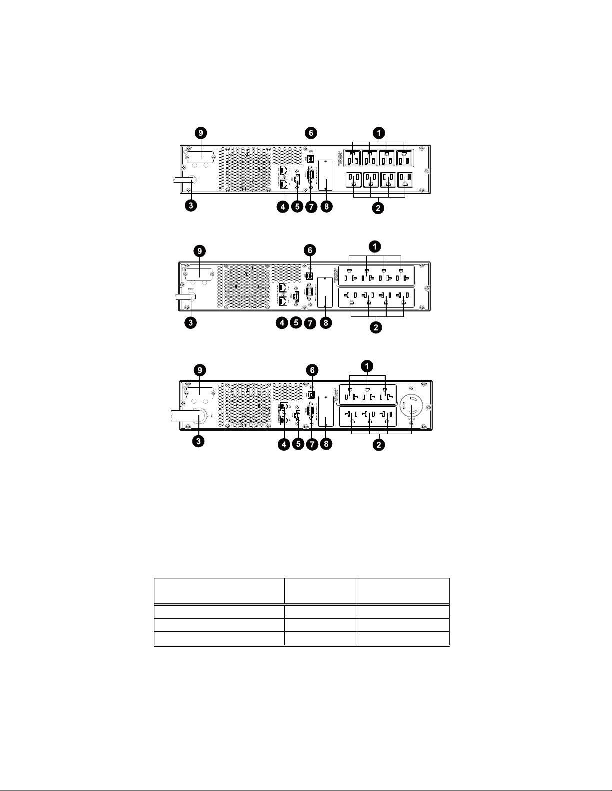
2.1 120V Models Rear panel view
2.1.1 800VA/1.1KVA/1.5KVA
2.1.2 2 kVA
2.1.3 3 kVA
1. Programmable outlets: connect to non-critical loads.
2. Output receptacles: connect to mission-critical loads.
3. AC input
4. Network/Fax/Modem surge protection
5. Emergency power off function connector (EPO)
6. USB communication port
7. RS-232 communication port
8. SNMP intelligent slot
9. External battery connector
Table 1 – Input/Output Connections
Page | 4
Page 8

2.2 230V Models Rear panel view
kVA
UPS Input
Connection
UPS Output
Connection
Input Cord
Connector
800VA/1.1KVA/1.5KVA
IEC320-C14
IEC320-C13
C13
2kVA
IEC320-C20
IEC320-C13
C19
3kVA
IEC320-C20
IEC320-C13 & IEC320-C19
C19
2.2.1 800VA/1.1KVA/1.5KVA
2.2.2 2 kVA
2.2.3 3 kVA
1. Programmable outlets: connect to non-critical loads.
2. Output receptacles: connect to mission-critical loads.
3. AC input
4. Network/Fax/Modem surge protection
5. Emergency power off function connector (EPO)
6. USB communication port
7. RS-232 communication port
8. SNMP intelligent slot
9. External battery connector
Table 2 – Input/Output Connections
Page | 5
Page 9
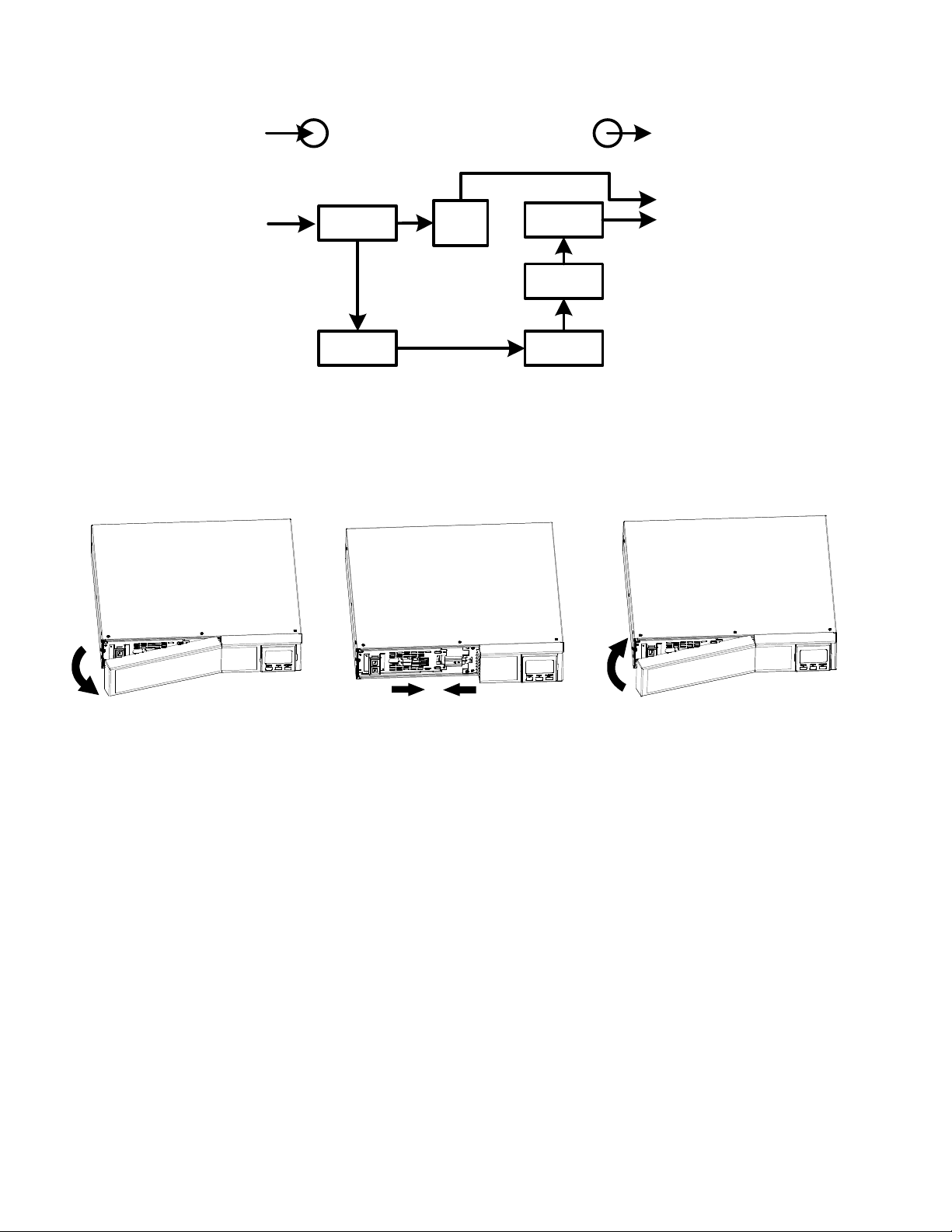
2.3 Operating principle
EMI/RFI
Filters
Battery
Charger
Battery
DC-to-DC
Converter
Inverter
AVR
TX
Output
The UPS is composed of mains input, EMI/RFI Filters, Inverter, Battery charger, DC-to-DC converter,
battery, AVR TX and UPS output
2.4 Install the UPS
For safety consideration, the UPS is shipped out from factory without connecting battery wires. Before
installing the UPS, please follow the below steps to re-connect battery wire.
Step 1 Step 2 Step 3
Step 1: Remove front panel.
Step 2: Remove battery panel and re-connect battery wire.
Step 3: Put battery panel and cover back to the unit.
This UPS can be either displayed on the desk or mounted in the 19” rack chassis. Please choose proper
installation to position this UPS.
Page | 6
Page 10

2.4.1 Rack-mount Installation
CAUTION – Do NOT use the mounting brackets to lift the unit. The mounting brackets are only for securing
the unit to the rack.
Install UPS alone
Install UPS and external battery
2.4.2 Tower Installation
Install UPS alone
Install UPS and external battery
NOTE: When installing the UPS or battery pack with feet, keep 2.76in distance from the edge of the unit.
Page | 7
Page 11

2.5 Setup the UPS
Step 1: UPS input connection
Plug the UPS into a two-pole, three-wire, grounded receptacle only. Avoid using extension cords.
Step 2: UPS output connection
There two kinds of outputs: programmable outlets and general outlets. Connect non-critical devices to
the programmable outlets and critical devices to the general outlets. During power failure, you may
extend the backup time to critical devices by setting shorter backup time for non-critical devices.
Step 3: Communication connection
Communication port:
USB port RS-232 port Intelligent slot
To allow for unattended UPS shutdown/start-up and status monitoring, connect one end of the
communication cable to the USB/RS-232 port and the other end to the communication port of your PC.
With the monitoring software installed, you can perform these operations:
Remote Shutdown of UPS
Send shutdown commands to remote computers
Remotely set parameters of the UPS
Set-up the number of battery strings connected
Set-up voltage and frequency ranges
See manual for monitoring software for details.
The UPS is equipped with an intelligent slot perfect for either a SNMP or an AS400 card. Installing either
a SNMP or AS400 card in the UPS will provide advanced communication and monitoring options.
NOTE: USB port and RS-232 port can’t work at the same time.
Step 4: Network connection
Network/Fax/Phone surge port
Connect a single modem/phone/fax line into surge-protected “IN” outlet on the back panel of the UPS
unit. Connect from “OUT” outlet to the equipment with another modem/fax/phone line cable.
Page | 8
Page 12

Step 5: Disable and enable EPO function
External Battery Pack
External Battery Pack
UPS
This UPS is equipped with EPO function. By default, the UPS is delivered from factory with Pin 1 and pin
2 closed (a metal plate is connected to Pin 1 and Pin2) for UPS normal operation. To activate EPO
function, remove two screws on EPO port and green connector will be removed.
Note: The EPO function logic can be set up via LCD setting. Please refer to program 16 in UPS setting
for the details.
Step 6: External battery connection
Connect one end of external battery cable to UPS unit and the other end to battery pack. See below
chart for detailed connection.
CAUTION: Connection to External Battery shall be installed by SERVICE PERSONNEL only.
CAUTION – Risk of fire hazard.
Step 7: Turn on the UPS
Press the ON/Mute button on the front panel for two seconds to power on the UPS.
Note: The battery charges fully during the first five hours of normal operation. Do not expect full battery
run capability during this initial charge period.
Step 8: Install software
Install UPS monitoring software to fully configure UPS shutdown. Follow the steps below to download
and install monitoring software:
1. Go to the website http://www.power-software-download.com
2. Click ViewPower software icon and then choose your required OS to download the software.
3. Follow the on-screen instructions to install the software.
4. When your computer restarts, the monitoring software will appear as an orange plug icon located in
the system tray, near the clock.
Page | 9
Page 13

2.6 Battery Replacement
NOTICE: This UPS is equipped with internal batteries and only service personnel can replace the
batteries.
CAUTION!! Consider all warnings, cautions, and notes before replacing batteries.
NOTE: Upon battery disconnection, equipment is not protected from power outages.
Step 1 Step 2 Step 3
Step 4 Step 5 Step 6
Step Step 7
Step 1: Remove front panel.
Step 2: Disconnect battery wire and remove battery panel.
Step 3: Pull out the battery box.
Step 4: Remove the top cover of battery box and replace the inside batteries.
Step 5: After replacing the batteries, put the battery box back to original location and screw in tightly.
Step 6: Re-connect the battery wire and screw battery panel back on the unit.
Step 7: Put the front panel back on the unit.
Page | 10
Page 14
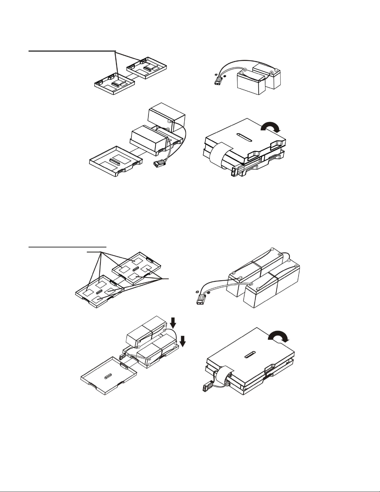
2.7 Battery Kit Assembly (option)
NOTICE: Replacement battery pack comes fully assembled from the factory. Consult factory for details.
2-battery kit – 800-1000VA
Step 1 Step 2
Step 3 Step 4
Step 1: Remove adhesive tapes.
Step 2: Connect all battery terminals by following below picture.
Step 3: Put assembled battery packs on one side of plastic shells.
Step 4: Cover the other side of plastic shell as shown below. Then, battery kit is fully assembled.
4-battery kit – 1.5-2kVA
Step 1 Step 2
Step 3 Step 4
Step 1: Remove adhesive tapes.
Step 2: Connect all battery terminals by following below picture.
Step 3: Put assembled battery packs on one side of plastic shells.
Step 4: Cover the other side of plastic shell as shown below. Then, battery kit is fully assembled.
Page | 11
Page 15

6-battery kit – 2.5-3kVA
Step 1 Step 2
Step 3 Step 4
Step 1: Remove adhesive tapes.
Step 2: Connect all battery terminals by following below picture.
Step 3: Put assembled battery packs on one side of plastic shells.
Step 4: Cover the other side of plastic shell as shown below. Then, battery kit is fully assembled.
Page | 12
Page 16

3. Operation
Button
Function
ON/Mute Button
Turn on the UPS: Press and hold ON/Mute button for at least 2 seconds to
turn on the UPS.
Mute the alarm: After the UPS is turned on in battery mode, press and hold
this button for at least 3 seconds to disable or enable the alarm system. But
it’s not applied to the situations when warnings or errors occur.
Up key: Press this button to display previous selection in UPS setting
mode.
Switch to UPS self-test mode: Press and hold ON/Mute button for 3
seconds to enter UPS self-testing while in AC mode
OFF/Enter Button
Turn off the UPS: Press and hold this button at least 2 seconds to turn off
the UPS
Confirm selection key: Press this button to confirm selection in UPS setting
mode.
Select Button
Switch LCD message: Press this button to change the LCD message for
input voltage, input frequency, battery voltage, output voltage and output
frequency.
Setting mode: Press and hold this button for 3 seconds to enter UPS
setting mode when UPS is off.
Down key: Press this button to display next selection in UPS setting mode.
ON/Mute + Select
Button
Rack or Tower display switch: Press Select and OFF/Enter buttons
simultaneously for 3 seconds. The display change from/to Rack to/from
Tower.
3.1 Button operation
Button View
Page | 13
Page 17
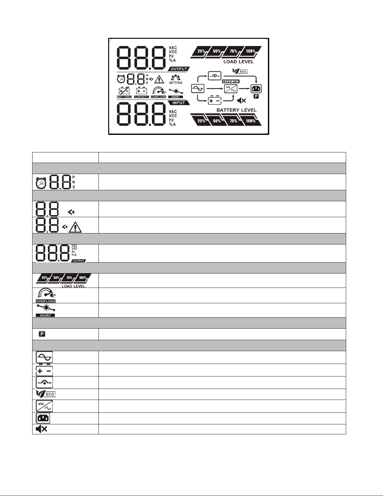
3.2 LCD Panel
Display
Function
Backup time information
Indicates the estimated backup time.
H: hours, M: minute
Configuration and fault information
Indicates the configuration items, and the configuration items are listed in
details in section 3-5.
Indicates the warning and fault codes, and the codes are listed in details in
section 3-7 and 3-8.
Output information
Indicates the output voltage and output frequency.
V: voltage, Hz: frequency
Load information
Indicates the load level by 0-24%, 25-49%, 50-74%, and 75-100%.
Indicates overload.
Indicates the load or the UPS output is short circuited.
Programmable outlets information
Indicates that programmable management outlets are working.
Mode operation information
Indicates the UPS connects to the mains.
Indicates the battery is working.
Indicates the bypass circuit is working.
Indicates the ECO mode is enabled.
Indicates the inverter circuit is working.
Indicates the output is working.
Indicates that the UPS alarm is disabled.
Page | 14
Page 18

Battery information
Indicates the Battery level by 0-24%, 25-49%, 50-74%, and 75-100%.
Indicates the battery is fault.
Indicates low battery level and low battery voltage.
Input & Battery voltage information
Indicates the input voltage, input frequency and battery voltage. Vac: Input
voltage, Vdc: battery voltage, Hz: input frequency
Battery Mode
Sounding every 10 seconds
Low Battery
Sounding every 2 seconds
Overload
Sounding every second
Fault
Continuously sounding
Abbreviation
Display content
Meaning
ENA
Enable
DIS
Disable
ESC
Escape
ON ON
OK
OK
EP
EPO
AO Active open
AC Active close
TP Temperature
CH Charger
RAC
Rack display
TOE
Tower display
SF
Site Fault
EE
EEPROM error
BR Battery Replacement
3.3 Audible Alarm
3.4 LCD display wordings index
Page | 15
Page 19

3.5 UPS Settings
Parameter 3
Parameter 1
Parameter 2
There are three parameters to set up the UPS.
Parameter 1: Program alternatives. Refer to below table.
Parameter 2 and Parameter 3 are the setting options or values
for each program.
Interface
Setting
For 110/115/120/127 VAC models:
110: presents output voltage is 110Vac
115: presents output voltage is 115Vac
120: presents output voltage is 120Vac (Default)
127: presents output voltage is 127Vac
For 208/220/230/240 VAC models:
208: presents output voltage is 208Vac
220: presents output voltage is 220Vac
230: presents output voltage is 230Vac
(Default)
240: presents output voltage is 240Vac
Interface
Setting
ENA: Programmable outlets enable (Default)
DIS: Programmable outlets disable
Interface
Setting
Setting the backup time limits in minutes from 0-999 for
programmable outlets which connect to non-critical devices on
battery mode.
01: Output voltage setting
02: Programmable outlets enable/disable
03: Programmable outlets setting
Page | 16
Page 20

04: Maximum charger current setting
Interface
Setting
Set up the maximum charger current.
1/2/4/6/8: setting the maximum charger current at 1/2/4/6/8
Ampere. (Default: 8A)
Note: This setting is only effective for super charger.
Interface
Setting
Parameter 2: Set up backup time on battery mode for general
outlets.
0-999: setting the backup time in minutes from 0-999 for general
outlets on battery mode.
DIS: Disable the autonomy limitation and the backup time will
depend on battery capacity. (Default)
Note: When setting as “0”, the backup time will be only 10
seconds.
Interface
Setting
Parameter 2: Set up the battery total AH of the UPS.
7-999: setting the battery total capacity from 7-999 in AH. Please
set the correct battery total capacity if external battery bank is
connected.
Interface
Setting
Set up the EPO function control logic.
AO: Active Open (Default). When AO is selected as EPO logic, it
will activate EPO function with Pin 1 and Pin 2 in open status.
AC: Active Close. When AC is selected as EPO logic, it will
activate EPO function with Pin 1 and Pin 2 in close status.
06: Autonomy limitation setting
07: Battery total AH setting
08: EPO logic setting
00: Exit setting
Page | 17
Page 21

3.6 Steps for setting programmable outlet
Step 1:
Before entering setting mode, the UPS should be in Stand-by
mode (off-charging) and make sure the battery is connected. The
LCD display is shown as right.
Step 2:
Press and hold the “Selection” button for 3 seconds to enter
Setting mode.
Step 3:
Press the “Up“ button (ON/MUTE) to switch to "02" of program
list. Then press “Enter“ button to enter value setting of parameter
2. Press the “Up” button to change the value to “ENA” to enable
the programmable outlet function. Then press “Enter” button
again to confirm the setting.
Step 4:
Press the “Up“ button (ON/MUTE) again to switch to "03" of
program list. Then press “Enter“ button for setting programmable
outlet time. Push “Up” button to change the value of backup time
according your demand. Then press “Enter” to confirm the
setting.
Step 5:
Press “Up“ button (ON/MUTE) to switch to "00" of program list.
Then press “Enter” button to exit setting menu.
Step 6:
Disconnect AC input and wait until the LCD display is off. The new setting will be activated when
turning on the UPS again.
Page | 18
Page 22

3.7 Operating Mode Description
Operating mode
Description
LCD display
ECO mode
When the input voltage is within voltage
regulated range, UPS will power the output
directly from the mains. ECO is an
abbreviation of Efficiency Corrective
Optimizer. In this mode, when battery is
fully charged, the fan will stop working for
energy saving.
Buck mode
when AC is
normal.
When the input voltage is higher than the
voltage regulation range but lower than
high loss point, the buck AVR will be
activated.
Boost mode
when AC is
normal.
When the input voltage is lower than the
voltage regulation range but higher than
low loss point, the boost AVR will be
activated.
Battery mode
When the input voltage is beyond the
acceptable range or power failure and
alarm is sounding every 10 seconds, UPS
will backup power from battery.
Standby mode
UPS is powered off and no output supply
power, but still can charge batteries.
Page | 19
Page 23

3.8 Faults Reference Code
Fault event
Fault code
Icon
Fault event
Fault code
Icon
Bus start fail
01
x
Inverter output short
14
Bus over
02
x
Battery voltage too high
27
Bus under
03
x
Battery voltage too low
28
Inverter soft start fail
11
x
Over temperature
41
x
Inverter voltage high
12
x
Over load
43
Inverter voltage Low
13
x
Charger failure
45
x
Warning
Icon (flashing)
Alarm
Low Battery
Sounding every 2 seconds
Overload
Sounding every second
Battery is not connected
Sounding every 2 seconds
Over Charge
Sounding every 2 seconds
Site wiring fault
Sounding every 2 seconds
EPO enable
Sounding every 2 seconds
Over temperature
Sounding every 2 seconds
Charger failure
Sounding every 2 seconds
Battery fault
Sounding every 2 seconds
(At this time, UPS is off to remind users
of something wrong with battery)
EEPROM error
Sounding every 2 seconds
Battery replacement
Sounding every 2 seconds
3.9 Warning indicator
Page | 20
Page 24

4. Troubleshooting
Symptom
Possible cause
Remedy
No indication and alarm even though
the mains is normal.
The AC input power is not
connected well.
Check if input power cord
firmly connected to the
mains.
The AC input is connected to
the UPS output.
Plug AC input power cord to
AC input correctly.
The icon and the warning code
flashing on LCD display and
alarm is sounding every 2 seconds.
EPO function is activated.
Set the circuit in close
position to disable EPO
function.
The icon and flashing on
LCD display and alarm is sounding
every 2 seconds.
Line and neutral conductors
of UPS input are reversed.
Rotate mains power socket
by 180° and then connect to
UPS system.
The icon and flashing on
LCD display and alarm is sounding
every 2 seconds.
The external or internal
battery is incorrectly
connected.
Check if all batteries are
connected well.
Fault code is shown as 27 and the
icon is lighting on LCD display
and alarm is continuously sounding.
Battery voltage is too high or
the charger is fault.
Contact your dealer.
Fault code is shown as 28 and the
icon is lighting on LCD display
and alarm is continuously sounding.
Battery voltage is too low or
the charger is fault.
Contact your dealer.
The icon and the icon
are flashing on LCD display and
alarm is sounding every second.
UPS is overload
Remove excess loads from
UPS output.
Fault code is shown as 43 and The
icon is lighting on LCD display
and alarm is continuously sounding.
The UPS shut down
automatically because of
overload at the UPS output.
Remove excess loads from
UPS output and restart it.
Fault code is shown as 14 and alarm
is continuously sounding.
The UPS shut down
automatically because short
circuit occurs on the UPS
output.
Check output wiring and if
connected devices are in
short circuit status.
Fault code is shown as 01, 02, 03,
11, 12, 13 and 41 on LCD display
and alarm is continuously sounding.
A UPS internal fault has
occurred.
Contact your dealer
Battery backup time is shorter than
nominal value
Batteries are not fully
charged
Charge the batteries for at
least 5 hours and then check
capacity. If the problem still
persists, consult your dealer.
Batteries defect
Contact your dealer to
replace the battery.
Fault code is shown as 45 on LCD
display. At the same time, alarm is
continuously sounding.
The charger does not have
output and battery voltage is
less than 10V/PC.
Contact your dealer.
If the UPS system does not operate correctly, use the table below to check problem.
Page | 21
Page 25

5. Storage and Maintenance
Storage Temperature
Recharge Frequency
Charging Duration
-25°C - 40°C (-13°F - 104°F)
Every 3 months
1-2 hours
40°C - 45°C (104°F - 113°F)
Every 2 months
1-2 hours
Be sure to deliver the spent battery to a recycling facility.
5.1 Operation
The UPS system contains no user-serviceable parts. If the battery service life (3-5 years at 25°C
ambient temperature) has been exceeded, the batteries must be replaced. In this case, please contact
the manufacturer for replacement battery packs.
5.2 Storage
Before storing, charge the UPS for 5 hours. Store the UPS covered and upright in a cool, dry location.
During storage, recharge the battery in accordance with the following table:
Page | 22
Page 26

6. UPS Specifications
MODEL
800
1.1K
1.5K
2K
3K
CAPACITY
800VA /
720W
1100VA /
990W
1500VA /
1350W
2000VA /
1800W
3000VA /
2700W*
INPUT
Acceptable Voltage Range
81-145 VAC
Frequency Range
60/50 Hz (auto sensing)
OUTPUT
Voltage Regulation
(Batt. Mode)
110/115/120/127 VAC ±1.5% (before battery alarm)
Frequency Range (Batt.
Mode)
50 Hz or 60 Hz ± 1 Hz
Current Crest Ratio
3:1
Harmonic Distortion
2% max @ 100% linear load, 5% max @ 100% non-linear load (before low
battery alarm)
Transfer Time
Typical 2-6 ms, 10ms max.
Waveform (Batt. Mode)
Pure Sine Wave
EFFICIENCY
AC Mode
95%
Buck & Boost Mode
93%
Battery Mode
88%
90%
90%
BATTERY
Battery Type & Number
12 V/7
Ahx2
12 V/9
Ahx2
12 V/7
Ahx4
12 V/9
Ahx4
12 V/9 Ahx6
Charging Voltage
27.4 VDC ± 1%
54.8 VDC ± 1%
82.1 VDC ± 1%
Recharge Time
4 hours recover to 90% capacity
Charging Current
1.5A
PROTECTION
Full Protection
Overload, short, discharge, and overcharge protection
ALARM
Battery Mode
Sounding every 10 seconds
Low Battery
Sounding every 2 seconds
Overload
Sounding every second
Battery Replacement
Alarm
Sounding every 2 seconds
Fault
Continuously sounding
PHYSICAL
Dimension, DXWXH (in)
16.14 x 17.25 x 3.46
20.08 x 17.25 x 3.46
24.80 x 17.25 x 3.46
Dimension, DXWXH (mm)
410 x 438 x 88
510 x 438 x 88
630 x 438 x 88
Net Weight (lb)
28.4
29.5
43.0
47.4
64.6
Net Weight (kg)
12.9
13.4
19.5
21.5
29.3
ENVIRONMENT
Operating Humidity
0-90 % RH @ 0- 40°C (non-condensing)
Noise Level
Less than 45dB
MANAGEMENT
Smart RS-232/USB
Supports Windows® 2000/2003/XP/Vista/2008, 7/8, Linux, Unix, and MAC
Optional SNMP
Power management from SNMP manager and web browser
*For 3kVA unit
Output Voltage setting
Power Rating
127Vac
3000VA/2700W
120Vac
2880VA/2592W
115Vac
2760VA/2484W
110Vac
2640VA/2376W
6.1 120V Models
Page | 23
Page 27

6.2 230V Models
MODEL
800
1.1K
1.5K
2K
3K
CAPACITY*
800VA /
720W
1100VA /
990W
1500VA /
1350W
2000VA /
1800W
3000VA /
2700W
INPUT
Acceptable Voltage Range
162-290 VAC
Frequency Range
60/50 Hz (auto sensing)
OUTPUT
Voltage Regulation
(Batt. Mode)
208/220/230/240 VAC ±1.5% (before battery alarm)
Frequency Range (Batt.
Mode)
50 Hz or 60 Hz ± 1 Hz
Current Crest Ratio
3:1
Harmonic Distortion
2% max @ 100% linear load, 5% max @ 100% non-linear load (before
low battery alarm)
Transfer Time
Typical 2-6 ms, 10ms max.
Waveform (Batt. Mode)
Pure Sine Wave
EFFICIENCY
AC Mode
97%
Buck & Boost Mode
95%
Battery Mode
89%
91%
92%
BATTERY
Battery Type & Number
12 V/7
Ahx2
12 V/9
Ahx2
12 V/7
Ahx4
12 V/9
Ahx4
12 V/9 Ahx6
Charging Voltage
27.4 VDC ± 1%
54.8 VDC ± 1%
82.1 VDC ± 1%
Recharge Time
4 hours recover to 90% capacity
Charging Current
1.5A
PROTECTION
Full Protection
Overload, short, discharge, and overcharge protection
ALARM
Battery Mode
Sounding every 10 seconds
Low Battery
Sounding every 2 seconds
Overload
Sounding every second
Battery Replacement
Alarm
Sounding every 2 seconds
Fault
Continuously sounding
PHYSICAL
Dimension, DXWXH (in)
16.14 x 17.25 x 3.46
20.08 x 17.25 x 3.46
24.80 x 17.25 x 3.46
Dimension, DXWXH (mm)
410 x 438 x 88
510 x 438 x 88
630 x 438 x 88
Net Weight (lb)
28.4
29.5
43.0
47.4
64.6
Net Weight (kg)
12.9
13.4
19.5
21.5
29.3
ENVIRONMENT
Operating Humidity
0-90 % RH @ 0- 40°C (non-condensing)
Noise Level
Less than 45dB
MANAGEMENT
Smart RS-232/USB
Supports Windows® 2000/2003/XP/Vista/2008, 7/8, Linux, Unix, and
MAC
Optional SNMP
Power management from SNMP manager and web browser
* Derate capacity to 80% of capacity when the output voltage is adjusted to 208VAC.
Page | 24
Page 28

Battery Pack Specification
Model
SCV-BAT-1K
SCV-BAT-2K
SCV-BAT-3K
Used with UPS Models
0.8~1.1kVA
1.5~2kVA
3kVA
Battery Type
12V 9Ah
12V 9Ah
12V 9Ah
Battery Numbers 4 8
12
Dimension, DXWXH (in)
15.78 x 17.24 x 3.39
19.72 x 17.24 x 3.39
24.44 x 17.24 x 3.39
Dimension, DXWXH (mm)
401 x 438 x 86
501 x 438 x 86
621 x 438 x 86
Net Weight (lb)
38
64
91
Net Weight (kg)
17.2
29.0
41.3
NOTE: Battery pack should be used with corresponded UPS.
When more than 1 set of external battery pack is used (or battery capacity is more than 18AH), please reduce
the connected load to 80% of UPS capacity.
Page | 25
Page 29

Notes:
Page | 26
 Loading...