

Staco Energy Series 1500 Catalog Page
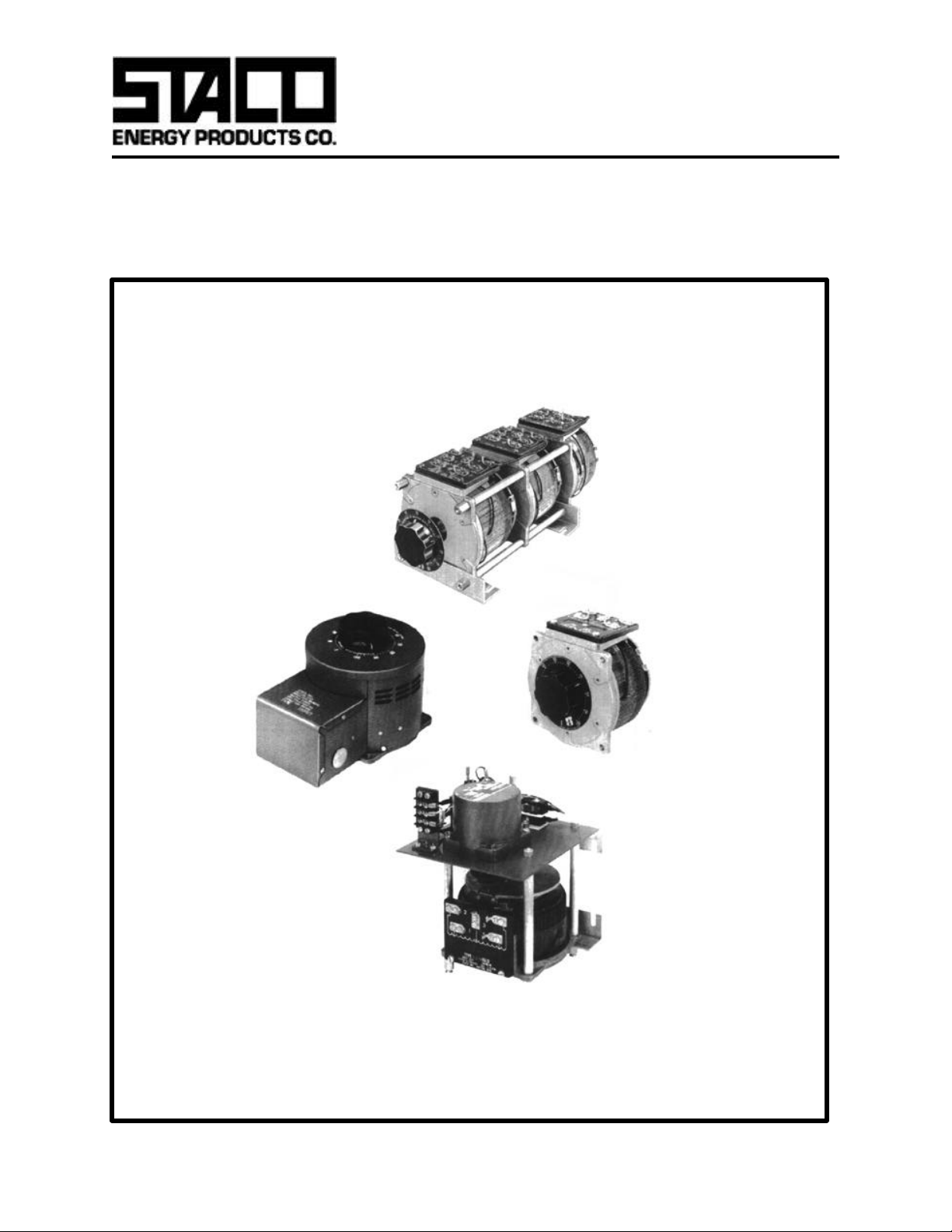
Variable Transformers
ll
Series 1500
9.5 to 15.0 Amperes
1500 Series
The 1510/1520 Series Variable Transformers are highly reliable,
dependable and accurate AC control devices.The 1510, 120 volt
only) or the “CT” style (which also includes a terminal box cover
with knock-outs to accept conduit).
unit is rated at 15 amperes for constant current loads; while the
1520, 240 volt unit is rated at 9.5 amperes for constant current
loads. Constant impedance ratings are listed in the specifications.
They can be operated at frequencies between 50 and 2000 hertz
with derating at higher than rated frequency.
Motor driven units are available in single, two and three ganged
assemblies; cased or uncased styles as identified by the prefix
“M” in the type number. If a motor driven model is ordered, be
sure to prefix the part number with the desired travel time from 0
to maximum of 5, 15, 30, or 60 seconds.
Uncased models have the shaft extending from the base end.
This shaft is fully adjustable and can be extended from either end
for general utility mounting. Cased styles are available in either
“C” style (featuring protective screening over the coil assembly
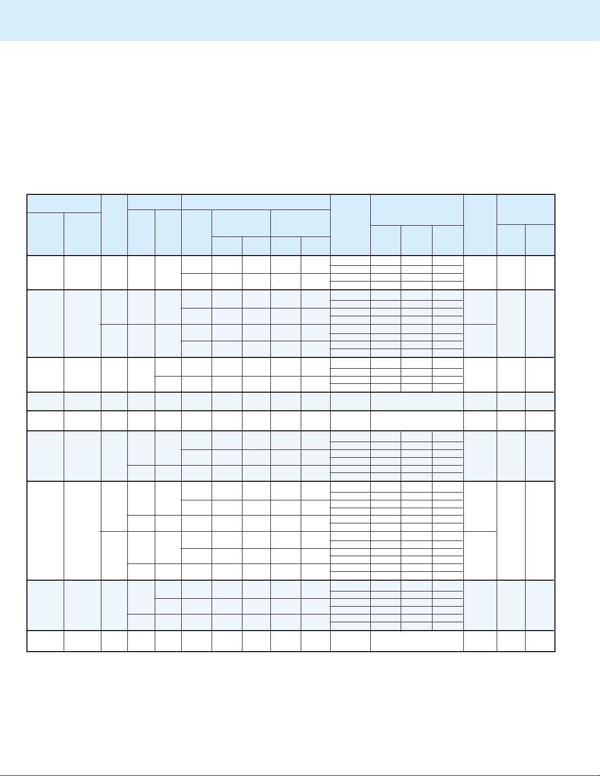
P AR T NUMBER INPUT OUTPUT TERMINAL CONNECTIONS
MANUALLY MOTOR CURRENT IMPEDANCE ROTATION
OPERATED DRIVEN WIRING VOLTS HERTZ VOLTS LOAD LOAD FOR MATIC MAN- MOTOR
1510 M1510+ Single 0-120 15 1.80 20 2.40 CW 2-4 — 4-3
1510C M1510C+ Phase 120 50/60 CCW 2-4 — 2-3
1510CT M1510CT+
Single 0-240 15 3.60 20 4.80 CW 2-2 4-4 3-3
1510-2 M1510-2+ Series 0-280 15 4.20 — — CW 1-1 4-4 3-3
1510C-2 M1510C-2+ CCW 5-5 2-2 3-3
1510CT-2
1510C-3 M1510C-3+ Phase
1510CT-3
3PN1510B —
3PN1510BA
3PN1510BV
1520C-2 M1520C-2+ CCW 6-6 2-2 3-3
1520CT-2
1520C-3 M1520C-3+ Phase
1520CT-3
3PN1520B —
“A” suffix includes Ammeter, “V”suffix includes Voltmeter
+ Motor driven units use terminal connections for CCW increasing voltage, as viewed from the
base end. See Fig 23 on page 9 for motor wiring.
• Jumper provided in the standard common position and should be moved or removed as
required.
++ Line to line voltage
‡ Unit is fused for the constant current rating at the factory.
§ Maximum KV A at maximum output voltage and corresponding derated output current.
Maximum KV A for lower voltages ma y be calculated from derating curve Figure B , page 6.
M1510CT-2+
1510-3 M1510-3+ Three
M1510CT-3+
1520 M1520+
1520C M1520C+
1520CT M1520CT+
1520-2 M1520-2+
M1520CT-2+
1520-3 M1520-3+ Three
M1520CT-3+
Phase 240 50/60 CCW 4-4 2-2 3-3 14 & 4
Three 0-120 15 3.12 20 4.15 CW 2-4-2 4-4 3-4-3
Phase 120++ 50/60 CCW 4-2-4 2-2 3-2-3 14 & 5
Open 0-140 15 3.64 — — CW 1-4-1 4-4 3-4-3
Delta CCW 5-2-5 2-2 3-2-3
240++ CCW 4-4-4 2-2-2 3-3-3
Wye
Single
Phase
Single
—
Phase
Single
Phase CCW 5-2 — 2-3
Single
Phase
Series
Three 240++ 50/60 CCW 4-2-4 2-2 3-2-3
Phase
Open CCW 5-2-5 2-2 3-2-3
Delta
Wye
Single
Phase
120 50/60 CW LINE CORD & RECEPTACLE 3 18 —
120 50/60 CW LINE CORD & RECEPTACLE 9 18 —
240 50/60
120 50/60 0-280 9.5# 1.14§ — —
480 50/60
240 50/60 0-560 9.5# 2.28§ — —
120++
480++
240++
240 50/60 0-280 9.5‡ 2.66 — — CW LINE CORD & RECEPTACLE 3 22 —
0-140 15 2.10 — —
50/60 0-240 15 6.22 20 8.30
60 0-280 15 7.26 — —
0-140 15‡ 2.10 — —
0-140 15‡ 2.10 — —
0-240 9.5 2.28 12 2.88
0-280 9.5 2.66 — —
0-480 9.5 4.56 12 5.76
0-560 9.5 5.32 — —
0-240 9.5 3.95 12 5.0
0-280 9.5 4.61 — —
50/60 0-280 9.5# 1.98§ — —
50/60 0-480 9.5 7.90 12 10
60 0-560 9.5 9.21 — —
60 0-560 9.5# 3.96§ — —
CONST ANT CONST ANT SHAFT
MAX MAX MAX MAX
AMPS KVA AMPS KVA
The synchronous motor is designed for operation on 120 volts,
50/60 hertz single phase lines and draws approximately 0.3
amperes.
(FOR INCREASING VOLTAGE)
AS VIEWED FROM BASE END
VOLTAGE INPUT JUMPER• OUTPUT (Pg 8 & 9) UAL DRIVEN
INCREASE
CW 1-4 — 4-3
CCW 5-2 — 2-3
CW 2-2-2 4-4-4 3-3-3
CW 1-1-1 4-4-4 3-3-3
CCW 5-5-5 2-2-2 3-3-3
CW 2-4 — 4-3
CCW 2-4 — 2-3
CW 1-4 — 4-3
CW 7-4 — 4-3
CCW 6-2 — 2-3
CW 2-2 4-4 3-3
CCW 4-4 2-2 3-3
CW 1-1 4-4 3-3
CCW 5-5 2-2 3-3
CW 7-7 4-4 3-3
CW 2-4-2 4-4 3-4-3
CW 1-4-1 4-4 3-4-3
CW 7-4-7 4-4 3-4-3
CCW 6-2-6 2-2 3-2-3
CW 2-2-2 4-4-4 3-3-3
CCW 4-4-4 2-2-2 3-3-3
CW 1-1-1 4-4-4 3-3-3
CCW 5-5-5 2-2-2 3-3-3
CW 7-7-7 4-4-4 3-3-3
CCW 6-6-6 2-2-2 3-3-3
If ganged units are used in a system that ordinarily has a common neutral or ground
between source and load, the neutral or ground must be connected to the common terminals of the variable transformer assembly. If the system has no neutral, the load must be
balanced or the transformers will be damaged.
# Maximum output current in output voltage range from 0 to 25% above line voltage. At higher
output voltages, the output current must be reduced according to the derating curve,
Figure B, page 6.
SCHE-
14 15 3/4 26
14 & 6 55 1/2 65 3/4
15 19 1/4 29 1/2
15 & 4
15 & 5
15 & 6 66 76 1/4
NET WEIGHT
LBS. MAX.
35 1/4 45 1/2
42 1/4 52 1/2
 Loading...