

Page 1

FIRSTLINE P
Maintenance Bypass
Switch Cabinet
160kVA-250kVA, 480V Input/O utput
With SKRU
USER MANUAL
003-2621
Page 2

Table of Contents
SECTION 1 .......................................................................................................................... 1
Introduction ....................................................................................................................... 1
Overview ........................................................................................................................... 1
Applicability ....................................................................................................................... 2
Part Numbers ................................................................................................................... 2
Section 2 .............................................................................................................................. 3
SAFETY WARNINGS ....................................................................................................... 3
DANGER .......................................................................................................................... 3
WARNING ........................................................................................................................ 3
CAUTION ......................................................................................................................... 4
Section 3 .............................................................................................................................. 5
Cabinet Setup ................................................................................................................... 5
Inspecting the Equipment ................................................................................................. 5
Floor Loading .................................................................................................................... 5
CLEARANCES ................................................................................................................. 5
Unloading the Cabinet(s) .................................................................................................. 6
Attaching the Cabinet to the UPS ..................................................................................... 7
Section 4 .............................................................................................................................. 8
Electrical Installation ......................................................................................................... 8
Wiring Preparation ............................................................................................................ 8
Control Connections ....................................................................................................... 12
Terminal Strip Torque Requirements .............................................................................. 12
Section 5 ............................................................................................................................ 13
Operation ........................................................................................................................ 13
Maintenance Bypass Switch (MBS) ................................................................................ 13
Section 6 ............................................................................................................................ 18
Maintenance ................................................................................................................... 18
Section 7 ............................................................................................................................ 18
FirstLine P Maintenance Bypass Switch Technical Specifications ................................. 18
Table 1 - Symbols ................................................................................................................ 4
Table 2 - Model Floor Loadings ............................................................................................ 5
Table 3 - Wire Size Requirements. .................................................................................... 10
Table 4 - Recommended Crimp Lugs ................................................................................. 10
Table 5 - Maximum Current Ratings................................................................................... 10
Table 6 - Terminal Tightening Torques .............................................................................. 10
Table 7 - Maintenance Bypass Switch States .................................................................... 16
Table 8 - Maintenance Bypass Switch State Change Procedures ..................................... 17
Table 9 - Technical Specifications ...................................................................................... 18
Figure 1 - The FirstLine P Maintenance Bypass Switch Cabinet .......................................... 1
Figure 2 - Pallet Mounting Hardware .................................................................................... 6
Figure 3 - Cabinet to Cabinet Mounting Hole Locations ....................................................... 7
Figure 4 - Inside View of Maintenance Bypass Switch Cabinet ............................................ 9
Figure 5 - Terminal Pa d ........................................................................................................ 9
Figure 7 - Customer Low Voltage Connection Terminal Block ........................................... 12
Figure 8 - Circuit Breaker Sequence Label ........................................................................ 16
Page | ii
Page 3
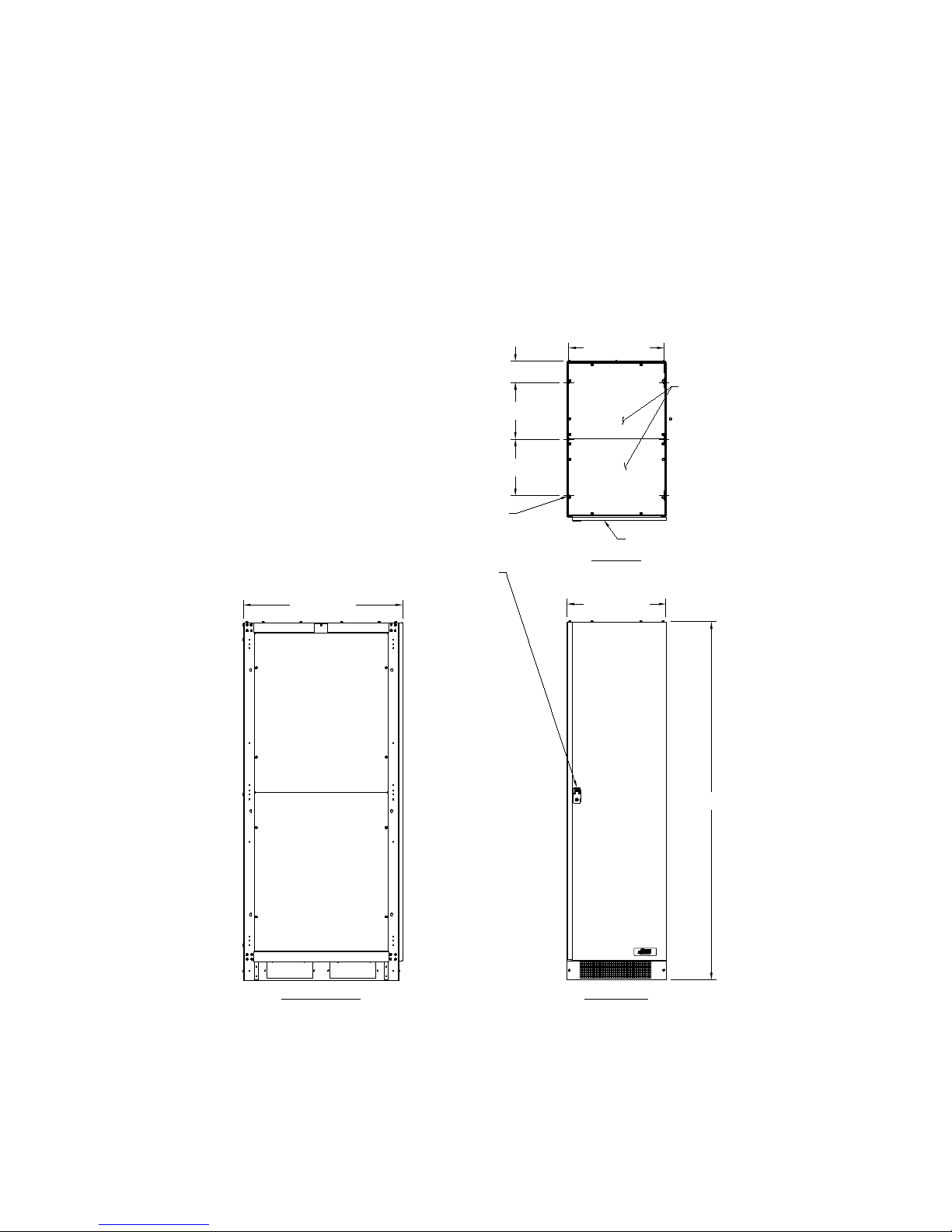
SECTION 1
FRONT VIEW
11.85 [301.0]
11.85 [301.0]
20.00 [507.9]
(6) Ø.41 [Ø10.3]
MOUNTING HOLES
ON BOTTOM FEET
4.46 [113.2]
TOP VIEW
.11 [2.8] THICK
DOOR LATCH REQUIRES PHILLIPS
SCREWDRIVER TO OPEN
75.00 [1905.0]
33.35 [847.0]
20.75 [527.0]
LEFT SIDE VIEW
REMOVABLE TOP
COVERS
.08 [2.0] THICK
HINGED FRONT DOOR
Introduction
Overview
The FirstLine P Mai n te nance Bypass Switch C abi net for 160 kVA, 200 kVA, 250 kVA with
480 V Input and Output is a steel cabinet that attaches to the side of the UPS cabinet,
thereby extending the cabinet, and providing the maintenance bypass function. The
cabinet has conduit attachment points at the top and the botto m for max i mu m flexibility in
wiring the source and load power connections. Please refer to Figure 1 for the outline
drawing of the cabinet.
Figure 1 - The FirstLine P Maintenance Bypass Switch Cabinet
All dimensions in Inches (millimeters)
Page | 1
Page 4

Applicability
This equipment can be applied to UPS models FLU-160-00, FLU-200-00, and FLU-250-00.
These UPS models operate at 480 V, 60 Hz and can be wired as delta in and delta out (3
wire plus ground) or wye in and wye out (4 wire plus ground).
For installations requiring other voltages or other wiring configurations, the equipment
covered by this manual is not appropriate. Please contact Staco Energy Products
Company for recommendations regarding the proper equipment.
It is permissible to use a larger Maintenance Bypass Switch Cabinet (MBS) than is required
for the UPS, but special installation requirements must be met: the power source
connected to the MBS must include circuit protection as specified for the input in the UPS
manual and an output breaker must be provided per the UPS manual. For example, if a
250 kVA MBS is applied to a 160 kVA UPS, a 300 A breaker must be provided at the power
source and a 300 A breaker must be provided between the MBS and the load. If the MBS
rating matches the UPS rating, then the breakers that form the MBS switch arrangement
satisfy the input and output breaker requirement for the UPS.
Part Numbers
FLU-P-160-MBPS*SK for use with 160 kVA UPS
FLU-P-200-MBPS*SK for use with 200 kVA UPS
FLU-P-250-MBPS*SK for use with 250 kVA UPS
Page | 2
Page 5

SECTION 2
SAFETY WARNINGS
IMPORTANT SAFETY INSTRUCTIONS SAVE THESE INSTRUCTIONS
READ AND FOLLOW ALL SAFETY INSTRUCTIONS
• Do not use outdoors.
• Do not route wiring across or near hot surfaces.
• Do not install near gas or electric heaters.
• Equipment should be installed where it will not readily be subjected to tampering by
unauthorized personnel.
• The use of accessory equipment not recommended by the manufacturer may cause
an unsafe condition.
• Do not use this equipment for other than intended use.
• This equipment connects to the output of an uninterruptible power supply.
Hazardous voltages may be present even when the electrical supply to this
equipment is turned off.
• If equipped with a maintenance bypass switch, control connections between this
equipment and the ups must be present to prevent the possibility of backfeed.
• Read and follow the instructions that came with the associated UPS or emergency
lighting system before operating this equipment.
DANGER
This equipment contains lethal voltages. All repairs and service should only be performed
by authorized service personnel. There are no user serviceable parts inside this
equipment. Operation of switches and breakers require access to the cabinet interior and
should only be performed by qualified personnel exercising appropriate caution.
WARNING
This equipment connects to the output of a UPS which contains its own energy source
(batteries). The UPS output may carry live voltage even when the UPS is not connected to
an AC supply.
To reduce the risk of fire and electric shock, install this equipment in a humidity controlled,
indoor environment, free of conductive contaminants. Do not operate near water or
excessive humidity (95% maximum). If condensation is present, the equipment must be
allowed to completely dry before operation.
Page | 3
Page 6
CAUTION
The UPS associated with this equipment contains batteries. Batteries can present a risk of
electrical shock or burn from high short circuit current. Observe proper precautions.
Servicing should only be performed by qualified service personnel knowledgeable of
batteries and the required precautions. Keep unauthorized personnel away from batt eri es .
Read, understand, and follow all instructions in the ups manual before attempting any
operations involving the battery.
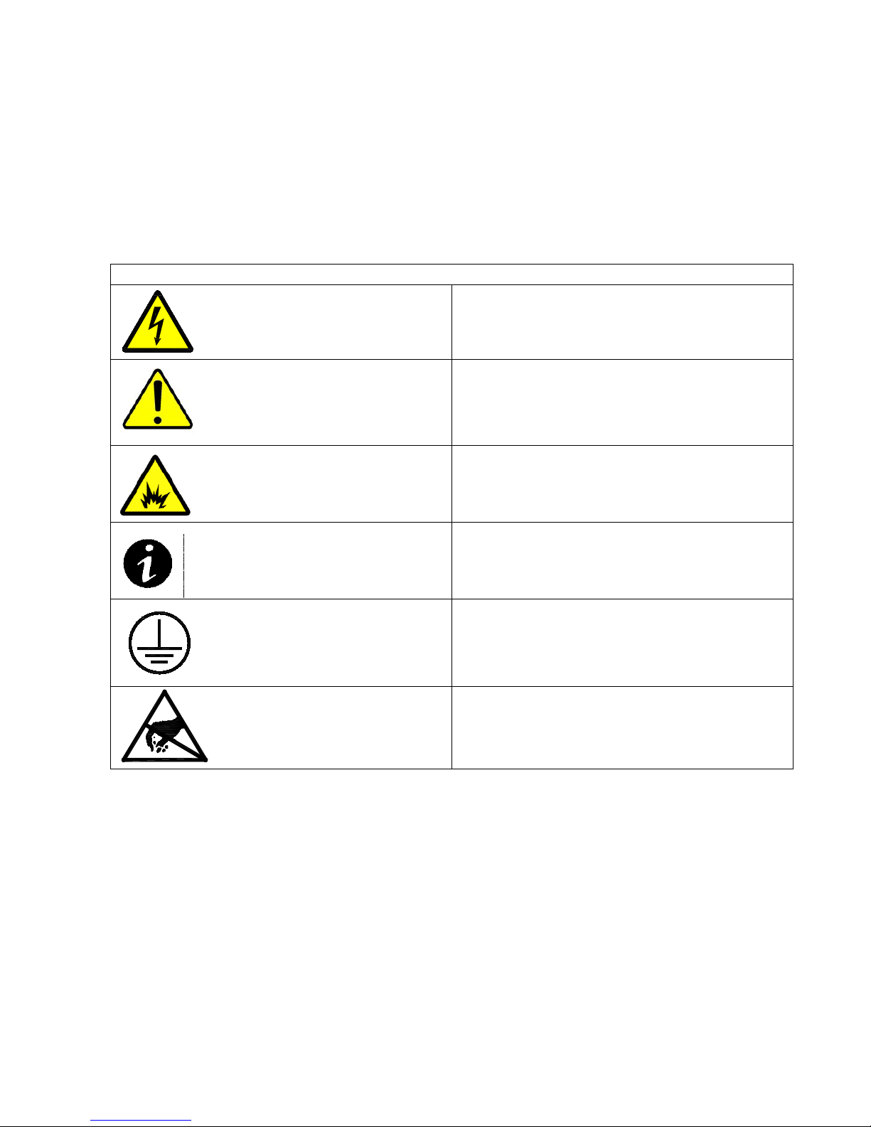
Table 1 - Symbols
Danger / Risk of Electric Shock
Caution
Risk of Explosion
Note
Ground Connection
Electrostatic Sensitive Device
Page | 4
Page 7

STANDARD MODEL FLOOR LOADING
kVA
MAXIMUM WEIGHT
POINT LOADING
160
390 lbs (177 kg)
6.5 lb/in2 (0.5 kg/cm2)
200
390 lbs (177 kg)
6.5 lb/in2 (0.5 kg/cm2)
250
390 lbs (177 kg)
6.5 lb/in2 (0.5 kg/cm2)
From Front of Cabinet
36” (91.4 cm) working space
SECTION 3
Cabinet Setup
This SECTION describes:
Equipment inspection
Floor loading and clearances
Removing and replacing the cabinet panels
Unloading the cabinet(s)
Attaching the cabinet to the UPS
Inspecting the Equipment
If any equipment has been damaged during shipment, keep the shipping and packing
materials for the carrier or place of purchase and file a claim for shipping damage. If you
discover damage after ac ceptance, file a claim for concealed damage.
To file a claim for shipping damage or concealed damage: 1) File with the carrier within 15
days of receipt o f the equipment, 2) Send a copy of the damage claim within 15 days to your
service representative.
Floor Loading
When plan ning the installation, consider the cabinet weight for floor loading. The strength of
the installation surface must be adequate for point and distributed loading. The approximate
weights are shown in the following table.
Table 2 - Model Floor Loadings
CLEARANCES
The following clearances are recommended for the FirstLine P Maintenance Bypass Switch
Cabinet.
Page | 5
Page 8

Unloading the Cabinet(s)
CAUTION
The following tools are required for unloading the cabinet(s):
Wrenches for 3/8” lag bolts.
Forklift or pallet jack
The cabinets are heavy (see Table 2). Unloading the cabinets requires at least two
people to safely remove the cabinets from the pallet.
To remove the Maintenance Bypass Switch cabinet from the ship pallet:
1. Mak e sure the forklift is rated for the cabinet weight.
2. Make sure the path traveled has sufficient support for the combined weight of the
forklift and the cabinet.
3. Make sure forks are at maximum separation.
4. Us e a ver y str ong ratch et str ap (or similar dev ice) of s uffici ent str ength t o tie the uppe r
part of the cabinet to the forklift tower before moving.
5. Keep people out of the fall zone. If the cabinet topples over, stand clear
6. With a Phillip’s screwdriver, remove the two kick panels. These will be rem ounted
when the cabinet is in place.
7. Remove all banding, wrapping and foam protection.
8. Remove the six 3/8” lag bolts securing the cabinet to the pallet. See Figure 2.
9. Lift the cabinet with a forklift one to two inches (1”-2” [2.5-5cm]) above the pallet.
10. Slide the pallet completely away from the raised cabinet.
11. Carefully move the cabinet to the desired location and slowly lower the cabinet to the
floor or other appropriate flat surface.
12. Remount the two kick panels.
Page | 6
Figure 2 - Pallet Mounting Hardware
Page 9

LEFT SIDE VIEW
A
A
A
A
A
A
Attaching the Cabinet to the UPS
The Maintenance Bypass Switch cabinet was constructed so that it can be mounted to the
side of the UPS cabinet if desired. To attach the Maintenance Bypass Switch Cabinet to
the UPS Cabinet:
1. Remove right side panel of UPS and save hardware.
2. Butt left side of MBS cabinet up against the right side of the UPS.
3. Bolt the cabinets together at (6) locations with the supplied 5/16 hardware through
the slots noted as "A" in Figure 3.
4. Mount right side panel of UPS on the right side of the MBS cabinet using the
hardware from the UPS.
Figure 3 - Cabinet to Cabinet Mounting Hole Locations
Page | 7
Page 10

SECTION 4
Electrical Installat i on
Overview
Each of the pieces of equipmen t cov er ed by this manual has four sets of power
connections:
1. Input from the power source, typically, from the electric utility.
2. Power routed to the input of the UPS. If the bypass and rectifier inputs are powered
from separate sources, the bypass input must be fed from the MBS.
3. Power from the output of the UPS.
4. Power to the load
There are four control connections between the Maintenance Bypass Switch Cabinet and
the UPS that must be made. The required control connections are described later in this
section.
A user accessible disconnect device must be provided (by other’s) between the output of
this cabinet and the load. Refer to Table 5 for current requirements.
WARNING
Only qualified service personnel (such as a licensed electrician) should perform
the installation and initial startup. There is a risk of electrical shock.
Wiring Preparation
1. Verify that the equipment is the proper type. The equipment covered by this manual
is 480 V 60 Hz input and output, only. The Maintenance Bypass Switch Cabinet
(MBS) can be used in delta-delta or wy e-wye applications, but the UPS must be
properly configured (refer to the UPS manual). For delta-delta applications where an
input neutral is not provided, the output neutral connection must not be used and the
MBS to UPS neutral connections should be omitted.
2. Plan the locations of conduits. Two Conduit landing plates are provided at the top
(see Figure 1) and bottom of the cabinet. Connections between the MBS and UPS
must be made at the bottom. The landing plates in the rear must be used for the
power connections. As noted above, there are four sets of power connections and
one set of control connections. The low voltage control connection wires must be
routed through the bottom landing plate in the front of the cabinet to ensure physical
separation between th em and the power wiring.
3. All wiring is to be in compliance with all applicable codes.
4. Verify that the source circuit capability is in compliance with the requirements shown
in Table 3 and Table 4.
Page | 8
Page 11

5. Select wire size in compliance with Table 3.
RIGHT SIDE VIEWFRONT VIEW
WITH DOOR AND KICK PANEL REMOVED
NOTE: SHIELD COVER PANELS MUST REMAIN IN
PLACE DURING OPERATION FOR USER SAFETY.
NOTICE
FOR SUPPLY CONNECTIONS,
USE WIRES SUITABLE FOR AT
LEAST 75°C
FOR USE IN A CONTROLLED ENVIRONMENT.
REFER TO HANDBOOK FOR ENVIRONMENTAL
CONDITIONS.
ATTENTION :
Pour utilisation en atmosphère controlée.
Consulter la notice technique pour les
conditions du milieu.
CAUTION!
RISK OF ELECTRIC SHOCK
This Cabinet receives power from more than one
source - disconnection of all ac sources is required
to de-energize this unit before servicing.
NCNOC
CNO NC NCNO
1
1
1
1
1
ATTENTION
ELECTROSTATIC
SENSITIVE DEVICE
UPS OUTPUT BREAKER
MAINTENANCE BYPASS BREAKER
PANELBOARD 1 BREAKER
PANELBOARD 2 BREAKER
DISPLAY ALARM
TEMP ALARM
TO UPS
REQUEST
BYPASS
INPUT
FRONT PANEL
TRIP SWITCH
KEYLOCK
RELEASE
ON BYPASS
TRANSFORMER
TEMP SWITCHES
HTOT
REPO SWITCH
EXTERNAL DC POWER INPUT
DC POWER
OUTPUT
POWER
INPUTS
AC
D24
TB7
TB6TB5 TB4TB3TB2
TB1
TB11TB10
TB8
TB9
J206
J205
J204
J203
J202
J201
F1
DS3
DS1
D45
C1
C2
D20
1 2
3
X1X3X2X4
H2H1
X1X3X2X4
H2H1
WARNING!
TO REDUCE RISK OF FIRE,
REPLACE ONLY WITH SAME TYPE
AND RATING OF FUSE.
UTILITY INPUT
CBA
TO UPS INPUT
CBA
OUTPUT TO LOAD
CBA
FROM UPS OUTPUT
CBA
NEUTRAL
REAR VIEW
WITH REAR COVER REMOVED
UTILITY INPUT
CONNECTIONS
CONNECTIONS
TO UPS INPUT
REMOVABLE CONDUIT LANDING
PLATE FOR POWER WIRING
GROUND
CONNECTIONS
OUTPUT TO LOAD
CONNECTIONS
CONNECTIONS FROM
UPS OUTPUT
GROUND
CONNECTION
NEUTRAL CONNECTIONS
WITH 3/8-16 BOLTS
POWER TERMINAL PADS
WITH 3/8-16 BOLTS
REMOVABLE CONDUIT LANDING
PLATE FOR POWER WIRING
REMOVABLE CONDUIT LANDING
PLATE FOR LOW VOLTAGE
CONNECTIONS
LOW VOLTAGE
CONNECTIONS
CIRCUIT
BREAKER
CIRCUIT
BREAKERS
TOP SHIELD
COVER PANEL
MIDDLE SHIELD
COVER PANEL
BOTTOM SHIELD
COVER PANEL
1.00 [25.4]
1.88 [47.6]
COPPER TERMINAL PAD
3/8-16 BOLTS
6. Recommended crimp terminal lugs are shown in Table 4. The power and neutral
terminal pads, see Figure 4 and Figure 5, are provided with 3/8-16 bolts.
Figure 4 - Inside View of Maintenance Bypass Switch Cabinet
Figure 5 - Terminal Pad
Page | 9
Page 12

Table 3 - Wire Size Requirements.
Minimum
Wire Size
Required
Breaker
160
500 kcmil or (2) 2/0
AWG
300 kcmil
3 AWG
300 A
200
500 kcmil or (2) 2/0
AWG
2 AWG
350 A
250
(2) 300 kcmil
(2) 4/0 AWG
1 AWG
450 A
Bolt Size
Wire
Thomas & Betts Two
Hole Connectors
Thomas & Betts Single
Hole Connectors
2/0
54210
54110
3/0
54211
54111
4/0
54212
54112
250 kcmil
54213
54174
300 kcmil
54214
54179
350 kcmil
54215
256-30695-112
400 kcmil
54216
54116
500 kcmil
54218
256-30695-339
kVA Rating
Rated Input
Rated Output Current
160
212
192
200
265
241
250
331
301
Bolt Size
Torque
3/8 - 16
260 inch - pounds
Wire Size
Torque
#6 AWG – 300 kcmil
275 inch - pounds
Wire Size
Torque
# 26-10 AWG
5.3 – 7.0 inch - pounds
*Wire must be rated 75°C or higher. Use copper conductors only.
kVA
Rating
Table 4 - Recommended Crimp Lugs
3/8
Minimum Input Wire
Size
(2) 3/0 AWG
Minimum Output Wire
Size
Ground
Supply
Table 5 - Maximum Current Ratings
Current (Amps)
Table 6 - Terminal Tightening Torques
INPUT / OUTPUT/NEUTRAL TERMINAL TORQUE
GROUND LUG TORGUE
LOW VOLTAGE TERMINALTORQUE
(Amps)
Page | 10
Page 13

Wiring Installation
1. Switch off utility power to the distribution point where the UPS will be connected. Be
absolutely sure that there are no hazardous voltages present. Use lockout/tagout
procedures to assure safety.
2. Remove as many panels as needed for adequate access for wiring the cabinet. Open
the front door of the MBS Cabinet. I f nec es s ar y, remove the top and bottom shield
cover panels located above and below the circuit breakers by removing the four (4)
screws that mount each in place. See Figure 4.
3. Connect wires from the "TO UPS INPUT" bus bar terminal pads, see Figure 4 and
Figure 5, to the input terminals in the UPS. (Refer to the UPS manual). The wire must
be in compliance with Table 3 and the terminals must be torqued in compliance with
Table 6. Make sure that phase A connects to phase A and so on. If the bypass and
rectifier inputs are powered from separate sources, the bypass input must be fed from
the MBS.
4. Connect wires from the "FROM UPS OUTPUT" bus bar termi n al pads to the output
terminals in the UPS. (Refer to the UPS manual). The wire must be in compliance with
Table 3 and the terminals must be torqued in compliance with Table 6. Make sure that
phase A connects to phase A and so on.
5. Connect wir es from the "OUTPUT TO LOAD" bus bar terminal pads to the loa d. Th e
load may be an external distribution panel, etc. If neutral is not needed by the load,
then it does not need to be supplied. The wire must be in compliance with Table 3 and
the terminals must be torqued in compliance with Table 6. Make sure that phase A
connects to phase A and so on.
6. A set of four or five control connections must be installed from the "CUSTOMER LOW
VOLTAGE CONNECTION TERMINAL BLOCK " to the Remote Commands and Alarm
Connections in the front of the UPS cabinet. These control wires must be physically
separated from any power wires. The length of the control wires is limited to 30 feet or
10 meters. These connections are described later in this section.
7. Verify that the input power source is not powered. Connect wires from the "UTILITY
INPUT" bus bar term inal pads to the input source power from the building distribution.
The wire must be in compliance with Table 3 and the terminals must be torqued in
compliance with Table 6. Make sure that phase A connects to phase A and so on.
The source needs to have A-B-C phase sequence. If not, exchange two of the phase
connections to correct thi s.
8. If the system is the used in a wye-wye application, ensure that the neutral wires are
connected to the “Neutral” bus bar terminal pad.
9. Check all work. Replace the panels that were removed for access. Insure that the
shield cover panels have been mounted in place. Failure to do so could subject
personnel to lethal voltages.
Page | 11
Page 14

Control Connections
Four control connections must be made between the Maintenance Bypass Switch Cabinet
(MBS) and the UPS in order to provide backfeed protection, a required safety feature
The wiring to these low voltage (“ELV”) connections must be kept separated from the
higher voltage wiring. Refer to Figure 4 regarding the Low Voltage Terminal Block and to
the UPS manual that shows the connection point in the UPS.
Connections between the Maintenance Bypass Switch Cabinet and the UPS
Since these wires affect the operation of the UPS, they should be protected. Running them
in conduit is a good idea, even if local codes do not require conduit. It is also
recommended that the wires are shielded twisted pairs. Alpha 6010C is a shielded cable
with three twisted pairs and is available from a number of sources in various spool lengths.
Two pairs are required:
Pair 1 - First wire from terminal 2 of the Low Voltage Connecti o n Ter mi nal Bloc k (LV TB) o f
the Maintenance Bypass Switch Cabinet to terminal 11 of the Remote Commands and
Alarms Connections on the UPS (RCA-UPS). Second wire from terminal 1 of LVTB to
terminal 12 of RCA-UPS.
Pair 2 – First wire from terminal 3 of LVTB to terminal 1 of RCA-UPS. Second wire from
terminal 4 of LVTB to terminal 2 of RCA-UPS.
Figure 7 is an electrical wiring schematic summarizing the connections to the Low Voltage
Connection Terminal B l ock .
Terminal Strip Torque Requirements
The terminals on the Customer Low Voltage Connection Terminal Block must be torqued to
5.3 to 7.0 inch-lbs. The terminals on the Control Connections (on the UPS) must be torqued
to 4.4 inch-lbs.
Figure 6 - Customer Low Voltage Connection Terminal Block
Page | 12
Page 15

SECTION 5
Operation
Refer to the User's Manual for the UPS for instructions on operating the UPS part of the
system. If the UPS is part of a parallel system, special operating instructions apply.
Maintenance Bypass Switch (MBS)
The purpose of the Maintenance Bypass Switch (MBS) is to facilitate servicing the UPS
without removing power from the load. The main functional components of the MBS are
three circuit breaker s that are used as disconnect switches. We will designate them
“BKR1”, “BKR2”, and “BKR3”, but they are labeled “1”, “2”, and “3” above the breaker
handles on the front inner cover of the cabinet. The breakers each have three positions: off
(down), on (up), and tripped (in between off and on). To turn on a tripped breaker, reset
the breaker by pushing the handle down to the off position, then raise it to the on position.
If a breaker will not reset or trips as being turned on, the backfeed prevention interlock is
active and the proper conditions (as described below) will have to be present before the
breaker can be operated. When closed, BKR1 supplies power from the supply (utility) to
the bypass input of the UPS. For single input UPS configurations, it also supplies power to
the rectifier input. When closed, BKR3 connects the output of the UPS to the load. When
closed, BKR2 bypasse s the pat h through BKR1, the UPS, and BKR3 and connects the
supply directly to the load. BKR2 and BKR3 must never be closed at the same time unless
the UPS is in bypass mode. It does not matter which type of bypass, but bypass via
SWMB is the simplest to engage. There are signals that support an interlock function to
prevent BKR2 from being closed unless BKR3 is open or the UPS is in bypass mode. For
the UPS to be able to issue this signal, the UPS controls must be powered. Always
observe proper switching sequence to avoid loss of power to the load Common switching
operations are also described, below. There are also some problem scenarios listed.
The three switches (Breaker 1, Breaker 2, and Breaker 3) have eight possible combinations
or "States". Table 7 lists all of the possible states. Note that one possibility (Breaker 1
open, Breaker 2 and Breaker 3 closed) is forbidden as unexpected system behavior could
result, including loss of power to the load. The Overlap State is a transient state. It is the
"make" before the "break". Time spent in this state should be kept to a minimum as
external events could lead to tripping Breaker 2, possibly interrupting power to the load.
Also, please note that the UPS does not condition the power to the load while in bypass
and that battery back-up is not available while in bypass.
To avoid damage to the UPS and to avoid interrupting power to the load, the procedures
listed in Table 8 must be used to change from one state to another. The MBS is equipped
with a label (see Figure 8) that describes the breaker sequenc es for two common
operations. The "To place load on maintenance bypass" sequence describes going from
Normal State to Overlap to UPS Unloaded to Maintenance. The "To place load on UPS"
sequence describes going from Maintenance State to UPS Unloaded to Overlap to Normal.
Page | 13
Page 16

Common MBS operations: (refer to the UPS manual for UPS operations; BKR1,
BKR2, BKR3 are part of the Maintenance Bypass Switch Cabinet; all other switches
are part of the UPS)
To transfer from normal mode on the UPS to maintenance bypass—
1. Verify that the bypass source is satisfactory: at minimum, verify that the bypass
source lamp (LED1 at upper left) on the front panel of the UPS is steady green and
that the legend “BYPASS VOLTAGE FAIL” is not present on the display. If the load
is already being supported by the Static Bypass, the yellow “Load on Bypass” lamp
(LED4, upper right) will be steady (or flashing if the load exceeds the UPS rating).
Refer to Section 6 of the UPS manual regarding the indicators.
2. Close SWMB on the UPS. After SWMB is closed, the yellow “Load on Bypass” lamp
will flash and the inverter will stop and battery supported operation is no longer
possible.
3. Close BKR2.
4. Open BKR3.
5. Shut down the UPS, if desired, by opening SWOUT, SWIN, SWBY, and open the
Battery Disconnect(s). Optionally open SWMB.
6. If the UPS is shut down, open BKR1. The UPS is completely de-energized at this
point.
To transfer from MBS to normal mode—
1. Close BKR1.
2. On the UPS, verify that SWMB is closed, if not, close it.
3. Close SWBY, SWIN, and SWOUT. Wait 5 seconds.
4. Close BKR3.
5. Open BKR2.
6. Open SWMB. The UPS should start and operate normally.
7. When the display no longer shows: “Wait: DO NOT connect the BATTERY”, the
disconnect breakers in each battery cabinet should be closed. Refer to Section 4.6
for the proper procedure for connecting the battery.
Normal start-up with load unpowered—
1. Verify that BKR2 is open; open it if closed.
2. Verify that SWBY is open.
3. Close BKR1 and BKR3.
4. Perform a normal UPS start-up as per Section 4.6 of the UPS manual.
Page | 14
Page 17

Need to get power to the load, but the condition of the UPS is uncertain—
1. Verify that the load is truly not powered.
2. Verify that the utility source is suitable (applying power to the load using the MBS is
at the operator’s risk).
3. Verify that BKR1 and BKR3 are open; open them if necessary.
4. Close BKR2. The load is now powered via the MBS. The UPS is not functional and
battery supported operation is not possible.
Need to operate the UPS as part of maintenance, but wish to maintain power to
load—
1. If UPS is running, perform transfer from normal mode to MBS, as instructed, above.
After opening BKR3, the UPS can be left powered (via BKR1) and/or its mode can
be changed as desired.
2. If BKR2 is already closed, close BKR1 to apply power to the UPS. If the UPS is dual
input, there is another supply that must be applied to power the rectifier.
3. There is some risk in starting the UPS while the load is powered via BKR2 (MBS
mode). A fault in the UPS could cause the upstream circuit protection (circuit
breaker or fuse) to operate, removing power from both the faulted UPS input and the
MBS input and, therefore, the output.
Potential Problems:
MBS will not allow BKR2 to close—
1. Check to see that the UPS is on bypass (SWMB is closed).
2. The UPS controls must be powered (BKR1 and SWBY should be closed).
3. Verify that the backfeed prevention interlock signals were properly wired as part of
the installation and that this wiring has not been damaged.
BKR2 in the MBS trips when power is applied—
1. This is likely due to a procedural error. Note that BKR2 and BKR3 must not be
closed at the same time unless the UPS is powered and the UPS is in bypass mode.
2. It is likely that BKR3 is closed and the backfeed prevention interlock function is
preventing BKR2 from stay i ng clos ed.
3. Since the UPS is not powered, the signal that indicates that the UPS is in bypass
mode cannot be generated.
4. Open BKR3 and close BKR2. BKR2 should close and stay closed.
5. If power to the UPS is not required, open BKR1.
Page | 15
Page 18

Figure 7 - Circuit Breaker Sequence Labe l
Breaker 1 = Left hand breaker = UPS Input
Breaker 2 = Center breaker = Bypass
Breaker 3 = Right hand breaker = UPS Output
State Name
Breaker
1
Breaker
2
Breaker
3
Adjacent State(s)
Normal
closed
open
closed
Test Battery
Overlap
closed
closed
closed
Normal, UPS
Unloaded
UPS Unloaded
closed
closed
open
Overlap, Maintenance
Maintenance
open
closed
open
UPS Unloaded, Load
Off
Load Off
open
open
open
Maintenance, Test
UPS
Test UPS
closed
open
open
Load Off, Normal
Test Battery
open
open
closed
Normal
Not Allowed
open
closed
closed
(none)
Table 7 - Maintenance Bypass Switch States
Overlap, Test UPS,
Page | 16
Page 19

Table 8 - Maintenance Bypass Switch State Change Procedures
(refer to Table 9 for description of states)
From State
To State
Procedure
Normal
Overlap
1. Select Manual Bypass Mode on UPS.
2. Verify load on bypass by observing front panel of UPS.
3. Close Breaker 2.
Overlap
Normal
1. Open Breaker 2.
2. Select Automatic Transfer to Inverter Mode on UPS.
Overlap
UPS
Unloaded
Open Breaker 3.
UPS
Unloaded
Overlap
1. Select Manual Bypass Mode on UPS.
2. Verify load on bypass by observing front panel of UPS.
3. Close Breaker 3.
UPS
Unloaded
Maintenance
1. Turn Off UPS
2. Open Breaker 1.
Maintenance
UPS
Unloaded
1. Close Breaker 1.
2. Turn On UPS
Maintenance
Load Off
Open Breaker 2. (This removes power from load!)
Load Off
Maintenance
Close Breaker 2.
Load Off
Test UPS
1. Close Breaker 1.
2. Turn On UPS, if desired.
Test UPS
Load Off
1. Turn Off UPS.
2. Open Breaker 1.
Test UPS
Normal
1. Turn Off UPS.
2. Close Breaker 3.
3. Turn On UPS.
Normal
Test UPS
Open Breaker 3. (This removes power from load!)
Normal
Test Battery
Open Breaker 1. Battery will discharge while Breaker 1 is open.
Test Battery
Normal
Close Breaker 1.
Page | 17
Page 20

Environmental
Altitude
De-rate load capability above 1000 meters 1% per 100
meters.
Operating Temperature
40o C Maximum
Humidity
Maximum 95%RH, Non-condensing
Electrical
160 kVA
200 kVA
250 kVA
Rated voltage
480/277
480/277
480/277
Rated Current
212A
265A
331A
Breaker Rating
300A
350A
450A
Minimum Wire Size INPUT
500 kcmil or
(2) 2/0 AWG
OUTPUT
500 kcmil or
(2) 2/0 AWG
Heat Rejection – L ess than (BTU/Hr)
800
1000
1250
SECTION 6
Maintenance
There are no wear items in the MBS that require periodic replacement. However, regular
care will assure maximum availability of power.
Keep the ventilation openings in the cabinet free of dust and debris.
Wipe the cabinet exterior with a soft cloth, slightly dampened with water, to remove dust.
Consider performing periodic infrared temperature measurements on the circuit breaker
terminations. This will require access to the cabinet interior. There are hazardous voltages
present and any work must be performed using caution. Only trained service personnel
should perform this work. Elevated temperatures of the terminations usually are the sign of
a loose connection, but can also signal that a breaker is failing. Loose connections should
only be serviced after removal of power.
If the system is powered down, consider removing accumulated dust from the cabinet
interior using a vacuum cleaner.
SECTION 7
FirstLine P Maintenance Bypass Switch Technical Specifications
Table 9 - Technical Specifications
(2) 3/0 AWG (2) 300 kcmil
300 kcmil
(2) 4/0 AWG
Page | 18
 Loading...