

Page 1

FIRSTLINE PLT
Battery Cabinet
FLP-BAT-080-150-2-B-30K
USER MANUAL
003-2620
Page 2

CONTENTS
Section 1 ......................................................................................................................... 1
Section 2 ......................................................................................................................... 2
Safety Warnings .......................................................................................................... 2
Battery Life .................................................................................................................. 5
Section 3 ......................................................................................................................... 6
Battery Cabinet Setup .................................................................................................. 6
Inspecting the Equipment ............................................................................................ 6
Floor Loading ............................................................................................................... 6
Clearances .................................................................................................................. 6
Unloading the Cabinet(s) ............................................................................................. 7
Section 4 ......................................................................................................................... 8
Electrical Installation .................................................................................................... 8
Wiring Preparation ....................................................................................................... 8
Connecting to the Firstline PL Battery Cabinet .......................................................... 11
Section 5 ....................................................................................................................... 14
Circuit Breaker Interface ............................................................................................ 14
Section 6 ....................................................................................................................... 15
Battery Removal, Installation, and Service ................................................................ 15
Maintenance .............................................................................................................. 17
Table 1 - Symbols ........................................................................................................... 3
Table 2 - Model Floor Loadings ....................................................................................... 6
Table 3 - Terminal Tightening Torques and Wires Sizes ............................................... 13
Table 4 - Replacement Batteries and Operating Temperatures .................................... 17
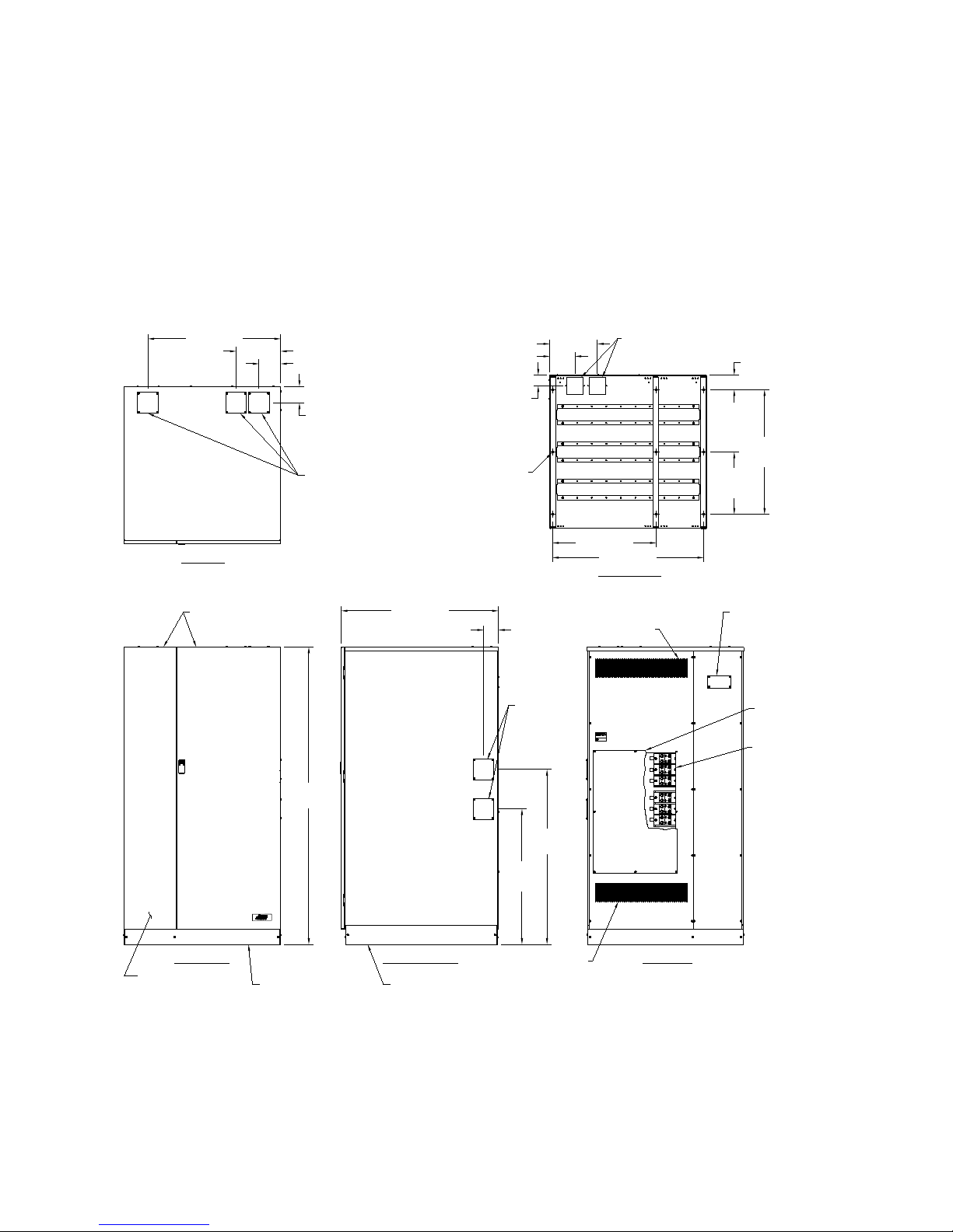
Figure 1 - The FirstLine PL Battery Cabinet .................................................................... 1
Figure 2 - Pallet Mounting Hardware ............................................................................... 7
Figure 3 - Battery Cabinet with Front Doors Removed .................................................... 9
Figure 4 - Front Internal View ........................................................................................ 10
Figure 5 - Power Connections ....................................................................................... 11
Figure 6 – Circuit Breaker Interface Connections .......................................................... 14
Figure 7 - Battery Bus Bar ............................................................................................. 15
Figure 8 - Battery Tray .................................................................................................. 16
Figure 9 - Cabinet Schematic ........................................................................................ 19
Page | ii
Page 3
REMOVABLE COVERS
FRONT AND REAR
REMOVABLE SIDE COVERS
FRONT VIEW
TOP VIEW
RIGHT SIDE VIEW
REAR VIEW
BOTTOM VIEW
AS VIEWED
FROM BOTTOM
U
L
UPS
BATTERY SUPPLY
2DA6
3.56 [90.5]
37.86 [961.6]
32.62
[828.7]
42.12
[1070.0]
71.58
[1818.2]
5.20 [132.2]
10.70 [271.9]
31.95 [811.6]
WIRE ACCESS
COVERS
TOP WIRE ACCESS COVERS
4.00 [101.6] SQUARE
OPENINGS TYPICAL
BOTTOM WIRE ACCESS COVERS TOWARD REAR
4.00 [101.6] SQUARE OPENINGS
(9) Ø.44 [Ø11.1]
MOUNTING HOLES
6.11 [155.2]
11.48 [291.7]
2.58 [65.4]
3.51 [89.2]
15.00
[381.0]
30.00
[762.0]
36.41 [924.7]
N
+
_
N
+
_
POWER TERMINAL
BLOCKS
AIR VENT
AIR VENT
3.94 [100.0]
FUSES AND CIRCUIT
BREAKERS BEHIND
LEFT DOOR
25.00 [635.0]
POWER TERMINAL
ACCESS COVER
BATTERY BREAKER
INTERFACE TERMINAL
BLOCK ACCESS COVER
HINGED FRONT DOORS
SECTION 1
The FirstLine PL Extended Run Time Battery Cabinet for 30kVA are used in conjunction
with the FirstLine PL/PLT 30 KVA uninterruptible power supplies (UPS) to prevent loss
of valuable electronic information and minimize equipment downtime. During brownouts,
blackouts, and other power interruptions, batteries provide emergency power to
safeguard operation .
Figure 1 shows the FirstLine PL Battery Cabinet.
Figure 1 - The FirstLine PL Battery Cabinet
Page | 1
Page 4

IMPORTANT SAFETY INSTRUCTIONS
This manual covers battery cabinets with the following part numbers:
FLP-BAT-030-150-2-B-30K: battery cabinet fused at 90A (suitable for 30 KVA), 2
battery string matched to 208V UPS (204 cell system),
with breakers.
FLP-BAT-030-150-2-N-30K: battery cabinet fused at 90A (suitable f or 30 KVA), 2
battery string matched to 208V UPS (204 cell system),
without breakers.
SECTION 2
SAFETY WARNINGS
This manual contains important instructions that you should follow during installation
and maintenance of the battery cabinet. Please read all instructions before operating
the equipment and save this manual for fut ur e re ferenc e.
READ AND FOLLOW ALL SAFETY INSTRUCTIONS
a. Do not use outdoors.
b. Do not route wiring across or near hot surfaces.
c. Do not install near gas or electric heaters.
d. Use caution when servicing batteries. Battery acid can cause burns to skin
and eyes. If acid is spilled on skin or in eyes, flush acid with fresh water and
contact a physician immediately.
e. Equipment should be installed where it will not readily be subjected to
tampering by unauthorized personnel.
f. The use of accessory equipment not recommended by the manufacturer may
cause an unsafe condition.
g. Do not use this equipment for other than intended use.
SAVE THESE INSTRUCTIONS
Page | 2
Page 5
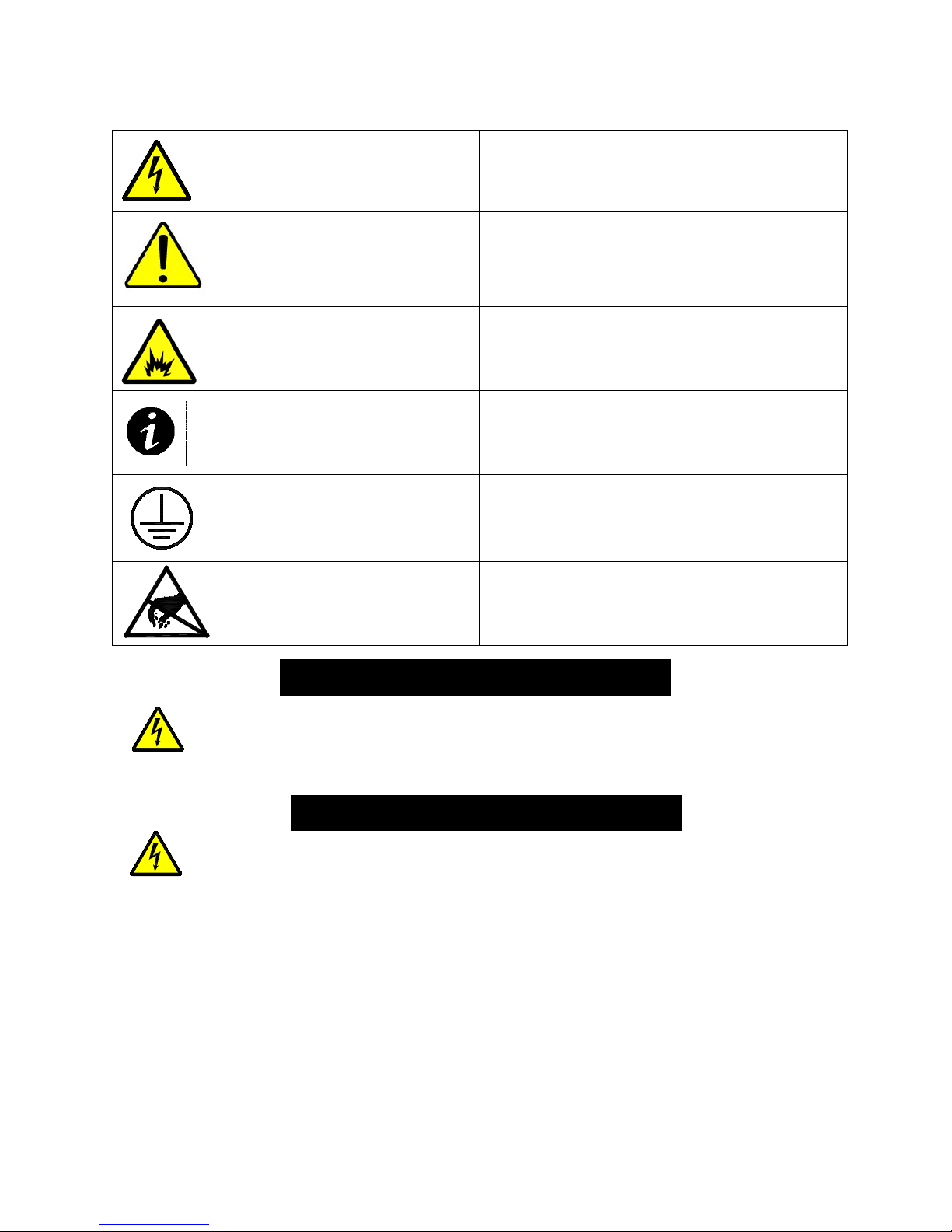
DANGER
WARNING
Table 1 - Symbols
Danger / Risk of Electric Shock
Caution
Risk of Explosion
Note
Ground Connection
Electrostatic Sensitive Device
This battery cabinet co ntai ns LE THAL VOLTAGES. All repairs and service
should be performed by AUTHORIZED SERVICE PERSONNEL ONLY. There
are NO USER SERVICEABLE PARTS inside the battery cabinet.
This battery cabinet contains its own energy source (batteries). Hazardous
voltage may be present even when the battery cabinet is not connected to a
power source.
To reduce the risk of fire or electric shock, install this battery cabinet in a
temperature and humidity controlled, indoor environment, free of conductive
contaminants. Do not operate near water or excessive humidity (95%
maximum).
Page | 3
Page 6

CAUTION
Batteries can present a risk of electrical shock or burn from high short circuit
current. Observe proper precautions. Servicing should be performed by
qualified service personnel knowledgeable of batteries and required
precautions. Keep unauthorized personnel away from batteries.
Risk of explosion if batteries are replaced by an incorrect type. Replace with
same type and rating only.
Proper disposal of batteries is required. Refer to your local codes for disposal
requirements.
Never dispose of batteries in a fire. Batteries may explode when exposed to
flame.
This product contains Value Regulated Sealed Acid Batteries. These batteries
contain lead, a neurotoxin, and sulfuric acid, a corrosive. Additionally, the
energy stored in the batteries can present a shock hazard and a burn hazard.
Batteries should only be serviced by trained personnel. Appropriate safety
precautions must be observed, including eye protection and skin protection.
Contact with electrolyte requires flushing with a generous amount of clean
water. Seek medical attention immediately following contact with electrolyte.
Unwanted batteries must be recycled and should never be discarded.
CAUTION: A battery can present a risk of electrical shock and short circuit
current. The following precautions should be observed when working on
batteries:
1. Remove watches, rings, or other metal objects.
2. Use tools with insulated handles.
3. Wear rubber gloves and boots.
4. Do not lay tools or metal parts on top of the batteri es .
5. Disconnect charging source prior to connecting or disconnecting battery
terminals.
6. Determine if the battery is inadvertently grounded. If inadvertently
grounded, remove source of ground. Contact with any part of a grounded
battery can result in electric shock. The likelihood of such shock will be
reduced if such grounds are removed during installation and maintenance
(applicable to a UPS and a remote battery supply not having a grounded
supply circuit).
Page | 4
Page 7
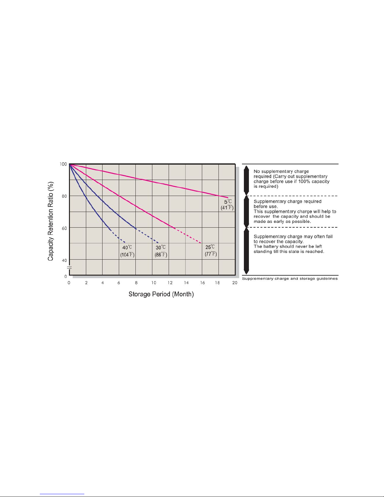
BATTERY LIFE
The batteries in your Staco UPS system were shipped from the factory fully charged. If
you plan to place the batteries in storage for any period of time prior to installation and
startup then the following precaution should be followed.
Batteries placed in storage will age. How fast they will age depends on the storage
temperature. The batteries are rated for storage over a temperature range of -15o C to
40o C (5o F to 104o F). The amount of time the batteries may be stored without recharge
varies greatly with storage temperature. Please consult the following table. If the
batteries are allowed to sit in storage for an excessive period of time before recharging
then they are subject to irreversible damage.
Once the batteries are placed into service and fully charged, the useful life of the
batteries will be reduced if they are subjected to high temperatures. The operating
temperature range of -15
short periods of time. Batteries operating continuously at or near 40
a shorter useful life than batteries operating continuously at 25
o
C to 40o C (5o F to 104o F) must not be exceeded for even
o
o
C. Battery life will be
C will experience
further shortened if the batteries are allowed to fully discharge and then left in that
condition for extended per i ods of time. As soon as the load is removed from the battery
it will continue to age at a higher rate than a fully charged battery. The longer the
battery remains discharged the greater the risk of irreversible damage.
Allowing the batteries to become damaged due to; a) operation or storage outside
the rated temperature range, b) storage for extended periods of time without
recharge per the table above, or c) sitting for a period of time in a discharged
state will void the battery warranty.
Page | 5
Page 8

Model
Maximum Weight
Point Loading
FLP-BAT-080-150-2-B-30K
3148 Lbs (1428 kg)
27.4 lb/in2 (1.9 kg/cm2)
FLP-BAT-080-150-2-N-30K
3132 Lbs (1421 kg)
27.3 lb/in2 (1.9 kg/cm2)
From Front of Cabinet
36” (91.4 cm) working space
From Back of Cabinet
6” (15.2 cm)
From Side of Cabinet to UPS
Minimum 24” (61 cm)
SECTION 3
BATTERY CABINET SETUP
This SECTION describes:
Equipment inspection
Floor loading and clearances
Removing and replacing the cabinet panels
Unloading the cabinet(s)
INSPECTING THE EQUIPMENT
If any equipment has been damaged during shipment, keep the shipping and packing
materials for the carrier or place of purchase and file a claim for shipping damage. If you
discover damage after acceptance, file a claim for concealed damage.
To file a claim for shipping damage or concealed damage: 1) File with the carrier within
15 days of receipt of the equipment, 2) Send a copy of the damage claim within 15 days
to your service representative.
FLOOR LOADING
When planning the installation, consider the battery cabinet weight for floor loading. The
strength of the installation surface must be adequate for point and distributed loading.
The approximate weights are shown in the following table.
Table 2 - Model Floor Loadings
STANDARD MODEL FLOOR LOADING
CLEARANCES
The following clearances are recommended for the FirstLine PL Extended Run Time
Battery Cabinet.
Page | 6
Page 9

CAUTION
UNLOADING THE CABINET(S)
The following tools are required for unloading the cabinet(s):
Wrenches for 3/8” lag bolts.
Forklift or pallet jack
Phillips screwdriver
The Battery cabinets are heavy (see Table 2). Unloading the cabinets requires at
least two people to safely remove the cabinets from the pallet.
To remove the battery cabinet from the ship pallet:
1. Make sure the forklift is rated for the cabinet weight.
2. Make sure the path traveled has sufficient support for the combined weight of the
forklift and the battery cabinet.
3. Make sure forks are at maximum separation.
4. Use a very strong ratchet strap (or similar device) of sufficient strength to tie the
upper part of the cabinet to the forklift tower before moving.
5. Keep people out of the fall zone. If the cabinet topples over, stand clear.
6. Remove all banding, wrapping and foam protection.
7. Remove the six 3/8” lag bolts securing the cabinet to the pallet. (See Figure 2)
8. Lift the cabinet with a forklift one to two inches (1”-2” [2.5-5cm ]) above the pallet.
9. Slide the pallet completely away from the raised cabinet.
Page | 7
Figure 2 - Pallet Mounting Hardware
Page 10

WARNING
10. Carefully move the cabinet to the desired location and slowly lower the cabinet to
the floor or other appropr iat e fla t sur f ace. Bolt to the floor if desired.
11. With a Phillips screwdriver mount the four kick panels that were wrapped and
placed in the cabinet.
SECTION 4
ELECTRICAL INSTALLATION
The FirstLine PL Extended Run Time Battery Cabinet has the following power
connections:
TB1, 3 pole (positive, neutral, negative) terminal block and ground connection for
battery power input. This goes to the UPS or to the next battery cabinet closer to
the UPS.
TB2, 3 pole (positive, neutral, negative) terminal block and ground connection for
battery power output. This goes to the input of the next battery cabinet in the set.
TB3, 3 pole (positive, neutral, negative) terminal block and ground connection for
battery power output. This goes to the input of the –N version battery cabinet
from the first –B version battery cabinet closest to the UPS.
TB3 is energized at all times. Opening the circuit breakers does not
remove power from this terminal block.
Only qualified service personnel (such as a licensed electrician) should
perform the UPS installation and initial startup. Risk of electrical shock.
WIRING PREPARATION
To begin wiring the UPS:
1. Verify that the electrical connections to the installation site have been properly
installed.
2. A wall-mounted, user-supplied, readily-accessible disconnection device must be
incorporated in the battery input wiring unless at least one of the battery
cabinets is a –B version.
3. Wire the FirstLine PL/PLT UPS per the User’s Handbook.
Page | 8
Page 11

CIRCUIT BREAKERS
For Equipment Service
And Support
1-866-261-1191
Staco Energy Products Co.
301 Gaddis Boulevard
Dayton, OH 45403
Phone: 1-937-253-1191
Fax: 1-937-253-1723
www.stacoenergy.com
Service is to be performed only
Do NOT open.
by authorized personnel.
No user serviceable parts inside.
ATTENTION :
Pour utilisation en atmosphère controlée.
Consulter la notice technique pour les
conditions du milieu.
FOR USE IN A CONTROLLED ENVIRONMENT.
REFER TO HANDBOOK FOR ENVIRONMENTAL
CONDITIONS.
BATTERY
CIRCUIT BREAKER
BATTERY
CIRCUIT BREAKER
DO NOT DISCONNECT
UNDER LOAD
BATTERIES BEHIND
THIS PANEL
FUSES BEHIND
THIS PANEL
Do not close the circuit breakers until
the display of the UPS shows:
Close Battery Switch
Closing the breakers before this may damage
the UPS or blow fuses in the battery cabinet.
WARNING!
4. Switch off utility power to the distribution point where the UPS is connected. Be
absolutely sure there is no power.
5. Open the front doors.
Figure 3 - Battery Cabinet with Front Doors Removed
6. If the optional circuit breakers are included, switch them to the “OFF” position.
7. Remove the inner right front cover by removing the (10) ten screws mounting it to
the enclosure.
8. Remove the terminal access cover on the rear of the cabinet by removing the (8)
eight screws mounting it to the enclosure (see Figure 5).
Page | 9
Page 12

CIRCUIT BREAKERS
BATTERY TRAYS
U1
R3
R2
R1
Q1
J3
J2
J1
F1
D2
D1
DANGER
RISK OF ELECTRIC SHOCK
Do not touch uninsulated
battery terminals.
CAUTION!
WARNING!
TO REDUCE RISK OF FIRE,
REPLACE ONLY WITH SAME TYPE
AND RATING OF FUSE.
DANGER
RISK OF ELECTRIC SHOCK
Do not touch uninsulated
battery terminals.
CAUTION!
DANGER
RISK OF ELECTRIC SHOCK
Do not touch uninsulated
battery terminals.
CAUTION!
DANGER
RISK OF ELECTRIC SHOCK
Do not touch uninsulated
battery terminals.
CAUTION!
DANGER
RISK OF ELECTRIC SHOCK
Do not touch uninsulated
battery terminals.
CAUTION!
DANGER
RISK OF ELECTRIC SHOCK
Do not touch uninsulated
battery terminals.
CAUTION!
BATTERY FUSES
9. Conduit landing plates are located toward the rear of the cabinet on the top cover,
side panels, and base to accommodate bottom wire entry to the cabinet (see
Figure 1). Remove plates and drill or punch hole to fit conduit bushing with
Greenlee punch or similar device. Make certain that the bushing will be clear
in the opening in the base. Mount bushing to plate and tighten to
manufacturer’s recommendations. Replace the plates and mount conduit.
Figure 4 - Front Internal View
Page | 10
Page 13

REAR VIEW
POWER TERMINAL
ACCESS COVER
TERMINAL BLOCKS
COMPRESSION LUGS
(2) CONNECTIONS PER POLE
500 KCMIL - #4 AWG WIRE EACH
GROUND STUD
BATTERY BREAKER
INTERFACE BLOCK
ACCESS COVER
R
U
L
UPS
BATTERY SUPPLY
2DA6
N
+
_
N
+
_
N
+
_
WARNING!
TB3 is energized at all times. Opening
the circuit breakers does not remove
power from this terminal block.
CONNECTING TO THE FIRSTLINE PL BATTERY C ABINET
To be performed by authorized service personnel:
1. Inspect battery trays for signs of damage. Verify that all terminal connections are
sound. The red and black “powerpole” connectors will be connected, but the
blue and white connectors on the wires joining the trays in the string should not
be connected.
2. If possible, after connecting the loose “powerpole” connections (blue to blue,
white to white), use a voltmeter to verify that the battery string is above 408 VDC
at the TB3 connector. If the voltage is low or the voltage varies significantly from
string to string, please consult Staco service.
Figure 5 - Power Connections
Page | 11
Page 14

3. The battery cabinet(s) to be installed must include the at least one –B version.
The fi rst –B cabinet must have its input terminal block (TB1) wired directly to the
UPS. To wire additional battery cabinets, wire from TB2 of the first battery
cabinet to TB1 of the second –B battery cabinet. Repeat these steps for
additional –B cabinets. Use wire sized per local codes, #6 AWG 75°C copper
wire minimum to #3/0 A WG max i mum.
When a –N version cabinet is installed with a –B cabinet, the –B cabinet must
have its TB1 terminal block wired to the UPS or another –B cabinet. To wire
from the –B cabinet to the –N cabinet, wire from TB3 of the –B cabinet to TB1 of
the –N cabinet. To wire additional –N battery cabinets, wire from TB2 of the first
–N battery cabinet to TB1 of the second –N battery cabinet. Repeat these steps
for additional -N cabinets.
There must be at least one –B cabinet among the battery cabinets. If it is desired
to create a battery system involving all –N version cabinets and a user provided
disconnect switch, contact Staco for requirements for the disconnect switch.
Please note that a custom configuration of this type is not covered by Staco’s UL
Listing, nor is it covered by this manual.
TB3 is energized at all times. Opening the circuit breakers does not
remove power from this terminal block.
4. Connect the ground wire to the ¼-20 ground stud with a ring terminal or pressure
lug by removing and replacing the top nut and washers only with a 7/16” wrench.
5. Before working within the UPS cabinet, verify that the UPS has no pow er applied.
Before touching the Extended Run Time Battery connector in the UPS, verify that
all internal battery strings are disconnected (that is, verify that the blue and white
“powerpole” connectors are NOT mated). Refer to the UPS manual. Repeat
procedures 3 and 4 to the FirstLine PL UPS Extended Run Time Batter y
connector located in the lower left side of the UPS. We recommend that the wires
be marked as to which is positive (+) and negative (-) to ensure that the wires are
not accidentally crossed. See Figure 9.
Never connect the positive to the negative. Severe damage and injury
could result. Check polarity at the TB3 terminal block.
6. For –B cabinets, connect the Circuit Breaker Interface per Sec ti on 5 .
7. Mate the blue connections, blue to blue, and then the white connections, white to
white. See Figure 9. Repeat this procedure for the other battery cabinets, if
present.
8. Rei ns tal l th e fro nt inner panel on each battery cabinet using the screws provided.
Page | 12
Page 15

WIRE SIZE
TORQUE
#2/0 - #6 AWG
120 inch-pounds
WIRE SIZE
TORQUE
#10 – 26 AWG
5.3 – 7.0 inch-pounds
Extended Run Time Battery Cabinet
100 inch-pounds
UPS Cabinet
55 inch-pounds
Minimum Input/Output
Wire Size
Minimum Ground Wire
Size
30
#2 AWG
#8 AWG
9. After the internal batteries in the UPS are connected, reinstall any panels that
were removed and close the UPS doors. Refer to the UPS manual for guidance
regarding this procedure. Do not close the Battery Cabinet circuit breakers until
the display of the UPS shows the message: “Close Battery Switch”. Closing the
breakers before this may damage the UPS or blow fuses in the Battery Cabinet.
Once the Battery cabinet circuit breakers are closed the front doors of the battery
cabinet may be closed.
Terminal blocks on the –N version cabinets are disconnected by unplugging the
“powerpole” connectors in all cabinets. This requires the removal of the inner
panel by authorized personnel only.
Table 3 - Terminal Tightening Torques and Wires Sizes
BATTERY INPUT/OUTPUT TERMIN AL
TIGHTENING TORQUE
TB4 LOW VOLTAGE TERMINAL TORQUE
GROUND STUD TIGHTENING TORQUE
kVA Rating
*Wire must be rated 75°C or higher. Use copper conductors only.
Page | 13
Page 16

SECTION 5
CIRCUIT BREAKER INTERFACE
NOTE: Disregard this section if tripping the battery cabinet breakers via REPO
activation is not required.
Figure 5 shows the location of the Battery Breaker Interface terminal block on the
battery cabinet.
NOTE: Wires to the Battery Breaker Interface terminal block TB4 must not enter
the UPS or battery cabinet through the same port as the input/output or battery
power wires.
Figure 6 – Circuit Breaker Interface Connections
To trip the battery circuit breakers via the REPO of the UPS, connect the battery cabinet
interface connector (TB4) to the UPS per Figure 6. If any additional battery cabinets
are –N versions, no other connections are needed.
CAUTION: The Battery Breaker Interface Board is an electrostatic sensitive
device. The user should be grounded when connecting to this assembly.
CAUTION: If the battery cabinet circuit breakers trip or are opened, the internal
batteries of the UPS are still connected and providing power to the UPS. They
also cause the terminals of the TB1 and TB2 to be energized with hazardous
voltage.
Page | 14
Page 17

+
+
-
+
-
+
-
+
-
+
-
+
-
+
-
+
-
-
+
-
+
-
-
+
REMOVE THESE BUS BARS
BEFORE SERVICING THE
BATTERY TRAYS
SECTION 6
BATTERY REMOVAL, INSTALLATION, AND SERVICE
The batteries must only be serviced by authorized service personnel. Always wear eye
protection and have eye wash near at hand. Never work on any connections that have
not been disconnected from all other sources of voltage. Parallel connected battery
cabinets require that all battery strings in all battery cabinets be disconnected before
working within any particular cabinet. Also, the UPS is usually equipped with internal
batteries that must be disconnected before service (refer to the UPS manual).
Before servicing batteries, the UPS should be turned off, power should be removed
from the UPS input, and all battery breakers and disconnect switches should be open.
If a Maintenance Bypass Switch (MBS) is present, power to the load can be maintained
during service. Refer to the instructions for the MBS to put the system in bypass mode
before removing power from the UPS.
Before any battery service is attempted, the batteries must be disconnected by
unplugging the cables to the battery trays. If it is necessary to remove the cables from
the batteries, the connections should be marked in a way that no confusion will exist
when it is time to reconnect the cables (see Figure 9). The batteries are mounted in
slide out trays that permit access to the battery to battery connections when the trays
are withdrawn from the cabinet.
To service the battery trays, they must be removed from the cabinet by
a fork lift. The 2 bus bars at the back of the tray, as shown in Figure 7,
must be removed before servicing or replacing the batteries.
Page | 15
Figure 7 - Battery Bus Bar
Page 18

Battery tray
Battery shelf
Notch
Extension limit tab
Cutaway side view of battery tray
batteries not shown for clarity
Tray mounting screw
WARNING
Never connect the two cables from a battery tray or from a battery string (two trays)
together as severe damage will occur, resulting in fire and/or injury. Battery connections
If batteries are being replaced, only use the same manufacturer and battery type and
rating as the battery removed. When the bus bars connecting the batteries are
removed, be careful to avoid dropping bolts or shifting the bus bars so that they might
short across adjacent battery terminals. We recommend using a piece of electrical
insulating paper (for example, “Nomex”) as a temporary shield between the bus bars
during service.
It is very important that only one tray at a time be extended from the cabinet. If more
than one tray is extended, the cabinet can become unstable and topple over.
After each tray is installed or serviced, it must be fully inserted and secured using the
supplied threaded fasteners before attempting to install or service another tray.
If the trays are to be removed, always remove the highest tray first. The battery tr ays
are very heavy and it will be necessary to use a lifting device to support the trays as
they are removed. When the trays are to be reinstalled, use the procedure in the
following paragraph.
The battery trays are very heavy and it will be necessary to use a lifting device to
support the trays as they are installed. Do not take away the external support until the
extension limit tabs on the upper sides of the battery tray are inserted past the notches
on the upper edge of the battery shelf (see Figure 8). Always install the lowest battery
tray first. After it is inserted fully into the support shelf, secure the tray with the supplied
threaded fasteners. After all of the trays are reinstalled and secured, reconnect the
cables using the markings as a guide.
should only be made by a person wearing eye protection. It is advised that eye wash be
available. If there are any doubts about the proper connections, do not proceed.
Figure 8 - Battery Tray
Page | 16
Page 19

RECOMMENDED REPLACEMENT INTERVALS
Batteries
2 to 5 years1
OPERATING TEMPERATURE
Recommended Range
15-25º C (59-77º F)
Maximum Range
10-40º C (50-104º F)
Quantity
Required
-080-150
China Storage Battery
HRL12150W
36 Per String
MAINTENANCE
The FirstLine PL Extended Run Time Battery Cabinet is designed to be virtually user
maintenance free, requiring only the occasional wipe with a damp cloth or non-abrasive
cleaner.
Spare kits are available for the FirstLine PL Extended Run Time Battery Cabinet series,
please contact Staco Energy Products Co. service center for details.
For maximum availability of the UPS, the batteries should be replaced as part of a
comprehensive pr ev ent ive maintenance program.
Table 4 - Replacement Batteries and Operating Temperatures
REPLACEMENT BATTERY
Cabinet Model Manufacturer Cat. Number
This product contains Value Regulated Sealed Acid Batteries.
These batteries contain lead, a neurotoxin, and sulfuric acid, a corrosive. Additionally,
the energy stored in the batteries can present a shock hazard and a burn hazard.
Batteries should only be services by trained personnel. Appropriate safety precautions
must be observed, including eye protection and skin protection. Contact with electrolyte
requires flushing with generous amounts of clean water. Seek medical attention
immediately following contact with electrolyte. Unwanted batteries must be recycled
and should never be discarded.
The functional lifetime of batteries is significantly affected by the temperature at which
they are stored and operated. Ideally, batteries should be used in a 70° F (21° C)
environment. For every 15° F (8.3° C) increase in temperature, the life expectancy of a
battery will be halved.
1
Battery life is highly dependent on the ambient temperature and the number and depth of discharge
cycles. A discharged battery should be recharged as soon as possible. If the battery is left in a discharged
state, irreversible sulfation occurs, reducing the capacity (run-time) of the battery.
Page | 17
Page 20

Exposure to temperatures in excess of 90°F (32°C) should be limited to no more than
30 days per year. Under no circumstances should the battery be exposed to
temperatures over 104° F (40° C) which can lead to thermal runaway, a condition that
damages the battery. Thermal runaway can cause batteries to swell. If the battery
cases burst, the hazardous contents may be exposed.
Maintaining proper ambient temperature usually requires installing the product in a
temperature controlled space. Equipment rooms without cooling systems do not
generally maintain the proper conditions for good battery life.
Page | 18
Page 21

TRAY 3
TRAY 2
TRAY 1
WHITE
F1
RED CONNECTORS
BLUE
BLACK CONNECTORS
RED CONNECTORS
+
N
CUSTOMER WIRING
TO UPS
CIRCUIT
BREAKER
INTERFACE
BOARD
CB1
CB2
1
2
1
2
J1
-
+
N
-
+
N
-
TB3
BATTERY
CONNECTOR
1+
2-
3+
TB4
CONTROL
CONNECTOR
4-
TB2
BATTERY
CONNECTOR
TB1
BATTERY
CONNECTOR
U1
R3
R2
R1
Q1
J3
J2
J1
F1
D2
D1
TRAY 6
CB1
CB2
TRAY 5
TRAY 4
TRAY 3
TRAY 2
TRAY 1
F1
F2
F3
F4
CONNECTORS
CONNECTORS
TRAY 6
TRAY 5
TRAY 4
WHITE
BLUE
CONNECTORS
CONNECTORS
RED CONNECTORS
BLACK CONNECTORS
F22
F3
F4
BLACK CONNECTORS
CONTROL TERMINAL BLOCK
LOCATED ON REAR PANEL
TB4
FRONT VIEW
DOORS AND COVERS REMOVED
CIRCUIT BREAKER
INTERFACE BOARD
CIRCUIT BREAKERS
*
* WARNING:
TB3 IS ENERGIZED AT ALL TIMES. OPENING
THE CIRCUIT BREAKERS DOES NOT REMOVE
POWER FROM THIS TERMINAL BLOCK.
CIRCUIT BREAKERS AND
CIRCUIT BREAKER INTERFACE
BOARD NOT PROVIDED ON
-N BATTERY CABINETS
FUSES
Page | 19
Figure 9 - Cabinet Schematic
 Loading...