

Page 1

003-2593
FirstLine Parallel Output
Redundant Cabinet
FLP-10-POPC-5-R-4Y-2Y
10kVA
USER MANUAL
Page | i
Page 2

Staco Energy is highly specialized in the development and production of uninterruptible
power systems (UPS). The UPS’s of this series are high quality products, carefully
designed and manufactured to ensure optimum performance.
No reproduction of any part of this manual, even partial, is permitt ed without the
authorization of Staco Energy Products Company. The Staco Energy Products Company
reserves the right to modify the product described herein, in order to improve it, at any time
and without notice.
301 Gaddis Boulevard • Dayton, Ohio 45403
U.S. Toll Free 866-261-1191
(937) 253-1191 • Fax: (937) 253-1723
Web site: www.stacoenergy.com
Thank you for choosing our product.
Page | ii
Page 3

Table of Contents
SECTION 1 .......................................................................................................................... 1
Introduction ....................................................................................................................... 1
Overview ........................................................................................................................... 1
Section 2 .............................................................................................................................. 2
SAFETY WARNINGS ....................................................................................................... 2
DANGER .......................................................................................................................... 2
WARNING ........................................................................................................................ 2
CAUTION ......................................................................................................................... 3
Section 3 .............................................................................................................................. 4
Cabinet Setup ................................................................................................................... 4
Inspecting the Equipment ................................................................................................. 4
Floor Loading .................................................................................................................... 4
CLEARANCES ................................................................................................................. 4
Unloading the Cabinet(s) .................................................................................................. 5
Section 4 .............................................................................................................................. 6
Electrical Installation ......................................................................................................... 6
Wiring Preparation ............................................................................................................ 6
Control Connections ....................................................................................................... 10
Connections Between the Parallel Output Redundant Cabinet and the UPS ................. 10
Terminal Strip Torque Requirements .............................................................................. 10
Switch Settings ............................................................................................................... 10
SECTION 5 ........................................................................................................................ 12
Backfeed Protection ........................................................................................................ 12
Remote EPO (Emergency Power Off) ............................................................................ 13
Section 6 ............................................................................................................................ 14
REPO ............................................................................................................................. 16
Section 7 ............................................................................................................................ 17
Maintenance ................................................................................................................... 17
Section 8 ............................................................................................................................ 17
Parallel Output Redundant Cabinet Technical Specifications ......................................... 17
Table 1 - Symbols ................................................................................................................ 3
Table 2 - Model Floor Loadings ............................................................................................ 4
Table 3 - Wire Size Requirements ....................................................................................... 8
Table 4 - Maximum Current Ratings..................................................................................... 8
Table 5 - Terminal Tightening Torques ................................................................................ 8
Table 6 - Technical Specifications ...................................................................................... 17
Figure 1 - The Firstline Parallel Output Redundant Cabinet ................................................ 1
Figure 2 - Pallet Mounting Hardware .................................................................................... 5
Figure 3 - Inside Front View of Parallel Output Redundant Cabinet ..................................... 7
Figure 4 - Options Control Board Assembly ....................................................................... 11
Figure 5 - Customer Low Voltage Connection Terminal Block ........................................... 11
Figure 6 - Circuit Breaker Sequence Label ........................................................................ 16
Page | iii
Page 4
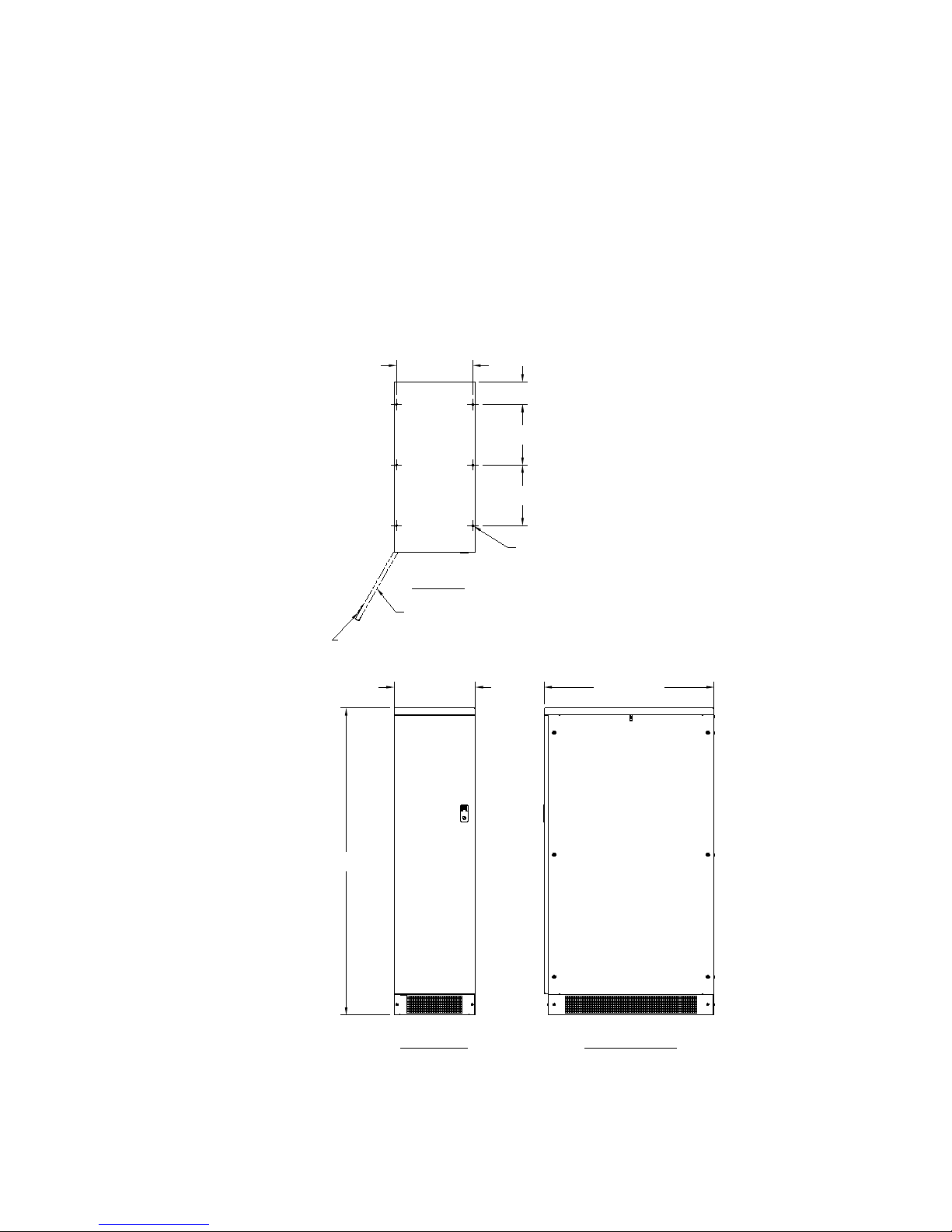
33.35 [847.0]
15.99 [406.1]
60.16 [1528.0]
15.00 [380.9]
4.46 [113.2]
11.85 [301.0]
11.85 [301.0]
(6) Ø.41 [Ø10.3]
MOUNTING HOLES
ON BOTTOM FEET
.11 [2.8] THICK
TOP VIEW
HINGED FRONT DOOR
DOOR LATCH REQUIRES PHILLIPS
SCREWDRIVER TO OPEN
FRONT VIEW RIGHT SIDE VIEW
SECTION 1
Introduction
Overview
The Firstline Parallel Output Redundant Cabinet is a steel cabinet that matches the UPS
cabinet, and provides the maintenance bypass function. The cabinet has conduit
attachment points at the top and the bottom for maximum flexibility in wiring the source and
load power connections.
Please refer to Figure 1 for the outline drawing of the cabinet.
Figure 1 - The Firstline Parallel Output Redundant Cabinet
Page | 1
Page 5

SECTION 2
SAFETY WARNINGS
IMPORTANT SAFETY INSTRUCTIONS SAVE THESE INSTRUCTIONS
READ AND FOLLOW ALL SAFETY INSTRUCTIONS
• Do not use outdoors.
• Do not route wiring across or near hot surfaces.
• Do not install near gas or electric heaters.
• Equipment should be installed where it will not readily be subjected to tampering by
unauthorized personnel.
• The use of accessory equipment not recommended by the manufacturer may cause
an unsafe condition.
• Do not use this equipment for other than intended use.
• This equipment connec ts to the output of an uninterruptible pow er supply.
Hazardous voltages may be present even when the electrical supply to this
equipment is turned off.
• If equipped with a maintenance bypass switch, control connections between this
equipment and the UPS must be present to prevent the possibility of backfeed.
• Read and follow the instructions that came with the associated UPS or emergency
lighting system before operating this equipment.
DANGER
This equipment contains lethal voltages. All repairs and service should only be performed
by authorized service personnel. There are no user serviceable parts inside this
equipment. Operation of switches and breakers require access to the cabinet interior and
should only be performed by qualified personnel exercising appropriate caution.
WARNING
This equipment connects to the output of a UPS which contains its own energy source
(batteries). The UPS output may carry live voltage even when the UPS is not connected to
an AC supply.
To reduce the risk of fire and electric shock, install this equipment in a humidity controlled,
indoor environment, free of conductive contaminants. Do not operate near water or
excessive humidity (95% maximum). If condensation is present, the equipment must be
allowed to completely dry before operation.
Page | 2
Page 6
CAUTION
The UPS associated with this equipment contains batteries. Batteries can present a risk of
electrical shock or burn from high short circuit current. Observe proper precautions.
Servicing should only be performed by qualified service personnel knowledgeable of
batteries and the required precautions. Keep unauthorized personnel away from batteries.
Read, understand and follow all instructions in the UPS manual before attempting any
operations involving the battery.
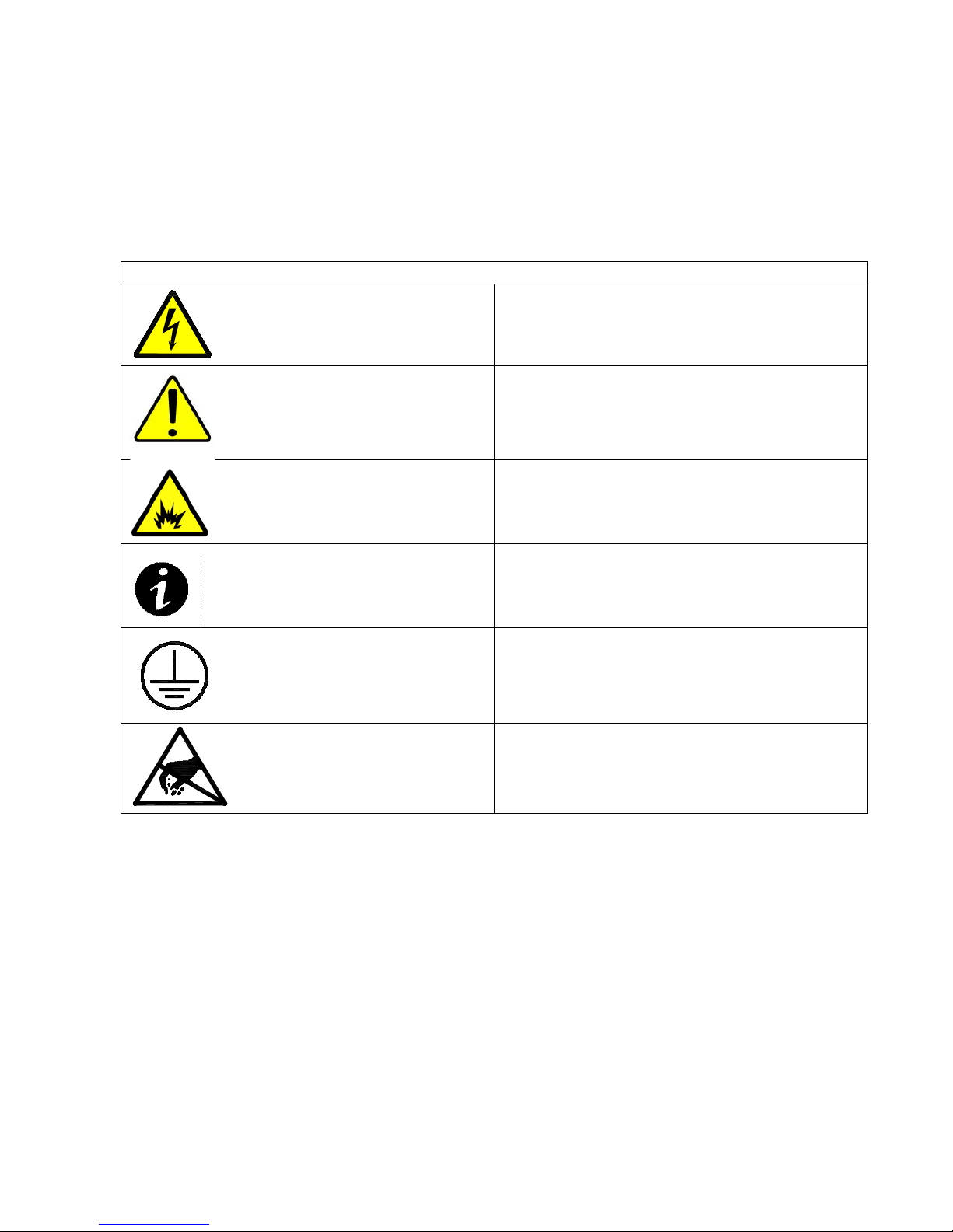
Table 1 - Symbols
Danger / Risk of Electric Shock
Caution
Risk of Explosion
Note
Ground Connection
Electrostatic Sensitive Device
Page | 3
Page 7

STANDARD MODEL FLOOR LOADING
MAXIMUM WEIGHT
POINT LOADING
460 lbs (209 kg)
7.8 lb/in2 (0.48 kg/cm2)
From Front of Cabinet
36” (91.4 cm) working space
SECTION 3
Cabinet Setup
This SECTION describes:
Equipment inspection
Floor loading and clearances
Removing and replacing the cabinet panels
Unloading the cabinet(s)
Attaching the cabinet to the UPS
Inspecting the Equipment
If any equipment has been damaged during shipment, keep the shipping and packing
materials for the carrier or place of purchase and file a claim for shipping damage. If you
discover damage after acceptance, file a claim for concealed damage.
To file a claim for shipping damage or concealed damage: 1) File with the carrier within 15
days of receipt o f the equipment, 2) Send a copy of the damage claim within 15 days to your
service representative.
Floor Loading
When planning the installation, consider the battery cabinet weight for floor loading. The
strength of the installation surface must be adequate for point and distributed loading. The
approximate weights are shown in the following table.
Table 2 - Model Floor Loadings
CLEARANCES
The following clearances are recommended for the Maintenance Bypass Switch Cabinet.
Page | 4
Page 8

Unloading the Cabinet(s)
CAUTION
The following tools are required for unloading the cabinet(s):
Wrenches for 3/8” lag bolts.
Forklift or pallet jack
The cabinets are heavy (see Table 2). Unloading the cabinets requires at least two
people to safely remove the cabinets from the pallet.
To remove the Parallel Output Redundant Cabinet from the ship pallet:
1. Make sure the forklift is rated for the cabinet weight.
2. Make sure the path traveled has sufficient support for the combined weight of the
forklift and the cabinet.
3. Mak e sure for k s are at maximum separation.
4. Us e a ver y str ong ratch et str ap (or similar dev ice) of s uffici ent str ength t o tie the u pper
part of the cabinet to the forklift tower before moving.
5. Keep people out of the fall zone. If the cabinet topples over, stand clear
6. With a Phillip’s screwdriver, remove the two kick panels. These will be remounted
when the cabinet is in place.
7. Remove all banding, wrapping and foam protection.
8. Remove the six 3/8” lag bolts securing the cabinet to the pallet. See Figure 2.
9. Lift the cabinet with a forklift one to two inches (1”-2” [2.5-5cm]) above the pallet.
10. Slide the pallet completely away from the raised cabinet.
11. Carefully move the cabinet to the desired location and slowly lower the cabinet to the
floor or other appropriate flat surface.
12. Remount the two kick panels.
Page | 5
Figure 2 - Pallet Mounting Hardware
Page 9

SECTION 4
Electrical Installat i on
Overview
Each of the pieces of equipmen t cov er ed by this manual has six sets of power connections:
1. Input from the power source, typically, from the electric utility.
2. Power routed to the input of the first UPS.
3. Power routed to the input of the second UPS.
4. Power from the output of the first UPS.
5. Power from the output of the second UPS.
6. Power to the load
There are eight control connections between the Parallel Output Redundant Cabinet and
the two UPS cabinets that must be made. The required control connections are described
later in this section.
A user accessible disconnect device must be provided (by others) between the output of
this cabinet and the load. Refer to Table 4 for current requirements.
WARNING
Only qualified service personnel (such as a licensed electrician) should
perform the installation and initial startup. There is a risk of electrical shock.
Wiring Preparation
1. Verify that the equipment is the proper type. The equipment covered by this manual
is 480V 60 Hz input and 208V output, only. The Parallel Output Redundant Cabinet
can only be used in a wye-wye application. An input neutr al con ne c ti on is required.
2. Plan the locations of conduits. Two Conduit landing plates are provided at the
bottom of the cabinet. Power connections between the Parallel Output Redundant
and the UPS must be made through the bottom landing plate in the rear of the
cabinet to the bus bar terminal pads provided behind the circuit breakers on each
side of the cabinet above the lower row of breakers. The conduits must be placed
toward the rear o f the c abi ne t a minimum of 6-1/4 inches away from the low voltage
wiring terminal lock, see Figure 3.
3. Power connections from the utility input and output load must be made through the
top of the cabinet to the bus bar terminal pads located behind the top row of
breakers and in the middle of the lower row of breakers.
Page | 6
Page 10

4. The low voltage control connection wires must be routed from the terminal block
through the bottom lan ding plate in the front of the cabinet to ensur e physical
separation between th em and the power wiring.
5. All wiring is to be in compliance with all applicable codes.
6. Verify that the source circuit capability is in compliance with the requirements shown
in Table 3 and Table 4.
7. Select wire size in compliance with Table 3.
Figure 3 - Inside Front View of Parallel Output Redundant Cabinet
Page | 7
Page 11

Table 3 - Wire Size Requirements
Minimum Input
Minimum
Size
Minimum
Size
Required
#12 AWG
#8 AWG
#10 AWG
25 A
Rated Input
Rated Output Current
18
28
Bolt Size
Torque
¼ - 20
75 inch - pounds
Wire Size
Torque
#10 - #14 AWG
35 inch - pounds
#8 AWG
40 inch - pounds
#4 - #6 AWG
45 inch - pounds
1/0 - #2 AWG
50 inch - pounds
Wire Size
Torque
# 26-10 AWG
5.3 – 7.0 inch - pounds
*Wire must be rated 75°C or higher
Wire Size
Output Wire
Table 4 - Maximum Current Ratings
Current (Amps)
Table 5 - Terminal Tightening Torques
INPUT / OUTPUT / NEUTRAL TERMINAL TORQUE
GROUND LUG TORGUE
Ground Wire
(Amps)
Supply Breaker
LOW VOLTAGE TERMINALTORQUE
Page | 8
Page 12

Wiring Installation
1. Switch off utility power to the distribution point where the UPS will be connected. Be
absolutely sure that there are no hazardous voltages present. Use lockout/tagout
procedures to assure safety.
2. Remove as many panels as needed for adequate access for wiring the cabinet. Open
the front door of the MBS Cabinet.
3. Connect wires from each of the "TO UPS INPUT" terminal pads to the input terminals
of each UPS. (Refer to the UPS manual). The wire must be in compliance with Table
3 and the terminals must be torqued in compliance with Table 5. Make sure that
phase A connects to phase A and so on.
4. Connect wires from each of the "FROM UPS OUTPUT" terminal pads to the output
terminals of each UPS. (Refer to the UPS manual). The wire must be in compliance
with Table 3 and the terminals must be torqued in compliance with Table 5. Make
sure that phase A connects to phase A and so on.
5. Connect wires from the "OU TPU T TO LOA D " termi nal pads to the load. The load may
be an external distribution panel, etc. If neutral is not needed by the load, then it does
not need to be supplied. The wire must be in compliance with Table 3 and the
terminals must be torqued in compliance with Table 5. Make sure that phase A
connects to phase A and so on.
6. A set of eight control connections must be installed from the "CUSTOMER LOW
VOLTAGE CONNECTION TERMINAL BLOCK " to Communication Interface Board in
the front of each UPS cabinet. These control wires must be phys ic al ly separated from
any power wires. The length of the control wires is limited to 30 feet or 10 meters.
These connections are described later in this section.
7. Verify that the input power source is not powered. Connect wires from the "UTILITY
INPUT" terminal pads to the input source power from the building distribution. The
wire must be in compliance with Table 3 and the terminals must be torqued in
compliance with Table 5. Make sure that phase A connects to phase A and so on.
The source needs to have A-B-C phase sequence. If not, exchange two of the phase
connections to correct thi s.
8. Check all work. Replace the panels that were removed for access
Page | 9
Page 13

Control Connections
Eight control connections must be made between the Parallel Output Redundant Cabinet
and the UPS in order to provide backfeed protection, a required safety feature. There is
also a provision to provide Remote Emergency Power Off (REPO). REPO causes the
output breaker to trip, thereby removing power from the load. If the bypass path is active,
then REPO trips the bypass breaker, removing power from the load.
The wiring to these low voltage connections must be kept separated from the higher
voltage wiring. Refer to Figure 3 and Figure 5 regarding the Low Voltage Terminal Block
and to the UPS manual that shows the connection point in the UPS. Details regarding
these connections are described below.
Connections Between the Parallel Output Redundant Cabinet and the UPS
Since these wires affect the operation of the UPS, they should be protected. Running them
in conduit is a good idea, even if local codes do not require conduit. It is also
recommended that the wires are shielded twisted pairs. Alpha 6010C is a shielded cable
with three twisted pairs and is available from a number of sources in various spool lengths.
The Remote EPO arrangement for this Parallel Output Redundant Cabinet is separate from
that in the UPS. If it is desired to use both, a switch with multiple contacts is required, one
set for each UPS and another set for this Parallel Output Redundant Cabinet. Refer to the
UPS manual for the requir ements regarding the UPS Remote EPO. Note that only one
UPS needs to receive the EPO signal for both to be tripped, but you may wish to connect
the REPO on the other so that it still works normally if one UPS is removed from service.
Terminal Strip Torque Requirements
The terminals on the Customer Low Voltage Connection Terminal Block must be torqued to
5.3 to 7.0 inch-lbs. The terminals on the Control Connections (on the UPS) must be torqued
to 4.4 inch-lbs.
Switch Settings
Switch "S2" on the Options Control Boards (refer to Figure 4) is a four position "DIP" switch
that has four small rocker switches. Pushing on the top half of each switch section closes
the switch and turns it ON, pushing on the lower half turns the switch OFF. There are
labels on the board to help identify the switch section.
The first section "PLT" enables "Power Loss Trip" (or Manual Restart), and should be OFF
unless you want the Bypass and Inverter Output Breakers to trip on loss of power.
The second section "NCR" enables the Normally Closed REPO input and should be OFF
unless there is a normally closed REPO switch connected.
The third section "OTT" is not implemented and should be turned OFF to avoid confusion.
The fourth section is not used and should be turned OFF to avoid confusion.
Page | 10
Page 14

DS1
J201
J202
J203
J204
J205
J206
TB9
TB8
TB1
TB7
OTHT
1
1
1
1
1
TB6
TB5
TB4
TB3TB2
TB11TB10
1 2 3 4
1 2 1 2 4321 5
653 4
651 2 3 4
PLT
NCR
OTT
S2
DS4
ATTENTION
ELECTROSTATIC
SENSITIVE DEVICE
1 2
Figure 5 - Customer Low Voltage Connection Terminal Block
Figure 4 - Options Control Board Assembly
Page | 11
Page 15

SECTION 5
Backfeed Protection
In some of the possible combinations of switch positions for the MBS, the output of the
UPS could be connected to the input to the system. If this were to happen while the UPS is
in Normal mode (the load is being supplied power from the inverter), this could cause
damage to the UPS. Further, if the input to the system is not powered, the inverter could
run on battery and supply voltage to the input of the system. This condition is called
backfeed and must be prevented in the interest of safety. For example, service personnel
working on the line feeding the input to the system (or the line feeding that line, etc.) could
be subjected to hazardous conditions. Imagine an electrician opening the supply breaker
feeding the MBS/UPS and expecting that line to be safe to work on. The UPS provides
backfeed protection for its internal bypass circuits, but an external bypass arrangement
requires coordination between the bypass internal to the UPS and the external switch to
allow temporary overlap (for make before break transfer) and to prevent backfeed. This
coordination requires two pairs of signal wires between the MBS and each UPS. The
interlock scheme also has redundancy so that the failure of a single component will not
cause loss of backfeed prevention.
The redundant methods implemented in the MBS are as follows:
1. The Maintenance Bypass Breaker (#2) will have its trip mechanism activated,
thereby preventing its closure unless the UPS system has been transferred to
Bypass Mode or if Breaker #6 is open or if both Breaker #3 and Breaker #5 are
open. This is the primary logic for backfeed prevention.
2. If Breaker #2 and Breaker #6 are both closed, a signal will be sent to UPS #1 if
Breaker #3 is closed and a signal to UPS #2 if Breaker #5 is closed. This signal
commands the UPS to Bypass Mode as a back-up safety should the logic of item 1
fail.
As is explained in Section 6, the proper procedure for putting the MBS into the Bypassed
mode requires that the user first put the UPS in "Manual" Bypass Mode. Thus the signal
that the UPS is On Bypass will be present and the Bypass Breaker in the MBS can be
closed. If the user follows the correct procedures for operating the MBS, these backfeed
prevention schemes will be completely transparent.
Page | 12
Page 16

Remote EPO (Emergency Power Off)
Some applications (notably, data centers) require that there is a provision to remotely shut
down power to the equipment powered by the UPS. Typically, this "remote" control is a red
button switch located next to the exit and wired to the UPS. However, shutting down the
UPS will have no effect on power to the load if the load is being powered by the Bypass
Breaker in the MBS. The Parallel Output Redundant Cabinet with MBS arrangement is
equipped with a Remote EPO input that causes both the Bypass Breaker (Breaker #2) and
both UPS Output Breakers (Breaker #3 and Breaker #5) to trip when a switch activation is
sensed. This way, power to the load is interrupted regardless of which breaker was
actually supplying current to the load. Note that the use of the REPO feature is optional
unless required by local codes.
Each UPS is also equipped with a REPO input, but this is completely independent of the
REPO system that is part of the MBS arrangement in this transformer cabinet. If it is
desired to have the same switch activate both the MBS REPO and the UPS REPO, a
switch with three sets of contacts needs to be used. One set of contacts would wire to this
cabinet as described in Section 4 and the other sets would wire to each of the UPS per the
instructions in the UPS manual. The UPS switch must be “normally closed”.
Some users prefer to use a normally open switch in the REPO system; others prefer a
normally closed switch. Inputs for both types of switches are provided in the Parallel
Output Redundant Cabinet with MBS arrangement, but the normally closed function has to
be enabled by operating a small rocker switch on the Options Control Board. This is to
avoid the problem of not being able to operate the system if the normally closed circuit is
missing, as when the user only chooses to use the normally open configuration, or when
the user does not choose to use the REPO sy s tem at al l .
Historically, REPO systems have caused a lot of confusion due to systems being inhibited
from operation due to a defective REPO switch circuit that causes the REPO to remain
active (examples: latched switch mechanisms, shorted wiring, open wiring). To help identify
this condition, the Options Control Board has a yellow LED lamp (DS1 in the upper right
corner of Figure 4) that indicates that the REPO has been activated. The logic that
operates the lamp latches the indication, so it is possible to determine that the REPO was
activated at some time since power was applied to the system. The latched indication can
be reset by pressing S1 on the Options Control Board. If pressing S1 fails to extinguish
DS1, then the REPO switch circuit is still active.
Page | 13
Page 17

SECTION 6
SECTION 6
Operation
(Refer to the one-line diagram, Figure 6) The purpose of the breakers is as follows:
Breaker 1 – Allows the input of UPS #1 to be isolated from the power source to facilitate
service.
Breaker 2 – “Maintenance Bypass” Allows power to be supplied to the load while the
UPSes are removed from service to perform maintenance.
Breaker 3 – Allows the output of UPS #1 to be isolated from the remainder of the system to
facilitate service.
Breaker 4 – Allows the input of UPS #2 to be isolated from the power source to facilitate
service.
Breaker 5 – Allows the output of UPS #2 to be isolated from the remainder of the system to
facilitate service.
Breaker 6 – Allows the parallel UPS system to be operated independently of the load (while
Breaker 2 supplies power) to facilitate testing during service. Also simplifies make-beforebreak transfers to and from maintenance bypass mode. This breaker also protects the
output wiring so that there is no need to oversize the load wiring in a redundant system that
otherwise could supply twice the rated current.
First time operation (at UPS commissioning)
This procedure initially applies the bypass source to the load. If there is a reason to start
the load using the UPS output, see “Starting on UPS”, below.
1. Make sure that Breaker 6 is open before proceeding.
2. Close Breaker 2. Verify that the load is powered. Verify proper output voltage and
phase sequence.
3. Close Breakers 1, 3, 4, and 5. Start both UPSes in the parallel system per the
procedures in the UPS manual.
4. Using the front panel display control menu, transfer either UPS to bypass mode.
5. Verify that the display panels on both UPSes show that the bypass path is active.
6. Very important: Measure the differential voltage across each pole (phase A top to
phase A bottom, etc.) of Breaker 6 and verify that none of the voltage measurements
are greater than 2 volts ac. If this is not so, power down the UPSes and correct the
wiring issue before continuing.
7. Close Breaker 6, then open Breaker 2. The power to the load is now being supplied
through the UPS system.
8. Using the front panel control menu, return the UPS to normal operation.
Page | 14
Page 18

Starting on UPS
1. Make sure that Breaker 2 and Breaker 6 are open before proc e edi n g .
2. Close Breakers 1, 3, 4, and 5. Start both UPSes in the parallel system per the
procedures in the UPS manual.
3. Close Breaker 6.
4. Measure the differential voltage across each pole (phase A top to phase A bottom,
etc.) of Breaker 2 and verify that none of the voltage measurements are greater than
15 volts ac. If one phase has a small differential and two are high, there is a wiring
error that must be corrected before the system can be considered to be ready for
normal use. If all measurements are greater than 15 Vac, it is possible that the UPS
has not yet synchronized with the bypass source. Wait and try again after a while. If
no progress is made, it will be necessary to transfer the UPS to bypass and check
the measurements, again. In bypass, the differentials should be less than 2 volts ac.
Transfer from Normal Mode to Maintenance Bypass—
1. Verify that the bypass source is suitable to supply the load. The front panel display
on the UPS can be helpful for this.
2. Transfer either UPS to Bypass mode using the front panel control menu.
3. Verify that the front panel display shows that the UPS is in Bypass Mode.
4. Close Breaker 2, then open Breaker 6. The load is now supplied from the bypass
source and there is no battery back-up available.
5. The UPSes can be powered down for service. Open Breakers 1 and 3 to isolate
UPS #1. Open Breakers 4 and 5 to isolate UPS #2. (Do not open Breakers 1 or 4
before the UPS is turned off, unless it is your intent to discharge the batteries.)
6. As long as Breaker 6 is kept open, Breakers 1, 3, 4 and 5 can be operated as
desired to service and test the UPSes.
Transfer from Maintenance Bypass to Normal Mode—
1. Close Breakers 1, 3, 4, and 5. Start the parallel UPS system per the procedures in
the UPS manual.
2. Using the front panel control menu on either UPS, place the UPS in Bypass mode.
3. Verify that the front panel displays on both UPSes show that they are in Bypass
mode.
4. Close Breaker 6, then open Breaker 2.
5. Using the front panel control, place the UPS in Normal Mode.
Potential Problems—
Breaker 2 trips when closure is att em pt ed – Check that the control wiring between the
UPSes and the PORC was properly installed per section 4. Check that the UPS
was in bypass before attempting to close Breaker 2.
Breaker 3 and Breaker 5 seem to trip randomly— There is a problem in the Remote
EPO system.
The UPS is stuck in bypass – There is likely a polarity reversal of the control wires to the
shutdown input on the UPS. Try disconnecting them temporarily to see if the
problem clears.
Page | 15
Page 19

Figure 6 - Circuit Breaker Sequence Labe l
REPO
User provided switch circuits are required to activate the REPO. Upon activation, the
REPO function trips Breaker 2 (if closed) and Breaker 3 and 5 (if closed), interrupting
power to the load. For details on how to connect to the REPO input(s) refer to Section 4 of
this Manual.
To restart the system after activation of the REPO, make sure that the REPO switch is in
the non-activated state before continuing. Then, use the Startup procedure for the MBS.
Page | 16
Page 20

SECTION 7
Environmental
Altitude
De-rate load capability above 1000 meters 1% per 100
meters.
Operating Temperature
40o C Maximum
Humidity
Maximum 95%RH, Non-condensing
Rated Input voltage
480/277
Rated Input Current
18A
Input Breaker Rating
25A
Rated Output voltage
208/120
Rated Output Current
40A
Output Breaker Rating
50A
Minimum Wire
Size INPUT
OUTPUT
#8 AWG
Maintenance
There are no wear items in the Parallel Output Redundant Cabinet that req ui re per i odi c
replacement. However, regular care will assure maximum availability of power.
Keep the ventilation openings in the cabinet free of dust and debris.
Wipe the cabinet exterior with a soft cloth, slightly dampened with water, to remove dust.
Consider performing periodic infrared temperature measurements on the circuit breaker
terminations. This will require access to the cabinet interior. There are hazardous voltages
present and any work must be performed using caution. Only trained service personnel
should perform this work. Elevated temperatures of the terminations usually are the sign of
a loose connection, but can also signal that a breaker is failing. Loose connections should
only be serviced after removal of power.
If the system is powered down, consider removing accumulated dust from the cabinet
interior using a vacuum cleaner.
SECTION 8
Parallel Output Redundant Cabinet Technical Specifications
Table 6 - Technical Specifications
Page | 17
#12 AWG
 Loading...