

Page 1

FirstLine P
FirstLine P 924
160-250kVA UPS
USER MANUAL
003-2460 Rev C
Page 2

Staco Energy is highly specialized in the development and production of uninterruptible power
manufactured to ensure optimum performance.
No reproduction of any part of this manual, even partial, is permitted without the authorization of Staco
Energy Products Company. The Staco Energy Products Company reserves the right to modify the
product described herein, in order to improve it, at any time and without notice.
301 Gaddis Boulevard • Dayton, Ohio 45403
U.S. Toll Free 866-261-1191
(937) 253-1191 • Fax: (937) 253-1723
Web site: www.stacoenergy.com
Thank you for choosing our product.
systems (UPS). The UPS’s of this series are high quality products, carefully designed and
Page | ii
Page 3
Applicability
WARNING
DANGER
This manual applies to the following models:
FLU-160-xx
160 kVA, 480 V input, 480 V output, 60 Hz, configured as wye-wye or delta-delta
FLU-200-xx
200 kVA, 480 V input, 480 V output, 60 Hz, configured as wye-wye or delta-delta
FLU-250-xx
250 kVA, 480 V input, 480 V output, 60 Hz, configured as wye-wye or delta-delta
The wye output configuration that provides an output neutral connection is only permitted
when an input neutral is provided; delta-wye configuration is prohibited.
The source must have a grounded neutral, even if the neutral is not connected to the UPS; a
delta source may not be ungrounded or corner grounded.
Please refer to Section C.3 Mains and Load Connections. for additional information.
Safety Warnings
IMPORTANT SAFETY INSTRUCTIONS - SAVE THESE INSTRUCTIONS
This manual contains important instructions for Models 65, 80, 100 and 125kVA FIRSTLINE P series
UPS that should be followed during installation and maintenance of the UPS. Please read all instructions
before operating the UPS and save this manual for future reference.
READ AND FOLLOW ALL SAFETY INSTRUCTIONS
a. Do not use outdoors.
b. Do not route wiring across or near hot surfaces.
c. Do not install near gas or electric heaters.
d. Use caution when servicing batteries. Battery acid can cause burns to skin and eyes. If acid is
spilled on skin or in eyes, flush acid with fresh water and contact a physician immediately.
e. Unit should be installed where it will not readily be subjected to tampering by unauthorized
personnel.
f. The use of accessory equipment not recommended by the manufacturer may cause an unsafe
condition.
g. Do not use this UPS for other than intended use.
This UPS contains LETHAL VOLTAGES. All repairs and service should be performed by
AUTHORIZED SERVICE PERSONNEL ONLY. There are NO USER SERVICEABLE
PARTS inside the UPS.
Page | iii
Page 4

WARNING
WARNING
To reduce the risk of fire or electric shock, install this UPS in a temperature and humidity
controlled, indoor environment, free of conductive contaminants. Do not operate near water
or excessive humidity (95% maximum).
Input and output over-current protection and disconnect switches must be provided by
others.
High ground leakage current may be present. Do not operate the unit without a proper
protective ground.
WARNING
Batteries can present a risk of electrical shock or burn from high short circuit current.
Observe proper precautions. Servicing should be performed by qualified service personnel
knowledgeable of batteries and required precautions. Keep unauthorized personnel away
from b atterie s.
There i s a risk of explosion if batteries are replaced by an incorrect type. Replace with same
type and rating only.
Proper disposal of batteries is required. Refer to your local codes for disposal requirements.
Never dispose of batteries in a fire
Emergency Interventions
The following information is of a general nature.
First aid interventions
Company regulations and traditional procedures should be followed for any first aid intervention that may
be required.
Firefighting measures
1. Do not use water to put out a fire, but only fire extinguishers that are suitable for use with
electrical and electronic equipment.
2. If exposed to heat or fire, some products may release toxic fumes into the atmosphere. Always
use a respirator when extinguishing a fire.
Page | iv
Page 5
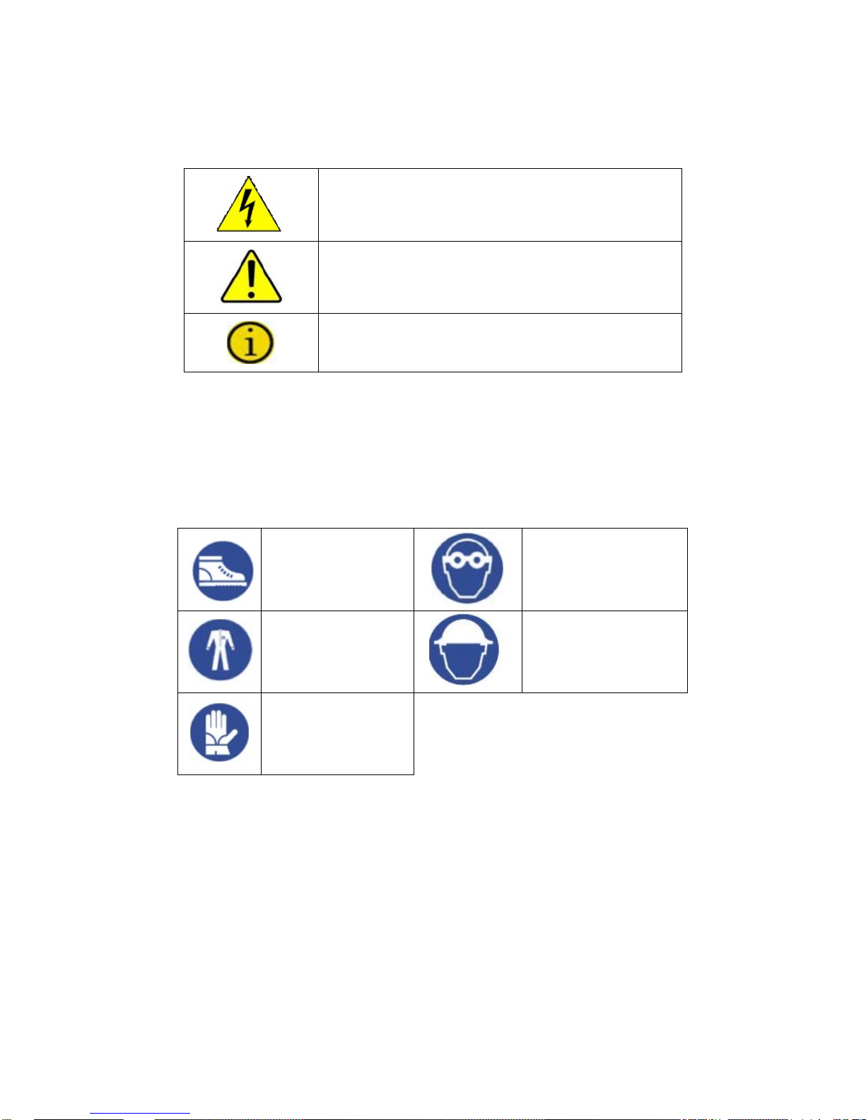
Symbols used in the Manual
Danger / Risk of Electric Shock
adequate precautions are taken.
Warning
taken
In this manual, some operations are shown by graphic symbols to alert the reader to the dangerous
nature of the operations:
This symbol indicates possibility of serious injury
or substantial damage to the unit, unless
This symbol indicates important information which
must be understood and any stated precautions
Note
Protective Equipment
No maintenance operations shall be carried out on the unit without wearing the Personal Protective
Equipment (PPE) described below. Personnel involved in the installation or maintenance of the unit must
be properly clothed.
The following signs show the protective equipment that should be worn. The various items of PPE must
be selected and sized according to the nature of the hazard (particularly electrical) posed by the unit.
Accident
prevention
Protective eyewear
footwear
Protective
clothing
Helmet
Work gloves
General Precautions
This manual contains detailed instructions for the use, installation and start-up of the UPS. Read the
manual carefully before installation. For information on using the UPS, the manual should be kept close
at hand and consulted before carrying out any operation on the UPS.
This UPS has been designed and manufactured in accordance with the standards for the product, for
normal use and for all uses that may reasonably be expected. It may under no circumstances be used for
any purposes other than those envisaged, or in any other ways than those described in this manual. Any
interventions should be carried out in accordance with the criteria and the time-frames described in this
manual.
Page | v
Page 6

Table of Contents
Applicability .............................................................................................................................................. iii
Safety Warnings ...................................................................................................................................... iii
Emergency Interventions ......................................................................................................................... iv
First aid interventions ........................................................................................................................... iv
Firefighting measures ........................................................................................................................... iv
Symbols used in the Manual ..................................................................................................................... v
Protective Equipment ................................................................................................................................ v
General Precautions ................................................................................................................................. v
1. Layout .................................................................................................................................................. 1
1.1 Views .............................................................................................................................................. 1
1.2 Preliminary Operations ................................................................................................................... 3
1.2.1 Removing the Packaging and Positioning the Device .............................................................. 3
1.2.2 Storage .................................................................................................................................... 3
1.2.3 Handling .................................................................................................................................. 3
1.2.4 Cooling of the Premises ........................................................................................................... 4
2. Installation ............................................................................................................................................ 5
2.1 Accessing the UPS terminals ......................................................................................................... 5
2.2 UPS - Single Module Configuration ................................................................................................ 6
2.3 Cable Entry ..................................................................................................................................... 7
2.4 Connect of Power Cables ............................................................................................................... 9
2.4.1 Input Line without Neutral ........................................................................................................ 9
2.4.2 Single Input ............................................................................................................................ 10
2.4.3 Connection of Power Cables for Dual input Unit ..................................................................... 12
2.5 Differential (GFI) ........................................................................................................................... 14
2.6 Emergency Power off Device (EPO) ............................................................................................. 14
2.7 Connection of Signals and Remote Commands ........................................................................... 15
2.7.1 Remote Commands, Alarms and EPO ................................................................................... 17
2.7.2 RS232-1 and RS232-2 ........................................................................................................... 18
2.7.3 SLOT 1 and SLOT 2 .............................................................................................................. 19
2.7.4 Optional Remote Alarm Cards ............................................................................................... 19
2.7.5 Optional MODEM ................................................................................................................... 20
2.7.6 Option a l MULTI I / O .............................................................................................................. 20
2.7.7 Optional Battery Temperature Sensor .................................................................................... 20
2.7.9 Multi Panel ............................................................................................................................. 20
2.7.10 SWOUT and SWMB aux. ..................................................................................................... 21
3. Operation ........................................................................................................................................... 23
3.1 Start up ......................................................................................................................................... 24
3.1.1 Before S tart Up ...................................................................................................................... 24
3.1.2 Start-Up Procedure Single Module ......................................................................................... 24
3.2 Single UPS and Load Shutdown ................................................................................................... 25
3.3 Transfer to Bypass/Inverter .......................................................................................................... 25
3.4 Operating Modes .......................................................................................................................... 25
3.4.1 On-line Factory Setting .......................................................................................................... 25
Page | vi
Page 7

3.4.2 Standby-On / Smart Active ..................................................................................................... 25
3.4.3 Standby-Off (with Mains Present the Load is not Powered) ................................................... 26
3.4.4 Stabilizer (Operation In On-Line Mode Without Battery) ......................................................... 26
4. Control Panel and Display .................................................................................................................. 27
4.1 Signal panel functions .................................................................................................................. 27
4.2 Graphic Display ............................................................................................................................ 29
4.2.1 Diagram Items Shapes........................................................................................................... 30
4.2.2 Keys Numbers and Icons ....................................................................................................... 30
4.3 Basic menu (text lines area) ......................................................................................................... 31
4.3.1 The First Line of the Basic Menu ............................................................................................ 31
4.3.2 The Second Line of the Basic Menu....................................................................................... 32
4.4 Language setting menu (keys 1, 1) ............................................................................................... 33
4.5 Measurements menus (key 2) ...................................................................................................... 34
4.6 Full page Measurements and output waveforms (key 2, 7) ........................................................... 36
4.7 Controls Menu (key 3) .................................................................................................................. 37
4.7.1 Battery Test (Keys 3, 2) ......................................................................................................... 37
4.7.2 Customizing ........................................................................................................................... 38
4.7.3 "Recorder": Recorded Events (key 4) ..................................................................................... 48
4.7.4 Disabling the Audible Alarm (key 5) ....................................................................................... 50
4.7.5"Clock": Date/Time (key 6) ...................................................................................................... 51
4.7.6 "Arrow Down": Internal Codes, Firmware Ver.(key 7) ............................................................. 51
5. UL924 Emergency Lighting Systems ............................................................................................... 52
6. Maintenance ...................................................................................................................................... 53
6.1 Periodic Maintenance (to be carried out by trained personnel and with doors closed) .................. 53
6.2 Maintenance Inside the UPS (factory authorized personnel only) ................................................. 53
6.3 Ordinary Maintenance for Batteries (trained personnel only) ........................................................ 53
6.4 Recommended Replacement Intervals ......................................................................................... 54
7. Specifications ..................................................................................................................................... 55
7.1 Electrical Specifications ................................................................................................................ 55
7.2 Environmental Requirements ....................................................................................................... 56
7.3 Mechanical Specifications ............................................................................................................ 56
7.4 Rated Currents ............................................................................................................................. 57
7.4.1 Input (Single Input Module) .................................................................................................... 57
7.4.2 Rectifier Input (Dual Input Module) ......................................................................................... 57
7.4.3 Bypass Input (Dual Input Module) .......................................................................................... 57
7.4.4 Output .................................................................................................................................... 57
7.4.5 Battery ................................................................................................................................... 57
7.5 Torque specifications .................................................................................................................... 58
Appendix A – Alarms ............................................................................................................................. 59
Appendix B - Optional remote commands .............................................................................................. 62
Appendix C - Parallel Configuratio n ....................................................................................................... 63
C.1 Introduction .................................................................................................................................. 63
C.2 Electrical System Set-Up ............................................................................................................. 64
C.2.1 Input ...................................................................................................................................... 64
Page | vii
Page 8

C.2.2 Ground Fault ......................................................................................................................... 64
C.2.3 Emergency Power Off Device (EPO) ..................................................................................... 64
C.2.4 External Maintenance Bypass. .............................................................................................. 65
C.3 Mains and Load Connections. ...................................................................................................... 65
C.4 Installing Parallel k it ..................................................................................................................... 66
C.4.1 Parallel Card Installation ........................................................................................................ 67
C.4.2 Parallel Card Connections ..................................................................................................... 68
C.4.3 Parallel Card RJ45 Installation .............................................................................................. 68
C.4.4 Parallel Card RJ45 Connections ............................................................................................ 69
C.5 Connection of Signals .................................................................................................................. 69
C.5.1 RJ45-flat-adapter signals parallel card. ................................................................................. 70
C.5.2 Single UPS Configured in Parallel ......................................................................................... 70
C.5.3 Two UPS’s in Parallel ............................................................................................................ 71
C.5.4 Three UPS’s in Parallel ......................................................................................................... 71
C.6 Parallel Start-up procedure .......................................................................................................... 72
C.7 Parallel Communication Troubleshooting ..................................................................................... 73
C.7.1 Normal Condition ................................................................................................................... 73
C.7.2 Single Opened Parallel Cable ................................................................................................ 73
C.7.3 Multiple Opened Parallel Cable ............................................................................................. 74
C.8 Mechanical Bypass ...................................................................................................................... 74
C.8.1 Mechanical bypass on a single unit ....................................................................................... 74
C.8.2 Mechanical bypass on the whole system ............................................................................... 75
C.9 Insertion and removal with UPS’s operating (hot swap) ............................................................... 76
C.9.1 Example of Hot Insertion ....................................................................................................... 76
C.9.2 Example of Hot Removal ....................................................................................................... 77
Page | viii
Page 9

Figures
Figure 1 - FLU cabinet front view ............................................................................................................. 1
Figure 2 - FLU-T cabinet front view.......................................................................................................... 2
Figure 3 – Single Input 1-Line ................................................................................................................. 6
Figure 4 - Dual Input 1-Line ..................................................................................................................... 6
Figure 5 – FLU bottom Cable Entry Layout .............................................................................................. 7
Figure 6 – FLU-T bottom Cable Entry Layout .......................................................................................... 8
Figure 7 - Schematic diagram: Single In put without Source Neutral ......................................................... 9
Figure 8 - Schematic diagram: Dual Input without Source Neutral ............................................................ 9
Figure 9 – FLU UPS Single Input Power Connection Terminals ............................................................. 10
Figure 10 – FLU-T UPS Single Input Power Connection Terminals ....................................................... 11
Figure 11 – FLU UPS Dual Input Power Connection Terminals ............................................................. 12
Figure 12 – FLU-T UPS Dual Input Power Connection Terminals .......................................................... 13
Figure 13 – Emergency Power Off (EPO) ............................................................................................. 14
Figure 14 – FLU Signals and Remote Command Connections .............................................................. 15
Figure 15 – FLU-T Signals and Remote Command Connections ........................................................... 16
Figure 16 – Remote Alarm Contacts ......................................................................................................
Figure 17 – RS232-2 Female Connection ............................................................................................. 18
Figure 18 – RS232-1 Male Connection ................................................................................................. 19
Figure 19 – Single Module Wrap-around bypass ................................................................................... 21
Figure 20 – Parallel System Wrap-around bypass ................................................................................. 22
Figure 21 – Single Input 1-Line .............................................................................................................. 23
Figure 22 – Dual Input 1-Line ................................................................................................................ 23
Figure 23 – Signal Panel ....................................................................................................................... 27
Figure 24 – Graphic Display .................................................................................................................. 29
Figure 25 – Typical (3) Module Parallel System .................................................................................... 63
Figure 26 – Recommended Ground Fault Interrupter Layout ................................................................ 64
Figure 27 – Parallel System EPO .......................................................................................................... 64
Figure 28 - Three units connected in parallel (Typical) .......................................................................... 65
Figure 29 – Parallel Card Installation ..................................................................................................... 67
Figure 30 – Parallel Card connections ................................................................................................... 68
Figure 31 – Parallel Card RJ45 Installation ........................................................................................... 68
Figure 32 – Parallel Card Flat Cable Installation.................................................................................... 69
Figure 33 - Parallel Control Routing ...................................................................................................... 69
Figure 34 - RJ45-flat-adapter signals parallel card ................................................................................ 70
Figure 35 – Parallel Connection – Single Module .................................................................................. 70
Figure 36 – Parallel Connection – Two Modules ...................................................................................
Figure 37 – Parallel Connection – Three Modules ................................................................................. 72
18
71
Tables
Table 1 - Torque Specifications for Terminal Blocks on Customer Interface Board ................................. 16
Table 2 - Interface Remote Command Alarms and EPO ........................................................................ 17
Table 3 - Interface Terminal Connector ................................................................................................. 22
Table 4 - Led Status Indicators .............................................................................................................. 28
Table 5 - Diagram Items Shapes ........................................................................................................... 30
Table 6 - Keys Numbers and Icons ........................................................................................................ 30
Table 7 – Battery Models approved for UL924 ....................................................................................... 52
Table 8 – UL924 Approved Systems ...................................................................................................... 52
Table 9 - Recommended Replacement Intervals ................................................................................... 54
Table 10 – Parallel Kit Components ...................................................................................................... 66
Page | ix
Page 10

Page | x
Page 11
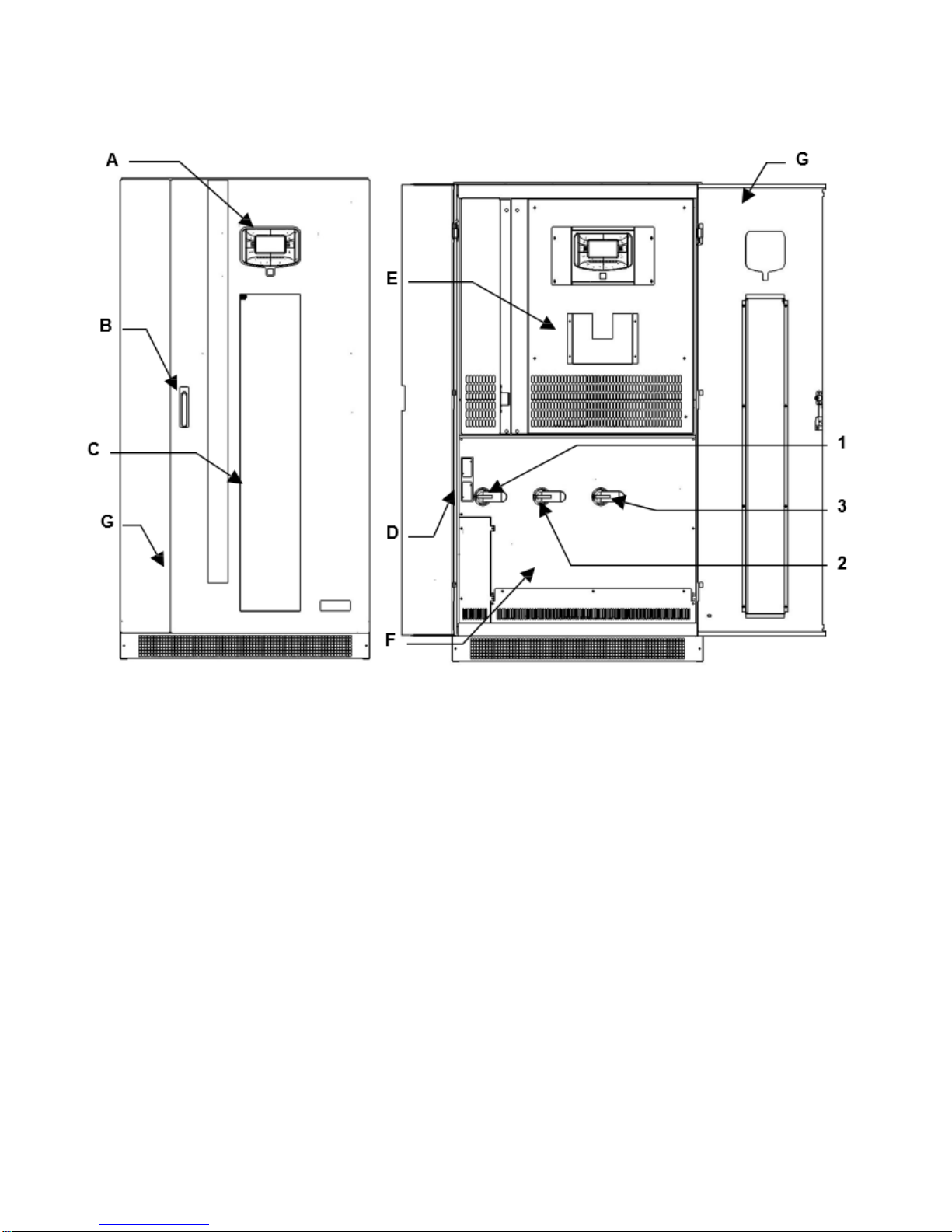
1. Layout
1.1 Views
Figure 1 - FLU cabinet front view
A - Control Panel with Graphic Display
B - Door Handle
C - Ventilation Grilles
D - Communication Area
E - Front Cover Panel with Ventilation Grilles
F - Switch Cover Panel
G - Door
1 - SWIN: Input Power Switch
2- SWBY: Static Switch Bypass Input
3 - SOUT: Static Switch Output
Page | 1
Page 12
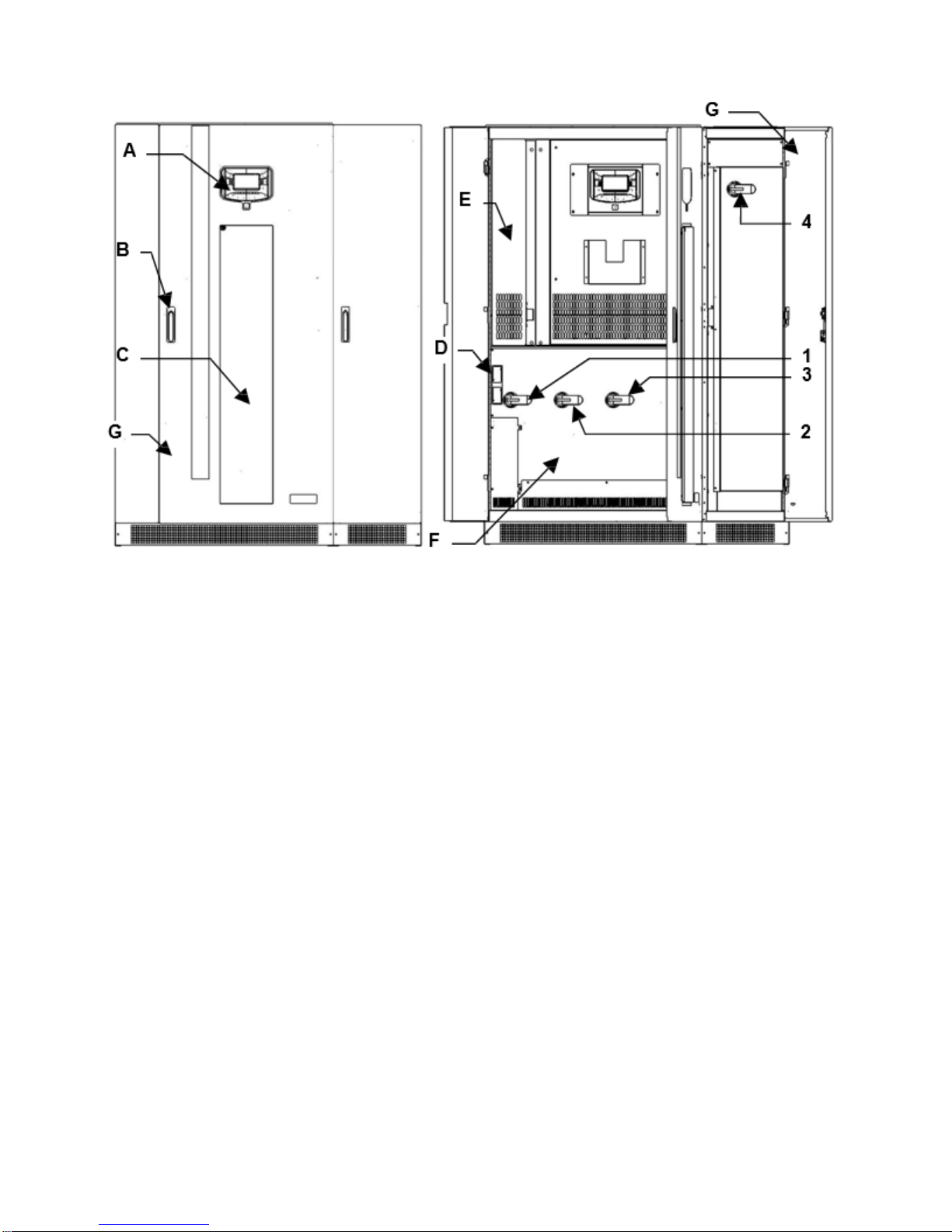
Figure 2 - FLU-T cabinet front view
A - Control Panel with Graphic Display
B - Door Handle
C - Ventilation Grilles
D - Communication Area
E - Front Cover Panel with Ventilation Grilles
F - Switch Cover Panel
G - Door
1 - SWIN: Input Power Switch
2 - SWBY: Static Switch Bypass Input
3 - SOUT: Static Switch Output
4 - SWMB: Mechanical Bypass Switch
Page | 2
Page 13
1.2 Preliminary Operations
DANGER
1.2.1 Removing the Packaging and Positioning the Device
On delivery, the packaging must be inspected to ensure that it is whole and that it has not been crushed
or dented. Check in particular that neither of the two impact resistant devices on the packaging is red; if
one of them is red; follow the instructions on the packaging.
The essential details of the device are provided on the shipping document. The marking, weight and
dimensions of the various items making up the packing list are shown.
Check the state of the device by means of a visual inspection of both the inside and the outside. Any
dents seen mean that it has suffered shocks during shipping, which could compromise the normal
operation of the device.
1.2.2 Storage
Place the device in covered premises that are protected from direct contact with atmospheric agents and
dust. The following environmental values are those allowed in the storage area:
Temperature: -13°F to +167°F (-25 to + 75 °C)
Relative humidity: 30-95 % max.
WARNING
For the installation of a battery cabinet, if provided with the uninterruptible power supply, follow
the instructions given in the specific manual.
The list of material provided may vary depending on the order specifications. Most systems include the
following: this manual, the installation drawing, the warranty and eventual accessories.
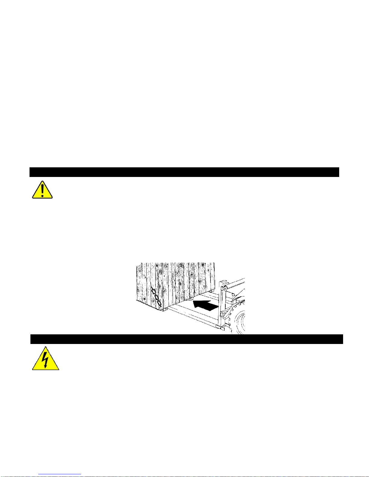
1.2.3 Handling
The equipment must only be handled by adequately trained personnel.
1 Insert the forks of the fork-lift truck in the lower part of the device, from the front or back, and
ensure that they stick out about 12 inches on the other side.
2 Secure the device to the fork-lift before moving it.
In order to avoid the risk of the device overturning, ensure that it is firmly secured to the
fork-lift truck by means of appropriate ropes before moving it.
When being moved the cabinet should be handled with care; shocks or drops can damage it. Once in
position, remove the packaging carefully in order not to scratch the device.
The packaging should be removed as follows:
1. Cut the bands
2. Slide away the carton from above.
Page | 3
3. Remove the screws securing the cabinet to the wooden base.
Page 14
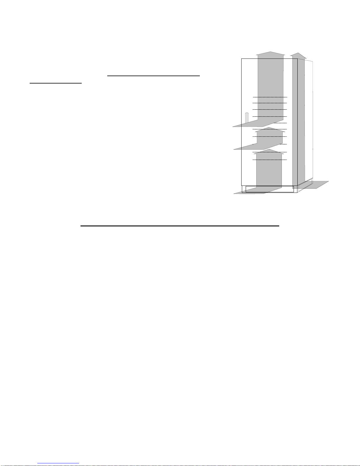
1.2.4 Cooling of the Premises
The recommended operating temperature for the lifetime of the UPS
and of the batteries is between 20 and 25°C. The lifespan of the
battery depends on the operating temperature; with an operating
temperature increase from 20°C to 30°C, the lifespan of the
batteries is halved.
The airflow inside UPS is by the fans located inside the UPS (forced
convection) and by the air around the side panels (natural
convection).
In order to ensure proper air circulation measures must be taken
during installation to avoid any obstructions to the free circulation of
air. These include the following:
• Ensure a distance of at least 24 inches from the ceiling, so as
not to hinder air extraction,
• Leave a free space of at least 36 inches at the front of the
equipment to ensure both the circulation of the air and
installation and maintenance operations;
• With natural convection the thermal load is dissipated to the
outside through the walls; thus a cabinet placed against a wall or in a hollow dissipates less heat than
one located in a free environment.
The following rule must be observed:
Leave at least one of the three side walls free: right, left or back.
• The bottom side kick panels must not be mounted for installations where cabinets are placed side by
side.
Page | 4
Page 15

2. Installat ion
DANGER
• Check the Safety Instructions.
• Any incorrect connection or handling may cause damage to the UPS and/or the loads
connected to it. Read these instructions carefully and follow the steps indicated.
• This UPS must be installed by qualified electrician.
• It is advisable to provide a maintenance bypass switch or an electrical panel with individual
protection for input, output, and static bypass, as well as a manual bypass. This allows isolation
of unit during preventive maintenance or repair.
2.1 Accessing the UPS terminals
The following operations must be performed while the UPS is disconnected from the utility
mains power, switched off and all the input and output power switches on the equipment are
open. Before performing connection, open all the input and output power switches and
check that the UPS is completely isolated from all power sources: battery and AC power
line. In particular, check that:
- UPS input line is completely isolated;
- Batt er y circuit breaker/disconnect is open;
- All UPS power and load connection switches (SW IN, SWBY, SWOUT and SWMB) are
in the open position;
- No dangerous voltages are present (use a multimeter).
The first connection to be performed is the protective wire (earth ground cable) which has to
be inserted into the terminal labeled PE. The UPS must operate with the grounding system
connected.
WARNING
• Do not connect the output neutral to the input neutral.
• If the input connection is Delta the UPS can supply only Delta load.
• The output neutral must not be connected unless the UPS is the Wye version supplied
with an input neutral.
• TRANSFORMER BOXES (optional) are available for converting the distribution
systems from 3 to 4 wires.
• If a three-phase non-linear load is connected to the output, the current on the neutral
conductor can reach a value equal to 1.5 times the value of the phase current.
Dimension the input/output neutral cable appropriately taking this fact into account.
• The UPS cannot feed from a corner ground or mid-point grounded delta supply
source.
• Use only lugs or cables with tin-plated eyes for the connections.
• Ensure correct phase rotation at the input and output terminals
• Ensure correct polarity battery connections
The DC input requires a disconnect means which is provided in most Staco supplied battery
cabinets.
AC and DC cables and cable lugs are to be provided by others as part of the UPS installation
Page | 5
Page 16

Each model can be configured for a delta input source with a delta connected load or for a wye
input with a wye connected load. If the load requires a neutral connection (i.e. wye), then an
input neutral must be provided. Refer to the Power Connection terminals diagrams later in this
section for details concerning configuration of the neutral to ground bond.
2.2 UPS - Single Module Configuration
The UPS is designed to work as Single input Unit or as Dual input Unit.
Figure 3 – Single Input 1-Line
Figure 4 - Dual Input 1-Line
Page | 6
Page 17
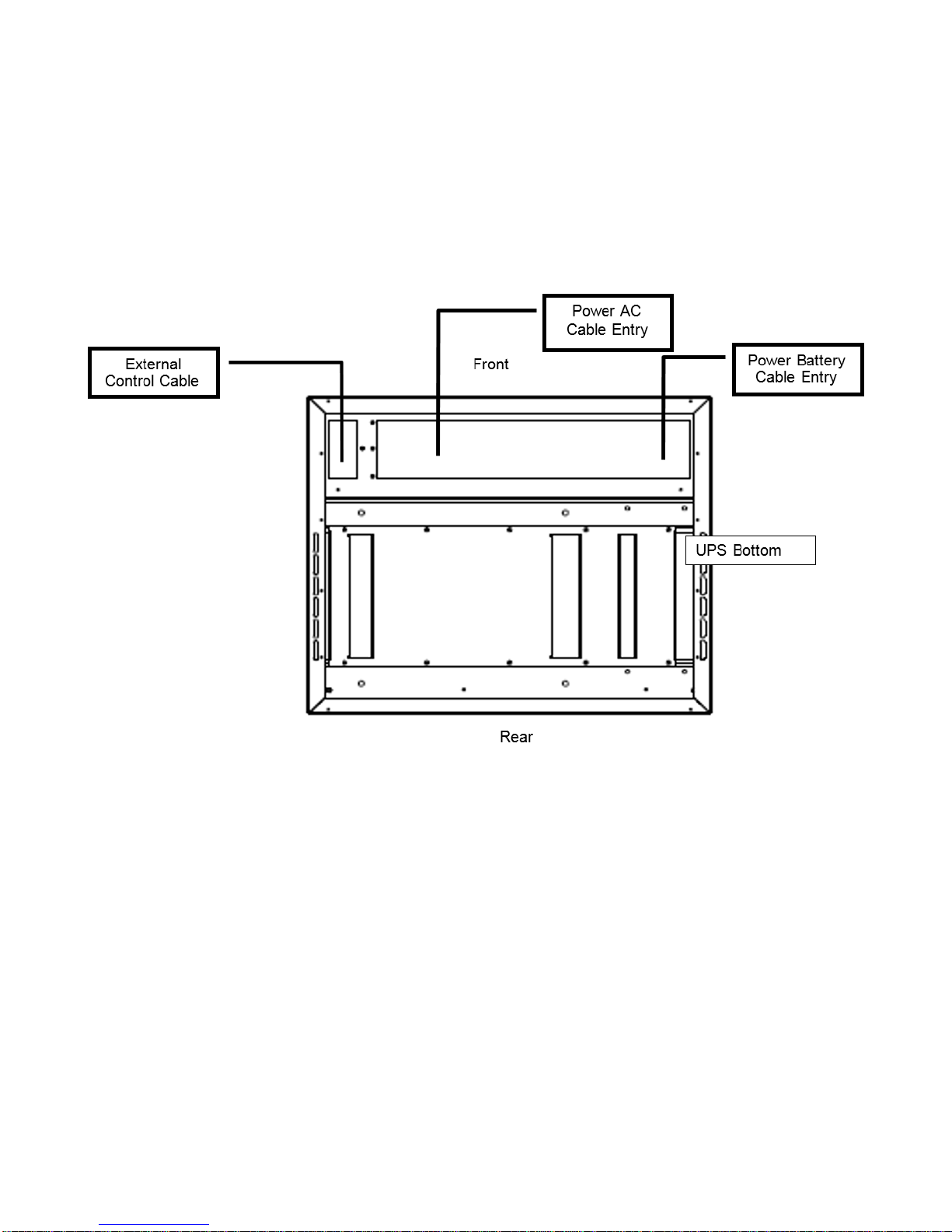
2.3 Cable Entry
The cables can enter in the UPS from the bottom or from the top with the optional (Top Entry Cabinet)
Proceed as follows in order to open the UPS
1. Open the door
2. Remove the switch cover panel
3. Remove the bottom cable entry cover plates
4. Drill or punch conduit holes in the cover plates
5. Route the power cable through the bottom to the UPS terminals in base to your configuration
(see Figure 5 and Figure 6)
Page | 7
Figure 5 – FLU bottom Cable Entry Layout
Page 18
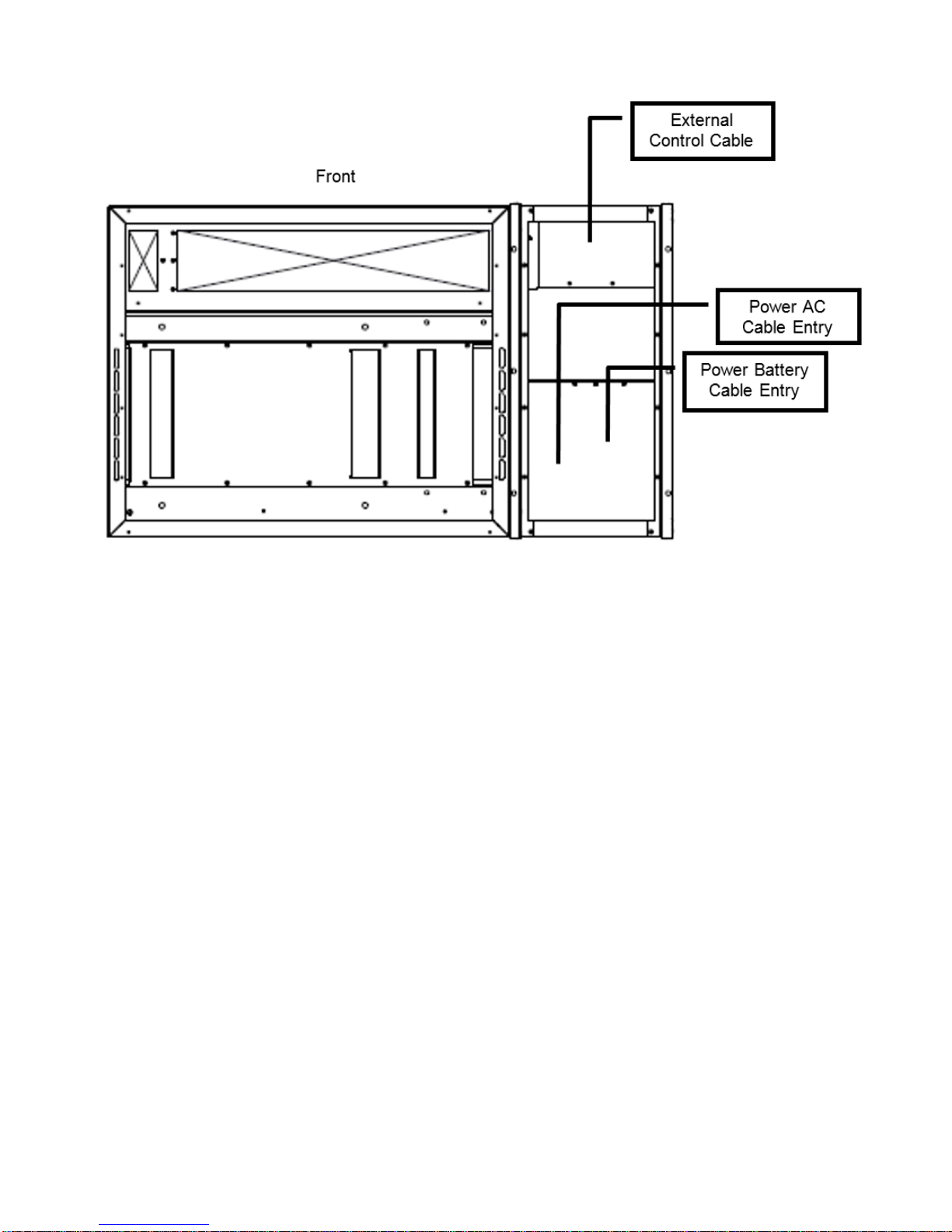
Figure 6 – FLU-T bottom Cable Entry Layout
Page | 8
Page 19
2.4 Connect of Power Cables
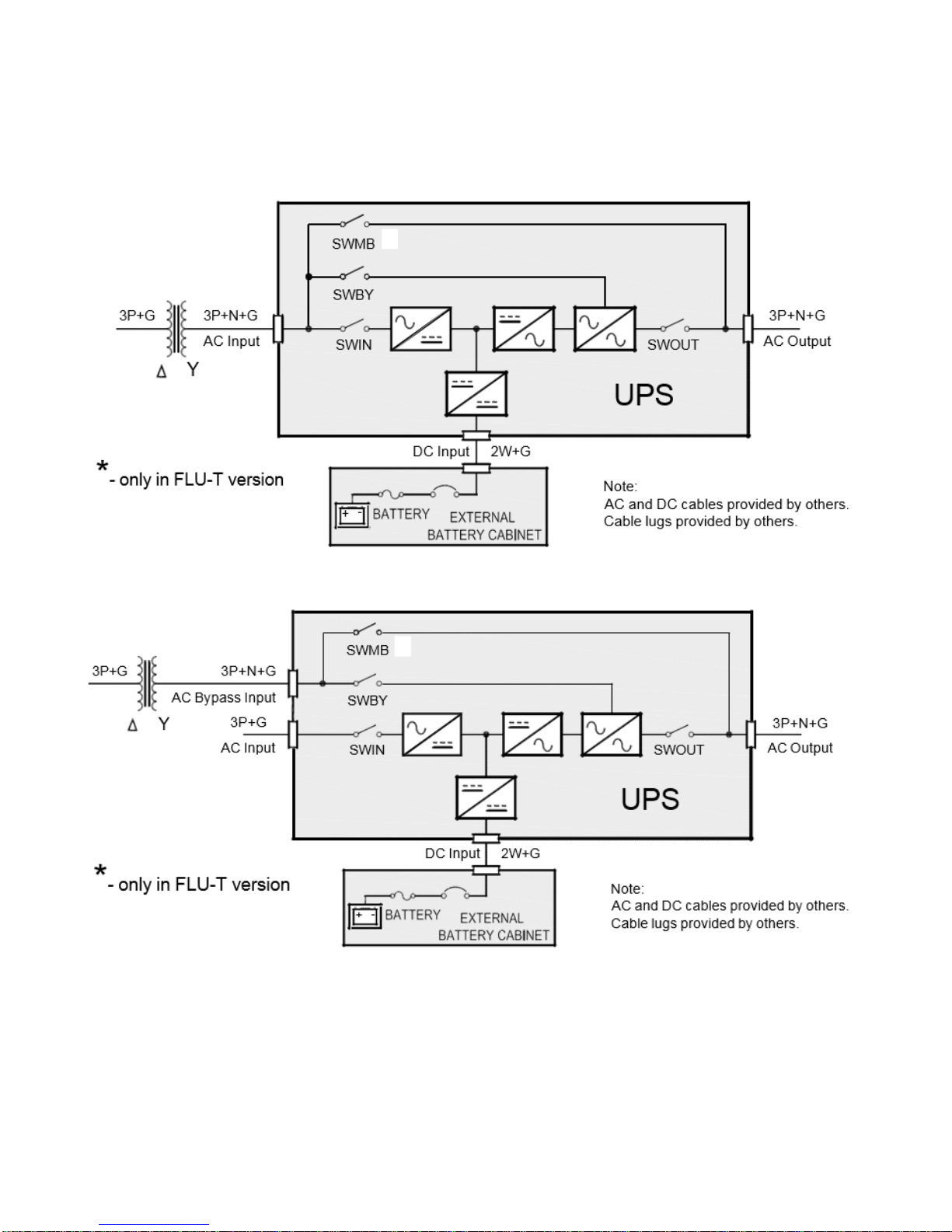
2.4.1 Input Line without Neutral
If utility is a 3-wire source and the load requires a neutral, a transformer must be inserted either on the
mains supply line or on the bypass line.
Figure 7 - Schematic diagram: Single Input without Source Neutral
Figure 8 - Schematic diagram: Dual Input without Source Neutral
Page | 9
Page 20
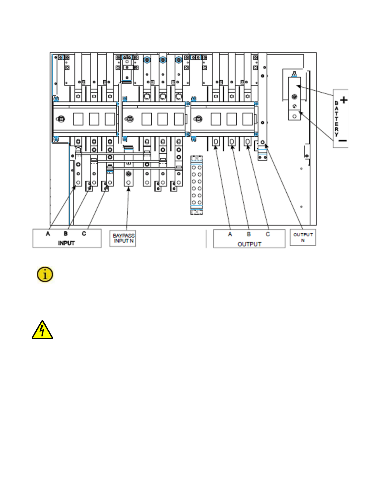
2.4.2 Single Input
Connect the input, output and battery cables to the terminals as shown in Figure 9 and Figure 10:
Figure 9 – FLU UPS Single Input Power Connection Terminals
For the Input, Output and Battery connections, follow the order from the top to bottom, or
right to left, as described in the boxes. The label marked “N” present on the terminal
identifies the neutral terminal.
The single input is a factory default configuration. Do not remove the bypass jumper. The input phase
connections are made using bolts to one of the three holes in the busbar. Do not loosen the bolts that
attach the busbar.
The UPS is provided with a separate busbar that connects the Neutral Output to the frame
Ground for delta input connection. This is required to meet NEC grounding code for separately
derived neutrals. When a Neutral is provided in a Wye configured input connection the busbar
must be removed.
Once installation has been completed inside the equipment, put the switch cover panel back and close
the door.
Page | 10
Page 21
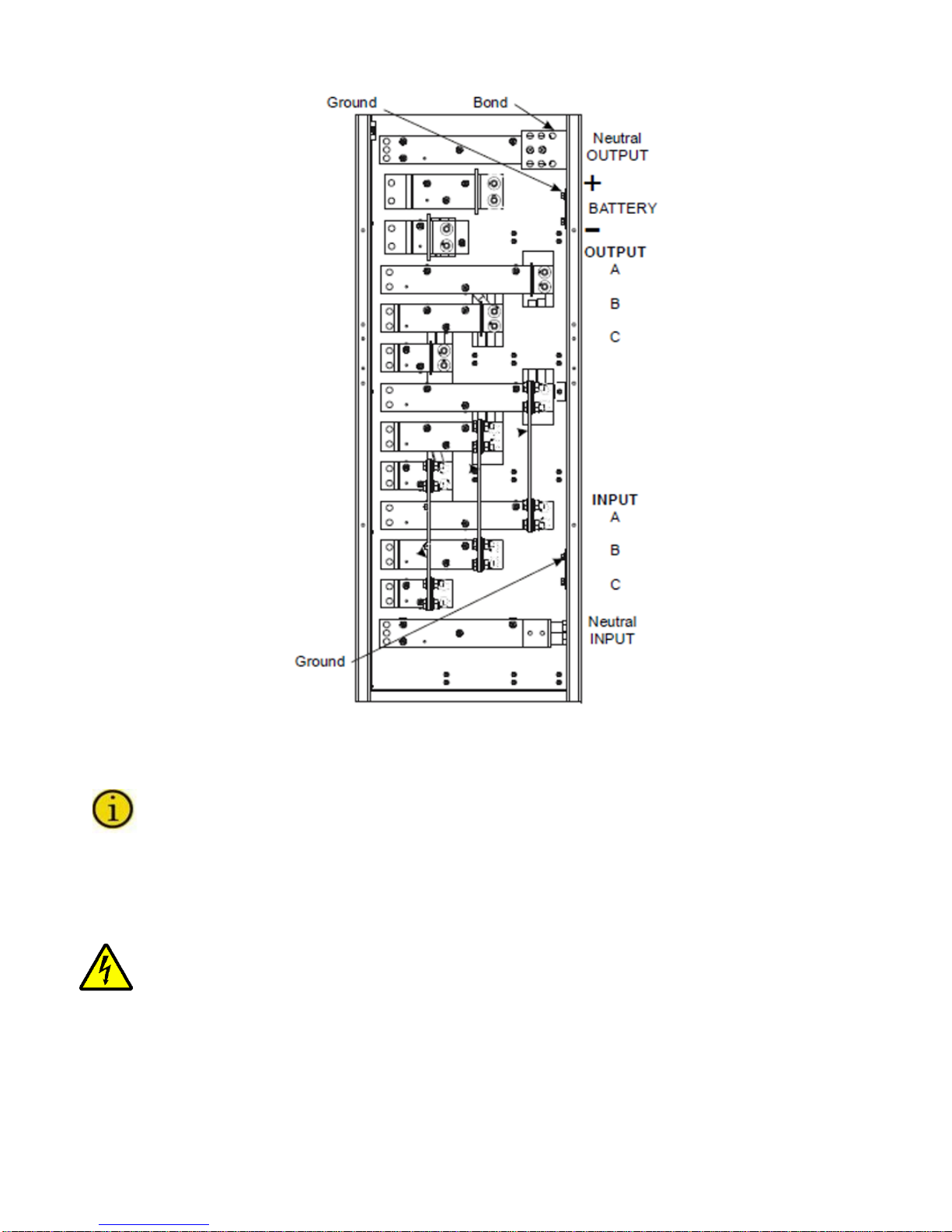
Figure 10 – FLU-T UPS Single Input Power Connection Terminals
For the Input, Output and Battery connections, follow the order from the top to bottom, or right
to left, as described in the boxes. The label marked “N” present on the terminal identifies the
neutral terminal.
The single input is a factory default configuration. Do not remove the bypass jumper. The input phase
connections are made using bolts to one of the three holes in the busbar. Do not loosen the bolts that
attach the busbar.
The UPS is provided with a separate busbar that connects the Neutral Output to the frame
Ground for delta input connection. This is required to meet NEC grounding code for separately
derived neutrals. When a Neutral is provided in a Wye configured input connection the busbar
must be removed.
Once installation has been completed inside the equipment, put the switch cover panel back and close
the door.
Page | 11
Page 22
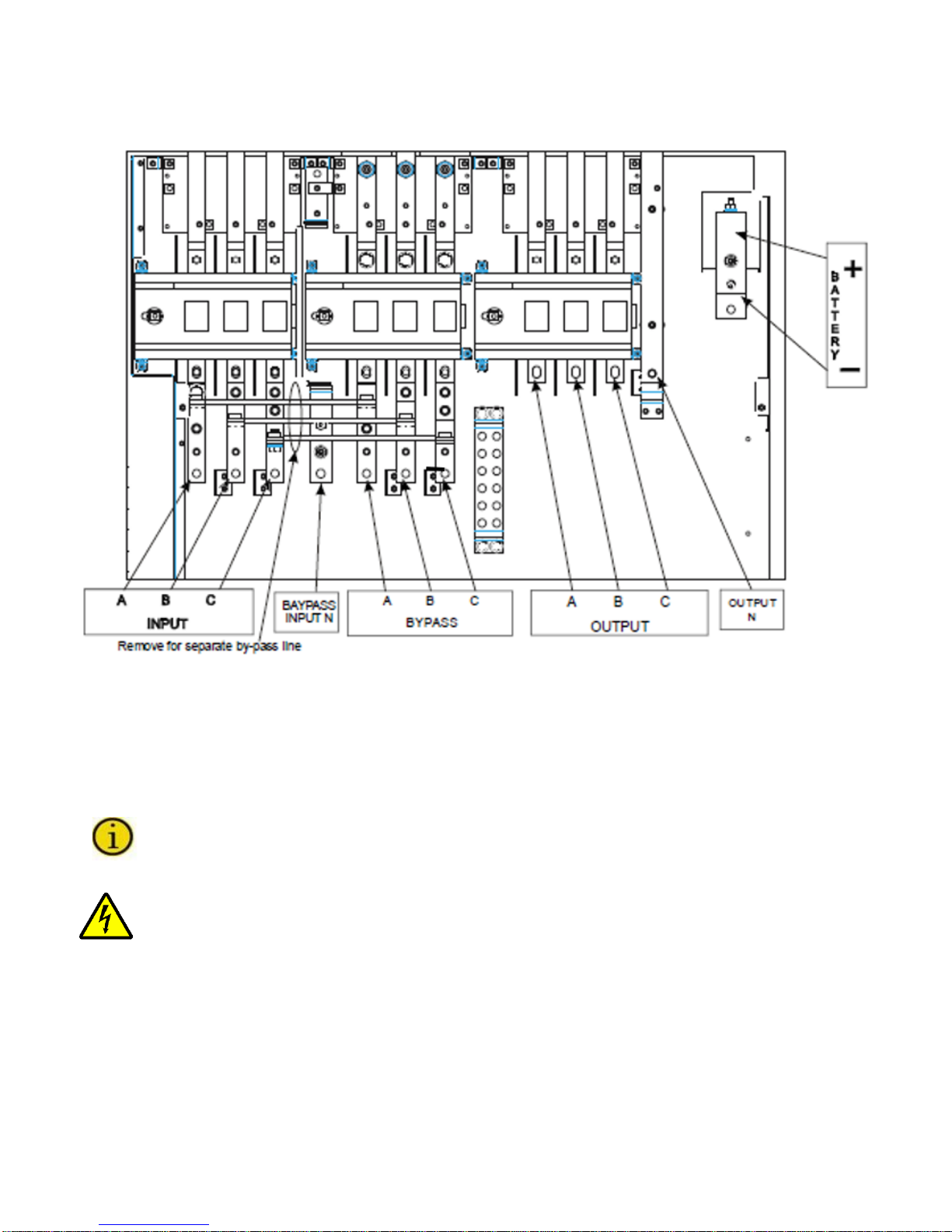
2.4.3 Connection of Power Cables for Dual input Unit
Connect the input, bypass, out put and battery cables to the terminals as shown in Figure 11 and
Figure 12
Figure 11 – FLU UPS Dual Input Power Connection Terminals
The single input is a factory default configuration. Remove the jumpers present between the SWIN
and SWBY. The input phase connections attach using bolts through the holes that were previously
used to attach the busbars. The main (rectifier) input is located on the left and the bypass input is on
the right. The neutral input comes from the bypass source; no neutral is to run to the rectifier input
source, although the rectifier source must be a grounded wye.
For the Input, Bypass, Output and Battery connections, follow the order from the top to bottom,
or right to left, as described in the boxes. The label marked “N” present on the terminal
identifies the neutral terminal.
The UPS is provided with a separate busbar that connects the Neutral Output to the frame
Ground for delta input connection. This is required to meet NEC grounding code for separately
derived neutrals. When a Neutral is provided in a Wye configured input connection the busbar
must be removed.
Once installation has been completed inside the equipment, put the switch cover panel back and close
the door.
Page | 12
Page 23
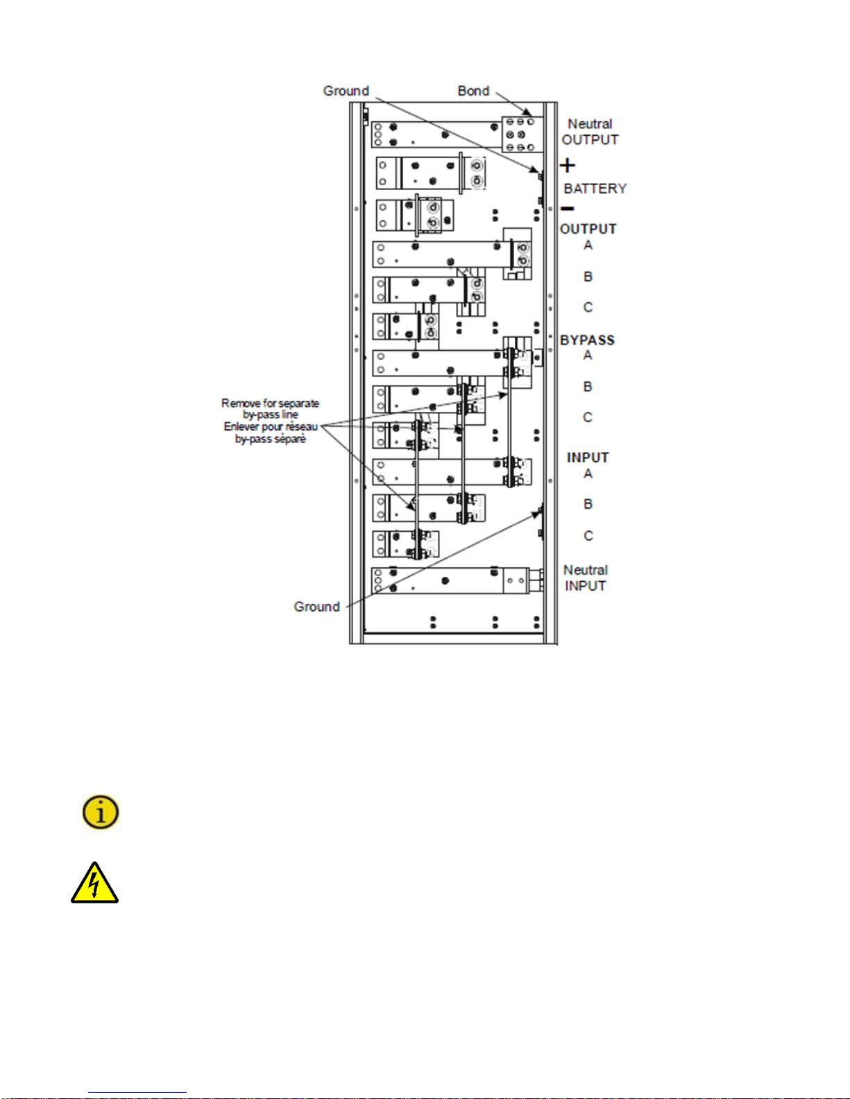
Figure 12 – FLU-T UPS Dual Input Power Connection Terminals
The single input is a factory default configuration. Remove the jumpers present between the SWIN
and SWBY. The input phase connections attach using bolts through the holes that were previously
used to attach the busbars. The main (rectifier) input is located on the left and the bypass input is
on the right. The neutral input comes from the bypass source; no neutral is to run to the rectifier
input source, although the rectifier source must be a grounded wye.
For the Input, Bypass, Output and Battery connections, follow the order from the top to bottom,
or right to left, as described in the boxes. The label marked “N” present on the terminal
identifies the neutral terminal.
The UPS is provided with a separate busbar that connects the Neutral Output to the frame
Ground for delta input connection. This is required to meet NEC grounding code for separately
derived neutrals. When a Neutral is provided in a Wye configured input connection the busbar
must be removed.
Once installation has been completed inside the equipment, put the switch cover panel back and close
the door.
Page | 13
Page 24
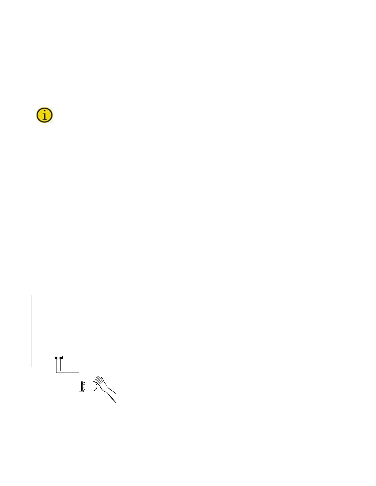
2.5 Differential (GFI)
UPS
a
b
a - EPO terminal board located on the UPS
b - EPO switch (not provided).
If the UPS protection against electric shock uses a differential current device (Ground Fault Interrupter),
it will have to have the following characteristics:
• Sensitivity 300mA
• Sensitive direct current and unidirectional components (class A or class B)
• Insensitive to transient cur r ent pulses
• Delay greater than or equal to 0.1 s.
In the standard version without an isolation transformer on the bypass line, the neutral from
the mains power supply is connected to the output neutral of the UPS.
THE ELECTRICAL SYSTEMS UPSTREAM AND DO WNSTREAM OF THE UPS MUST BE
EXACTLY THE SAME (DELTA-DELTA or WYE-WYE)
When operating in the presence of mains supply, a differential breaker (GFI) insta l led on the input will
intervene as the output circuit is not isolated from the input cir cuit.
When operating without mains supply (from battery) the input differenti al breaker will intervene only if it
is able to switch as a result of leakage current without any voltage at its poles (for example a
differential breaker with an auxiliary relay is not suitable). However it is possible to install additional
differential breakers on the output of the UPS possibly coordinated with those on the input.
2.6 Emergency Power off Device (EPO)
The UPS has an EPO (Emergency Power Off) function. In the event of an em er gency, using this
function will cause the UPS to shut down the rectifier, inverter, and static switch and completely
disconnect the power to the load. The Output circuit of the UPS should not be considered safe, unless
the UPS is Off and the input power source to the UPS has been removed by opening the input
disconnect devices which are external to the UPS, including the battery.
This function can be activated from the button (under a hinged clear plastic cover) on the control panel
or by a remote contact. This button must be depressed and held down until the UPS shuts down. On
the UPS, the jumper on the EPO terminals must be removed, and the wires from the auxiliary contact
of the button must be connected in place of the jumper. The contact must be closed with the button in
the rest position and must open when the button is pressed.
Figure 13 – Emergency Power Off (EPO)
Page | 14
Page 25
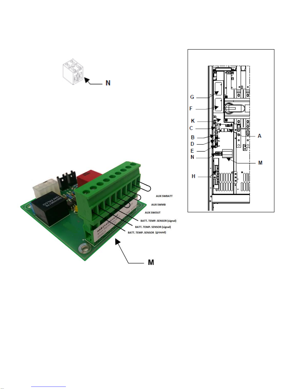
2.7 Connection of Signals and Remote Commands
A-
Parallel
N-
Terminal Block
In order to access the interface cards, open the door and remove the protection panel secured with
screws (K) as shown in the drawing:
B-
EPO (Emergency Power Off control)
C-
Remote Commands and Alarms
D-
RS232-2
E-
RS232-1
F-
Slot 2 (Main)
G-
Slot 1 (Main)
H-
Remote Alarms (Optional)
M-
Aux Signals Isolation Board
Figure 14 – FLU Signals and Remote Command Connections
Page | 15
Page 26

AWG Wire size range
Torque Load
A-
Parallel
B-
EPO (Emergency Power Off control)
C-
Remote Commands and Alarms
D-
RS232-2
E-
RS232-1
F-
Slot 2 (Main)
G-
Slot 1 (Main)
H-
Remote Alarms (Optional)
I-
Remote Alarms (Optional)
M-
Aux Signals Isolation Board
N-
Terminal Block
Figure 15 – FLU-T Signals and Remote Command Connections
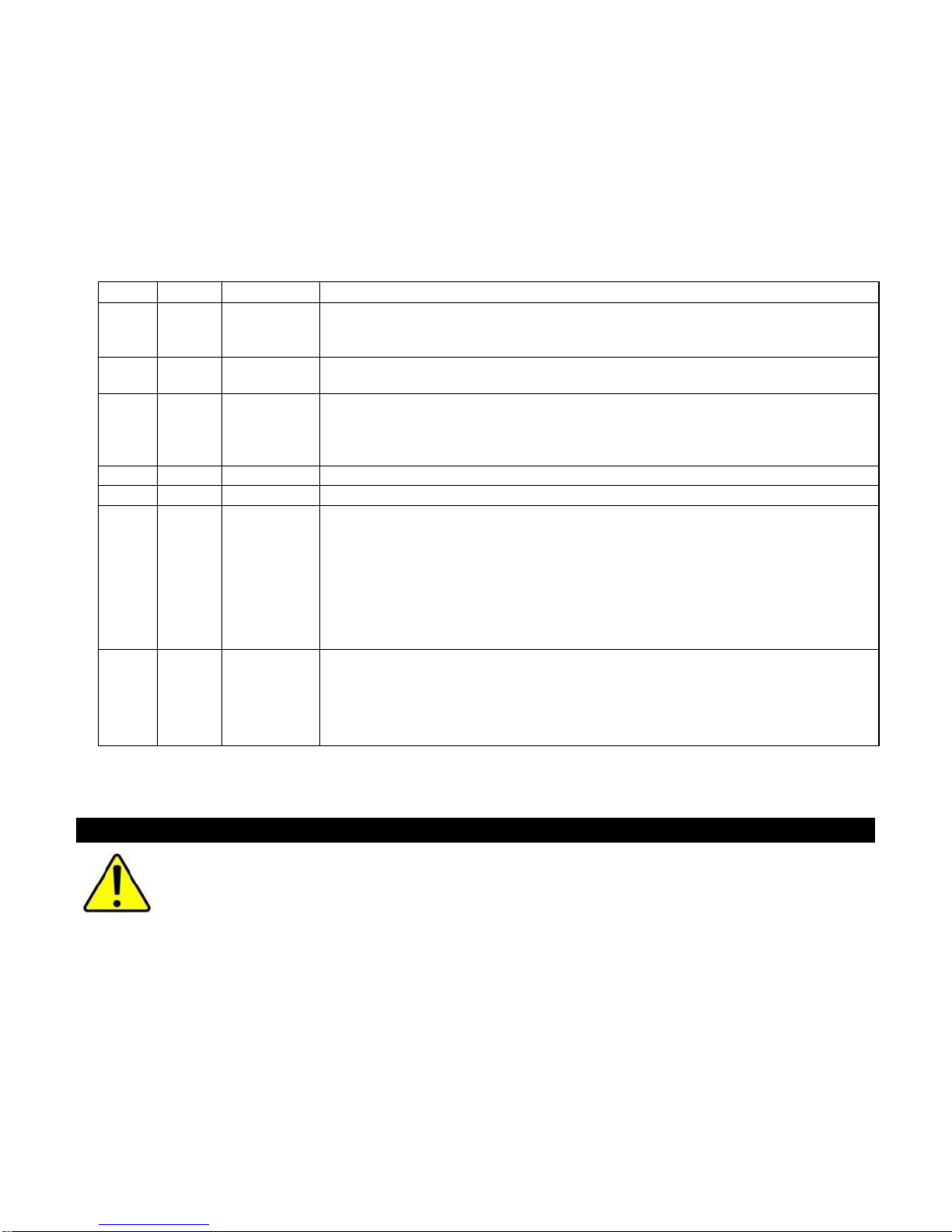
Table 1 - Torque Specifications for Terminal Blocks on Customer Interface Board
Page | 16
#22 -12AWG 4.4 lbf-ft
6 Nm
Page 27
PIN
NAME
TYPE
FUNCTION
Bypass / fault, the contact changes position when the UPS switches the load
a result of a fault in the inverter stage. See Note 1
Battery discharging, the contact changes position when the load is powered
from the battery due to a mains power failure
End of battery discharge, the contact changes position when, during a mains
factory-set end of discharge pre-alarm value is 5 minutes)
10
+12V
POWER
Power supply +12Vdc 80mA (max.) [pins 10 and 11]
11
GND
POWER
Inverter OFF. Connect pin 11 to pin 12 (for at least 2 seconds).
not powered). See Note 1
If the jumper on the connector is opened, the voltage on the UPS output will be
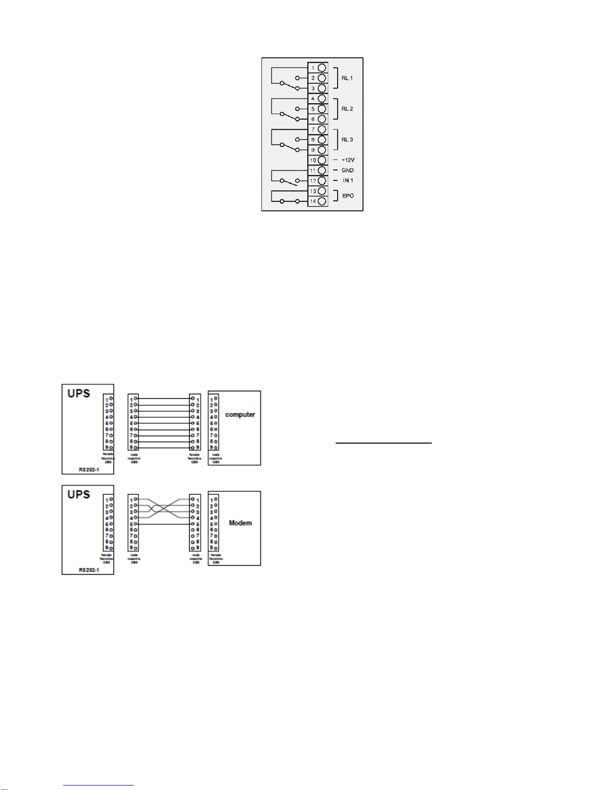
2.7.1 Remote Commands, Alarms and EPO
The card is equipped with a terminal board with 14 positions.
Power Supply - 1 power supply 12Vdc 80mA (max.) [Pins 10 and 11];
Alarms - 3 potential-free change-over contacts for alarms (they are capable of switching up to 30 V
AC or DC at UP to 1 A);
Command - 1 command programmable from the panel [Pins 11 and 12]
Table 2 - Interface Remote Command Alarms and EPO
1,2,3
4,5,6
7,8,9
12
13,14
Note 1: If the UPS installation includes a Staco Maintenance Bypass Switch (MBS) Cabinet, this connection is
RL 1 OUTPUT 1
RL 2 OUTPUT 2
RL 3 OUTPUT 3
IN 1 INPUT 1
EPO
required to be connected to the MBS and is not available for other use. An Optional Remote Alarm
interface can be installed if a second function is required in this case.
INPUT
EPO
onto the bypass line either during normal operation (e.g. due to overload) or as
outage, the remaining time for battery discharge has reached the minimum
value defined. Once this time has passed, the load will remain unpowered (the
-
In “NORMAL OPERATION”,
If the INVERTER OFF command is received, the UPS switches the power
supply of the load onto the bypass line (load is not protected should there be a
mains outage).
-
In “EMERGENCY OPERATION”,
If the STOP INVERTER command is received, the UPS shuts down (load is
cut.
The UPS is factory-fitted with the EPO terminals short circuited. If this input is
used, the UPS can be shut down in a hazardous situation from a remote
position simply by pressing a button.
WARNING
If only the mains power supply is removed, for example by opening the switch of the
power supply panel, as a means to shut down the UPS in an emergency the UPS will
keep the load powered using the energy in the batteries.
The functions of the three contacts and the command may be reprogrammed via the display panel.
The ALARMS and the COMMAND are factory-set. The position of the contacts as shown is without
the alarm present. The contacts can take a maximum cur rent of 1A with 24Vac.
Page | 17
Page 28
DB9 female RS232-2
Figure 16 – Remote Alarm Contacts
2.7.2 RS232-1 and RS232-2
2 DB9 connectors are available for RS232 connection. The factory-set transmission protocol is:
9600 baud, -no parity, -8 bits, -1 stop bit.
The transmission speed may be varied from 1200 to 9600 baud, using the PERSONALIZATIONS menu
on the CONTROL PANEL. Depending on the distance of transmission, the recommended values for the
transmission speed are:
• 9600 baud 50m
• 4800 baud 100m
• 2400 baud 200m
• 1200 baud 300m
See the diagrams below for the connection procedure.
For connection with a computer,
use a standard RS 232 cable. See
the diagram for connection with a
modem.
Figure 17 – RS232-2 Female Connection
Page | 18
Page 29

DB9 female RS232-1
For connection with a computer,
use a standard RS 232 cable. See
the diagram for connection with a
modem.
Figure 18 – RS232-1 Male Connection
2.7.3 SLOT 1 and SLOT 2
Following Cards May be Inserted (Optional):
NetMan 102 Plus (in SLOT 1 main or SLOT 2 aux)
Device for management of the UPS’s on the Ethernet. It can send information on the status of the
device with various protocols:
• TCP/IP UDP (compatible with Watch&Save);
• SNMP (for communications with NMS or with PowerNETGuard);
• HTTP (to display the status with a browser);
• TFTP (to configure or update the device when connected to the network).
The main function of this device is to integrate the UPS into the LAN network ensuring a high level of
reliability of communication with the server to enable full management and control of the UPS.
MULTICOM card (in SLOT 1 m ain or SLOT 2 aux)
This device may be used to:
• add a serial port to the UPS;
• monitor the UPS using MODBUS/JBUS protocol on RS485 or PROFIBUS (Multicom 401)
Note: each card connected precludes the use of a standard RS232 port, as follows.
• The use of SLOT 1 (main) inhibits the use of RS232-2
• The use of SLOT 2 (aux) inhibits the use of RS232-1
For the full and updated list of communication accessories, please see the website
www.stacoenergy.com
2.7.4 Optional Remote Alarm Cards
6 outputs: potential-free contacts for alarms
• Programmable from the display panel;
• Capable of switching up to 30 V AC or DC at UP to 1 A;
(2) Inputs
• Programmable from the panel;
• (1) 12V DC maximum 100mA auxiliary input.
Page | 19
Page 30

2.7.5 Optional MODEM
Model compatible with the communication standards between the UPS and the software provided.
Note: the modem must be connected to an RS232 port; a standard RS232 port may not therefore be
used.
2.7.6 Optional MULTI I / O
The function of this accessory is to convert external signals from the UPS (e.g. t emperat ure of
environment, temperature of battery premises, etc.) into signals by means of relay contacts or via serial
output RS485 in MODBUS protocol. It has the following characteristics:
• 8 inputs (e.g. humidity, smoke, etc. sensors)
• communication with the UPS via serial port
• 8 relays configurable with 8 events on the UPS
• RS232 output port with configurable messages
• RS485 output port MODBUS /JBUS with configurable messages.
2.7.7 Option al Battery Temperature Sensor
The UPS has a connector for connection of the kit, which consists of a sensor to be placed inside the
battery cabinet. The use of the temperature sensor allows the UPS control logic to regulate the values of
the charge and maintenance voltage according to the working temperature of the battery.
Optional Battery Temperature Alarm
The battery temperature alarm is active only when Battery Temperature Sensor is connected. The
temperature value to start the alarm can be changed with the following procedure:
1) The following sequence of numbers must be entered into the display to access settings. Press
the front panel display buttons 3, 5, 151515, 7
2) Press 3, 5, 327171, 7 to access the battery temperature settings
3) Press key 5 or 6 as necessary to adjust the minimum battery temperature [default:0 ; range:0-10]
4) Press key 7 or 8 as necessary to adjust the maximum battery temperature [default:50 ; range 2060]
5) Press 1 to exit from the battery temperature menu
6) The alarm temperature value is now adjusted
2.7.9 Multi Panel
The Multi Panel is used to monitor the UPS from a distance and provides a detailed overview of the
module operating status. It allows the operator to consult measurements relating to mains power, output
load, batteries, etc. and also to identify any malfunctions.
The Multi Panel connects from the UPS Serial port on the Multi Panel to the RS232-1 or RS232-2 port in
the UPS. See Section 2.7.2 RS232-1 and RS232-2.
Page | 20
Page 31

2.7.10 SWOUT and SWMB aux.
Terminals to be used for connection of the auxiliary contacts of switches used for a wrap-around bypass
Note:
• Auxiliary switch of SWMB EXT must open in advance, before closing the power contact
• Auxiliary switch of SWOUT EXT must close in advance, before opening the power contact
Figure 19 – Single Module Wrap-around bypass
Parallel System
The auxiliary contacts of the external SWMB and of the SWOUT shall be connected to the board of each
UPS in parallel, see Figure 20.
The UPS has input terminals (for acquiring the status of aux contacts) isolated from the internal circuits
of the UPS. This will be sufficient a single aux contact electrical connection of the External switch brought
to each UPS of the parallel system.
The auxiliary contacts of SWOUT EXT and SWMB EXT must be connected to terminal J1on aux signals
isolation board. The purpose of this board is to isolate the internal circuits of UPS, so that, in case of
parallel of UPS, one auxiliary contact of an external switch is sufficient to be acquired by all the UPS in
parallel.
For safe removal, the UPS must be placed into bypass, closing SWMB EXT, opening SWIN EXT and
SWOUT EXT and disconnecting the UPS.
Aux Contact SWOUT EXT must be N.O. (same position of the power contacts) while aux contacts
SWMB EXT must be N.C., (opposite position of power contacts).
Page | 21
Page 32

1
Aux Swbatt
INPUT
2
Aux Swbatt Return
INPUT
3
Aux Swmb
INPUT
Normally close co ntact used to ind icate when the SW MB EXT is
closed
4
Aux Swmb Return
INPUT
5
Aux Swout
INPUT
Normally open cont act use d to indicat e when th e SWO UT EXT is
closed
6
Aux Swout Return
INPUT
7
Bat. Temp. Sensor
INPUT
Bat. Temp. Sensor
Return
9
Ground
INPUT
Ground
Figure 20 – Parallel System Wrap-around bypass
Table 3 - Interface Terminal Connector
PIN NAME TYPE FUNCTION
Normally open: contact used to indicate when SWBATT is closed
8
INPUT
Battery temperature sensor
Page | 22
Page 33

3. Operation
It is critical that the following procedure be followed in the sequence given.
Figure 21 – Single Input 1-Line
Page | 23
Figure 22 – Dual Input 1-Line
Page 34

3.1 Start up
3.1.1 Before Start Up
1) Verify that all the connections have been made correctly and are properly tighten, following the
labeling of the phase rotation sequence.
2) Check that the UPS switches and any external battery cabinet or cabinets are in off position.
3) Be sure that all the loads are turned off.
3.1.2 Start-Up Procedure Single Module
It is very important to follow the established order during the following instructions. DO NOT
close battery disconnect until instructed to do so.
1) Close input power switch SWIN,
2) O n front LCD, Press button ‘1’ twice, select the language and then press button ‘8’ to return to
the basic menu,
3) Aft er a few seconds, messages on the status of the UPS will start to be shown on the first line of
the display panel.
4) Close t he static switch bypass line input switch SWBY,
5) Close t he static switch output switch SWOUT.
Once these operations have been carried out, the humming of the fans and the sound of the
buzzer will be heard.
6) Wait to close the external battery circuit breaker/disconnect device.
Single Battery Disconnect
Close the external battery circuit breaker/disconnect only when the following message is
shown on the first line of the display panel:
BATTERY CHARGE OFF
Multiple Battery Disconnect
If multiple battery cabinets are present, all breakers must be closed within one minute after the
BATTERY CHARGE OFF message appears. If this time constraint is a problem, do the
following:
1. Disable the automatic battery test by pressing button 3 then 5 on the control panel, followed
by entering the code 323232.
2. Close all of the battery cabinet circuit breakers
3. Re-enter the code 323232 to enable the battery test.
Configure the value of the battery capacity according to the instructions in Section
4.7.2 Customizing.
After the start-up operations have been completed, perform a manual battery test:
1) Press button 3 and then 2 on the control panel.
2) At the end of the test, after approx. 8 seconds, with the UPS started correctly and with the
battery connected on the signals and control panel, the two green input and output LED’s
must be lit continuously.
Once the UPS has been installed, check that the message NORMAL OPERATION appears on the first
line of the display panel
Page | 24
Page 35

3.2 Single UPS and Load Shutdown
This operation will shutdown the load connected to the output. In parallel versions each procedure must
be carried out on all the UPS’s:
1) Open the load switch;
2) Open SWOUT, static switch output switch;
3) Open SWIN, input power switch;
4) Open SWBY, static switch bypass input;
5) Open the battery cabinet circuit breaker/disconnect.
To disconnect the load from the output of the UPS, both switches SWOUT and SWMB must be
open (off).
The load is no longer powered, and after a few seconds the UPS display panel will also shut down.
Neutral is not interrupted by the UPS (the input neutral is also present at the UPS output).
Follow the instructions in the section on Start-Up Procedures (see Section 3.1 Start up) to
restart the UP S .
3.3 Transfer to Bypass/Inverter
Press the following sequence of keys on LCD to access the menu:
1. 3
2. 6
3. 47263
Exit the menu by pressing key 8 or any other key with a sequence other than the one described here.
Pressing keys 4, 7, 2, 6, 3 in succession as shown on the display activates the command for bypass with
shutdown of the inverter. The command is executed after a few seconds’ delay to allow for cancellation.
When this command is active, the following alarm is shown on the display:
"BYPASS COMMAND ACTIVE; 8=DEACTIV. “
To return to normal operation, including after system shutdown, the command has to be cancelled by
pressing key 8, or by sending the key code through the RS232.
3.4 Operating Modes
The various UPS operating modes are described below
The operating mode is set when the UPS is installed; it may be changed subsequently but this
should always be done by a qualified service technician.
3.4.1 On-line Factory Setting
The load is always powered by the inverter, with stabilized voltage and frequency, using the energy from
the mains power supply (INPUT). If there is a fault in the INPUT, the UPS will switch to the batteries in
zero time and the batteries will supply energy to the inverter to keep the load powered for the backup
time of the batteries. When the INPUT is restored the batteries will be automatically recharged by the
rectifier.
3.4.2 Standby-On / Smart Active
In Standby On or smart active, the load is powered from the bypass line (if the mains power supply is
within acceptable limits); if there is a fault on the mains power supply the load switches automatically
onto the inverter, powered by the battery
Page | 25
Page 36

Standby On:
See Section 4.7.2.18 Inverter-Off/Bypass to place the unit in Standby mode. The switch from
inverter to bypass line may be immediate (time set = 0) or delayed (up to 180 minutes). For the
switch to take place, the bypass line has to remain within acceptable limits for the delay time set.
In Standby On mode, the rectifier remains powered and keeps the batteries charged. If the
bypass line voltage or frequencies go outside of acceptable limits, the load is automatically
switched onto the inverter output. With Standby On operation, the energy dissipated by the
system can be reduced, leading to considerable saving. Before using this function it must be
ensured that, in the event of a mains outage, the load powered can tolerate an interruption of the
power supply of around 2-5 ms, and that it can tolerate any mains interference.
This operating mode is normally used for loads that are not particularly sensitive.
While operating in this mode, the letter N will be displayed on the second line of the BASIC
MENU, near the UPS model.
Smart Active:
The UPS autonomously activates On-Line or Standby-On operation according to the quality of
the power supply (see the 4.7.2.17 Smart Active Operation). When Smart Active mode is
activated, the power supply is monitored for a few minutes, after which, if the voltage has
remained within the pre-set values, the load is switched onto the bypass line; otherwise the load
remains powered by the inverter, while the observation time is approx. one hour. After this time,
provided there has been no disturbance, the load switches onto the bypass line; otherwise the
logic starts monitoring again for approx. one hour. The advantage of this operating mode is its
efficiency, which is greater than 98%.
While operating in this mode SMART A will be displayed on the first line of the BASIC MENU and
the letter M will appear in the second line of the BASIC MENU, near the UPS model.
3.4.3 Standby-Off (with Mains Present the Load is not Powered)
If there is a mains power supply, UPS output is zero. The RECTIFIER remains on and keeps the
battery charged. The output voltage is only present when the mains power supply fails. The
system remains with output voltage = 0V while the voltage and the input frequency are within an
acceptable range. When the mains power supply is restored, the UPS is automatically reset to
Standby-Off mode.
When operating in this mode the letter F will be displayed on the second line of the BASIC
MENU, near the UPS model.
3.4.4 Stabilizer (Operation In On-Line Mode Without Battery)
This mode of operation makes the UPS a power conditioner with no backup capability. The load
is always powered through the inverter, with stabilized voltage and frequency, using the energy
from the input mains. The batteries are not present. In the event of an input mains failure, the
output of the STABILIZER is not powered.
In this mode the letter S is displayed on the second line of the BASIC MENU, near the UPS model.
Page | 26
Page 37

4. Control Panel and Displa y
4.1 Signal panel functions
Figure 23 – Signal Panel
F1, F2, F3, F4, F5, F6, F7, F8 = FUNCTION KEYS. The function of each key is shown at the bottom
of the display and it varies according to the menu.
EPO = Emergency Power Off button.
Page | 27
Page 38
Indicator
Symbol
Color
Function
State
Meaning
On
Input Bypass line is present and correct
Flashing
Input Bypass line is present but not correct
Off
Input Bypass line is not present
On
Mains is present and correct
Flashing
Mains is present but not correct
Off
Mains is not present
On
When the battery is supplying the load
The "LOW VOLTAGE ON BATTERY PRE-ALARM" is
OPEN alarm is active
Off
When the battery is not supplying the load
The system output is switched onto the automatic
bypass line
The system output is switched onto the automatic
closed
When the system output is switched onto inverter or
TOTAL BLOCK command is active
The system output is feed from inverter on normal or
is closed
The system output is switched onto inverter, the
SWMB is closed (if present)
The system output is switched onto automatic bypass,
or switch SWOUT is open.
On
An internal fault is present
Flashing
-
Off
There are no internal faults.
Green
Green
Yellow
Yellow
Bypass line
indicator
Mains line
indicator
Battery
powering the
load
Load on
Bypass
Flashing
On
Flashing
Off
active, or the BATTERY DISCHARGE OR SWB
bypass line with the output power greater tha n
100%VA, or the manual bypass switch SWMB is
the output is switched onto the bypass line and both
switches SWOUT and SWMB are open, or when the
On
Normal
output
Alarm for
internal fault
Flashing
Off
Green
Red
stand-by operation, the output power is correct since it
is less than 100%VA and the output switch SWOUT
output power is greater than 100%VA, or switch
Table 4 - Led Status Indicators
Page | 28
Page 39

4.2 Graphic Display
Area of the display where the UPS status of operation is shown by means of
Area where the UPS operating status is displayed by means of two text lines.
Area that shows the key function by means of numbers and icons. The key
A wide graphic display is present on the UPS door, which allows the user to have a close-up, detailed
overview in real time of the status of the UPS The user can switch the UPS on and off, consult electrical
mains, output, battery measurements etc. and perform the main unit settings.
Figure 24 – Graphic Display
Operation Diagram
UPS MESSAGES
AND MAIN
OPERATING
VALUES.
KEY FUNCTION
shapes with filled lines when they are active and with dotted lines when they are
inactive.
The first line displays messages that are explained in the “alarm message”
paragraph”. The second line displays the main operating values about system,
output load, battery, buzzer and alarm message number.
function is also indicated in the sub menus, on the two text lines with the related
number. When a key is pressed the related box change to filled line
The precision of the measurements are: 1% for voltage measurements, 3% for current
measurements, and 0.1% for frequency measurements. The indication of residual autonomy
time is only an ESTIMATE; it must not, therefore, be considered a precise measuring
instrument.
Page | 29
Page 40

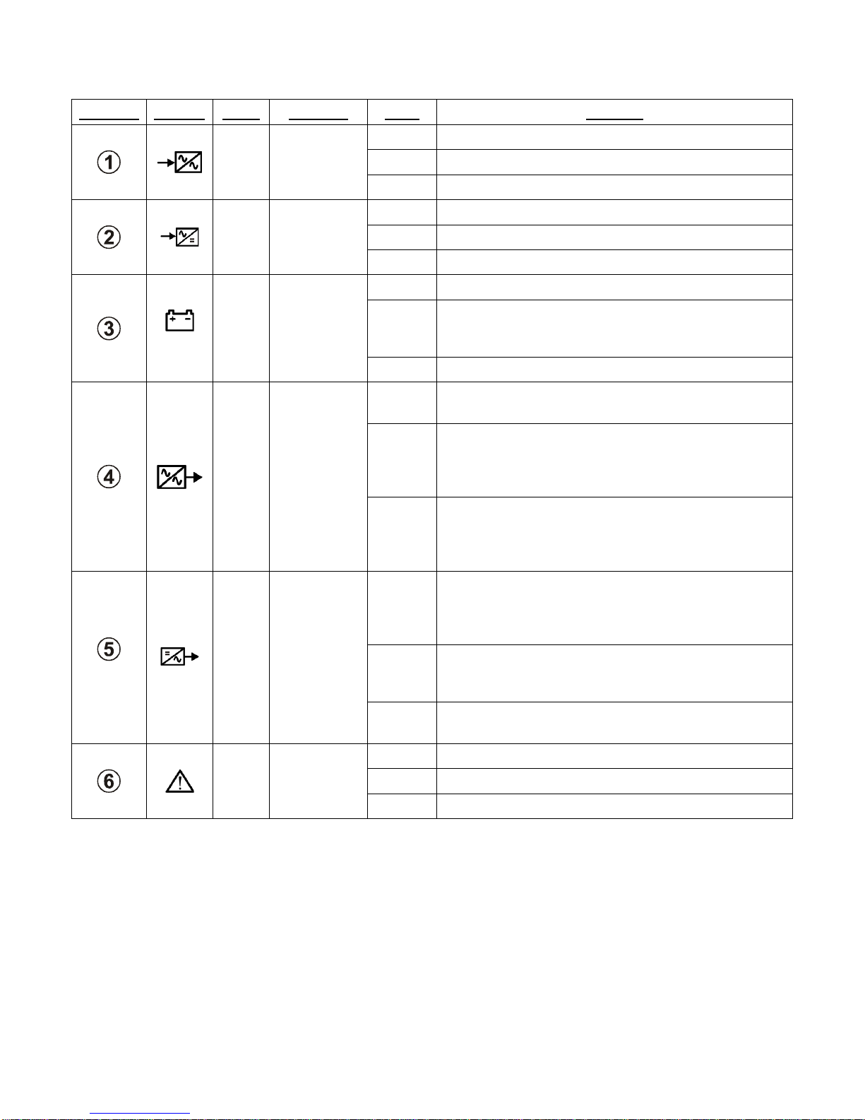
4.2.1 Diagram Items Shapes
Active
Inactive
Meaning
Key Off/ON
Icon
Meaning
Input converter
Output inverter
4.2.2 Keys Numbers and Icons
Battery
Manual bypass line switch
Bypass line input switch
Battery switch
Output switch
Main line input switch
Output load (40%VA or 0%VA)
Battery(70%Ah or 0%Ah)
Table 5 - Diagram Items Shapes
Information or n. 1
Measures or n. 2
Commands or n. 3
History or n. 4
Buzzer OFF/ON or n. 5
Display date/hours or. n. 6
Decrease value or sub menu or n. 7
Increase value or previous menu or n. 8
Table 6 - Keys Numbers and Icons
Page | 30
Page 41

4.3 Basic menu (text lines area)
If no commands have been inserted, the first text line shows messages to inform about status of
operation.
In each operating condition, the display returns to the "basic menu" after two minutes from the
last command. The basic menu shows the signal messages relating to the current operating
state
4.3.1 The First Line of the Basic Menu
When there are no alarms present the first text line of the main menu shows a fixed message,
“NORMAL OPERATION”
When some alarms are present, the first text line of the main menu shows each active ALARM message,
“ALARM MESSAGES”, one at a time for a few seconds:
Page | 31
Page 42
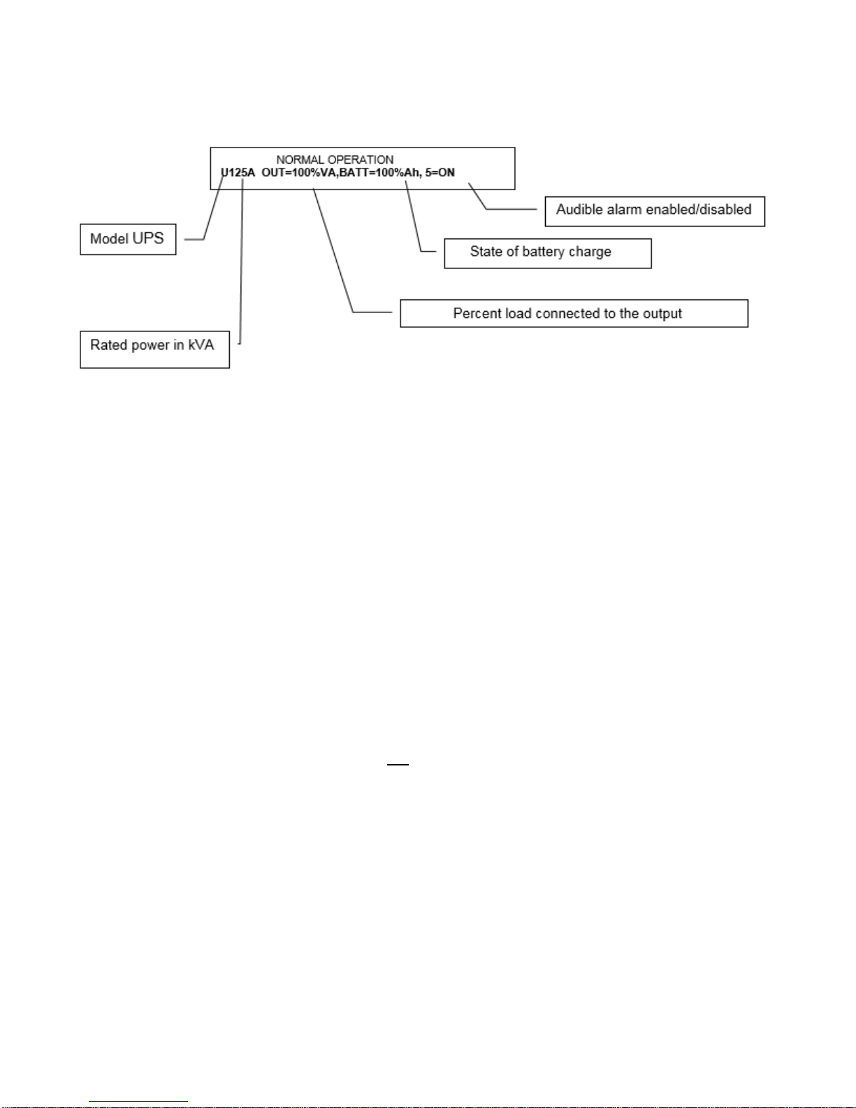
4.3.2 The Second Line of the Basic Menu
The second line displays the main operating values about system, output load, battery, buzzer and alarm
message number
• U125A indicates an UPS model with 125kVA rated power, operating with 60Hz output frequency.
o When the unit is set for the parallel operation the letter “P” is added (U125A P). The letter
“P” became lower case “p” when the unit operate as slave.
• 100%VA provided in the example is obtained from the measurement of the output current.
o The number indicates the output current with the value relating to the absolute rated value
and the value indicated is the greater of the effective current and the peak current.
• BATT= 100%Ah: example of the current state of the percentage of battery recharge.
o The value 100%Ah is obtained from the measurement of the charge current and the time
taken to recharge.
o The number indicates the recharge value as a percentage according to the capacity of the
battery connected and to the quantity of charge used during battery operation.
o The system automatically remains in rapid charging for all the time needed to supply the
battery with the quantity of charge lost during the discharge.
• %Ah changes to "min." (minutes) during operation in the event of a mains failure or when the
battery is discharging.
o The numeric value refers to the remaining minutes of operation, calculated according to
the current supplied by the battery and to the state of charge of the battery.
o The backup time shown is calculated according to the measurement of the discharge
current present at that time, the stored value relating to the capacity of the battery
connected and the stored value relating to the percentage of recharge prior to discharge.
The backup time shown should not be considered indicative due to the many different
factors affecting it. If considerable differences are noted between the expected value and
the actual time of a discharge with constant load, the stored data relating to the battery
must be checked, as must the state of the battery.
• 5=ON: example of the message showing whether or not the audible alarm is enabled; if disabled,
the message changes to 5=OFF.
Page | 32
Page 43

4.4 Language setting menu (keys 1, 1)
o Italian,
o Swedish,
o Polish,
o Portuguese.
From the keys menu, press 1 twice to access the languages menu.
The following languages are available:
o English,
o French,
o German,
o Spanish,
o Dutch,
o Hungarian,
o Turkish,
o Czech,
o Russian,
o Romanian and
The system will show all subsequent messages using the language chosen. The selected language
remains stored even after the shutdown and restart of the system. The current language can only be
changed by accessing the LANGUAGES menu.
Use keys 1 and 8 to return to the basic menu.
Page | 33
Page 44

4.5 Measurements menus (key 2)
IN
Out
Batt
Batt Out
The measurements with two line displayed, are selected from the basic menu by pressing key 2
IN
• IN=100,100,100%V, 60.2Hz Measurement of the three voltages, neutral phase and input frequency.
The voltage is indicated as a percentage of the rated voltage; for example 100% is equivalent to
277V.
• 101,101,101%A Measurement of the three input currents. The input currents are expressed as a
percentage of the rated value.
• BY=277,277,277Vln(480V) Measurement of the three input phase voltages of the bypass line, with
the concatenated voltage (the average of the three values) in brackets.
• 60.1Hz Frequency of the bypass line
Out
• OUT=230,230,230Vln Measurement of the three output phase voltages of the UPS, with the
concatenated value in brackets.
• 100,100,100%A Measurement of the three output currents. The output currents are expressed as a
percentage of the rated value.
• 100,100,100%W Measurement of the active output power. The power is expressed as a percentage
of the rated power.
• 60.1Hz Output frequency.
• 147,147,147%Ap Measurement of the three peak currents as a percentage relating to the three
output phases during operation from inverter. During operation from bypass, the message OUT
changes to BY.
Page | 34
Page 45

Batt
• BATT=xxxV Battery voltage value;
• +0.0A Battery current, positive with Battery discharging, negative with battery charging;
• i=230,230,230Vln Inverter output voltage;
• yyyVdc Input inverter DC voltage
• Ts=28, Tr=50, Ti=49, Tb=25; Temperature of the system, and of the rectifier and inverter
modules, Tb is present only if the external temperature the sensor is installed.
Batt Out
• OUT=10000h Hours of normal operation
• BATT=10000sec Time spent in operation from battery
• nBATT = 1000 Number of times the battery has discharged
• n0%Ah = 100 Number of times the battery has discharged fully
• 2007-01-01 Data stored on first start-up of the UPS. These are HISTORY data, and remain
stored even when the device is switched off and may not be reset.
Page | 35
Page 46
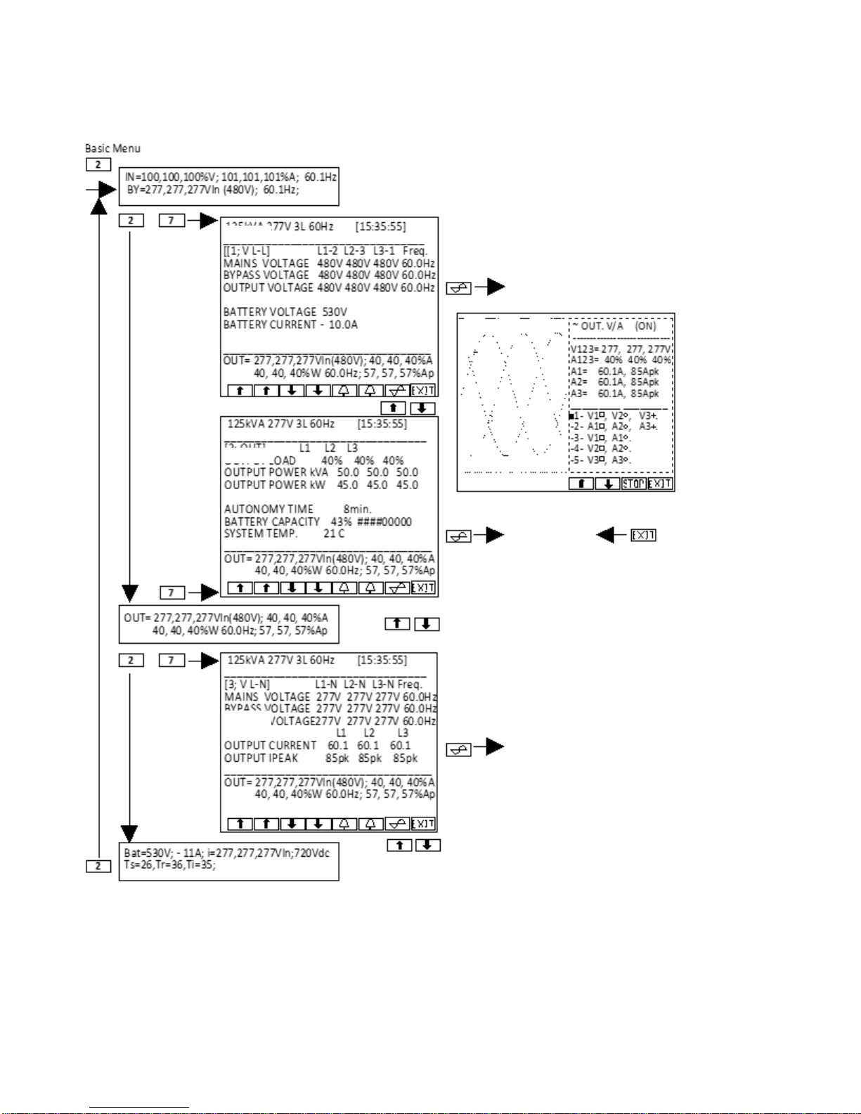
4.6 Full page Measurements and output waveforms (key 2, 7)
The full page measurements and output voltage and current waveform are selected by pressing key 7
from the two line measurement menu.
Page | 36
Page 47
4.7 Controls Menu (key 3)
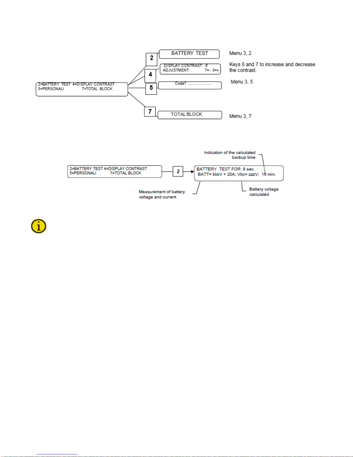
4.7.1 Battery Test (Keys 3, 2)
This activates the cycle to check the state of the battery, which lasts 8 seconds.
Press key 8 to interrupt the test and return to the basic menu before this time has elapsed.
The battery test cycle lowers the rectifier output voltage so that the battery can be evaluated with the
load even when the input voltage is present. The rectifier output voltage is only lowered if the bypass line
voltage is present, in order to avoid any disruption to the output load without the support of the bypass.
The battery test cycle can be activated:
• Manually;
• Automatically every 60 sec. after each failed test (for three times), or each time the system is
restarted;
• Automatically every 24 hours from system start-up;
• Automatically in invisible mode during operation without mains power supply.
At the end of each test, the alarm is activated if the voltage measured is lower than the calculated
voltage; the charge value stored and the backup time indicated are subsequently halved. A new test is
performed 60 sec. after activation of the alarm and if the result is negative the alarm is activated once
again for another 60 sec.
The alarms continue to halve the charge value stored until the calculated battery voltage is less than the
voltage actually measured. The battery control system produces an alarm each time the battery is seen
to have less than half of the expected charge.
• If this alarm is on PERMANENT, it indicates that the battery capacity is low, the battery circuit is
interrupted, the battery disconnect has remained open or one of the protection device fuses has
been triggered.
• If this alarm is on TEMPORARY, it indicates a reduction in the capacity of the battery; the more
frequent the alarm, the more serious the problem.
Page | 37
Page 48

Disabling the BATTERY TEST :
1. Press keys 3, 5: “CUSTOMIZ IN G”,
2. Insert code 323232, with battery test disabled the code o=02 will be shown in the basic menu of
the display.
3. To reactivate the test, insert code 323232 again.
4.7.2 Customizing
The "CUSTOMIZING" menu is accessed by means of key 5 from the COMMANDS menu; an
intermediate menu will then be displayed in which a CODE has to be entered.
Access by CODE ensures that unauthorized persons cannot modify the operating parameters
of the equipment.
The use of the codes to modify the operation of the equipment (such as the frequency converter,
stabilizer, rectifier start-up delay, etc.) is the prerogative of the service personnel.
The activated codes may be displayed (if present) with the following sequence of keys from the basic
menu:
1. 7 + 4 then by
2. Scrolling through the alarms with keys 7 and 8.
3. The following message will be displayed
Page | 38
Page 49
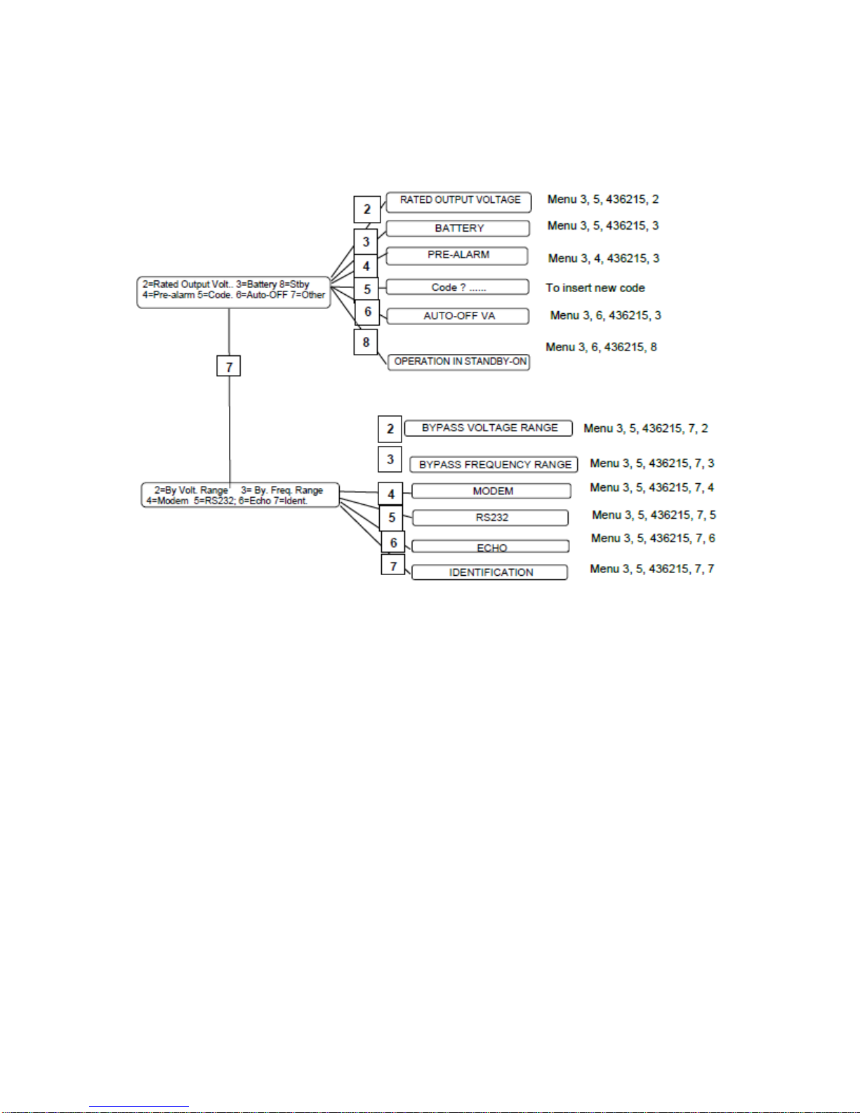
4.7.2.1 Entering Customized Code
Keys menu 3, 5: CODE 436215
The code is no longer required for 2 minutes after it has previously been inserted.
The next menu can only be accessed by inserting the correct code, otherwise it returns to the basic
menu.
4.7.2.2 Rated Output Voltage
Press the following sequence of keys to access the menu:
1. 3
2. 5
3. 436215
4. 2
Keys 7 and 8 can be used to decrease or increase the rated output voltage.
The value displayed is the voltage between phase and neutral "Vln". The value set modifies the
operation of the inverter, during normal operation. The new output value voltage also changes the
reference value for the acceptable range of the voltage at the bypass line input.
Page | 39
Page 50

4.7.2.3 Battery
Press the following sequence of keys to access the menu:
1. 3
2. 5
3. 436215
4. 3
On initial installation the rated capacity value of the connected battery must be inserted; this value is
usually printed on the battery container.
It is important to insert the correct battery capacity value, since this value is used by the system
logic to calculate the backup time.
If not set otherwise, this value is assumed to be equal to the UPS power. E.g. at 100kVA the
value set by default is 100Ah
Battery type =
1. Default pre-set for normal batteries;
2. High intensity discharge batteries;
3. Open vase batteries.
4.7.2.4 Cyclical Battery Recharging
1. Select type 1 or 2 and then press key 4 to display the pre-set voltage values:
2. Select type 0 and then press key 4 to modify the voltage values reset by keys 3,4 and 7,8.
4.7.2.5 Two-Level Charging
This type of recharging is effected with two current levels (EN 50272-2); the first phase comprises rapid
charging (U1) with limit ed current, while in the second phase charging is with float voltage (U2).
This type of recharging may be configured on site and is mainly used for special type batteries
such as open vase and NiCd .
Page | 40
Page 51
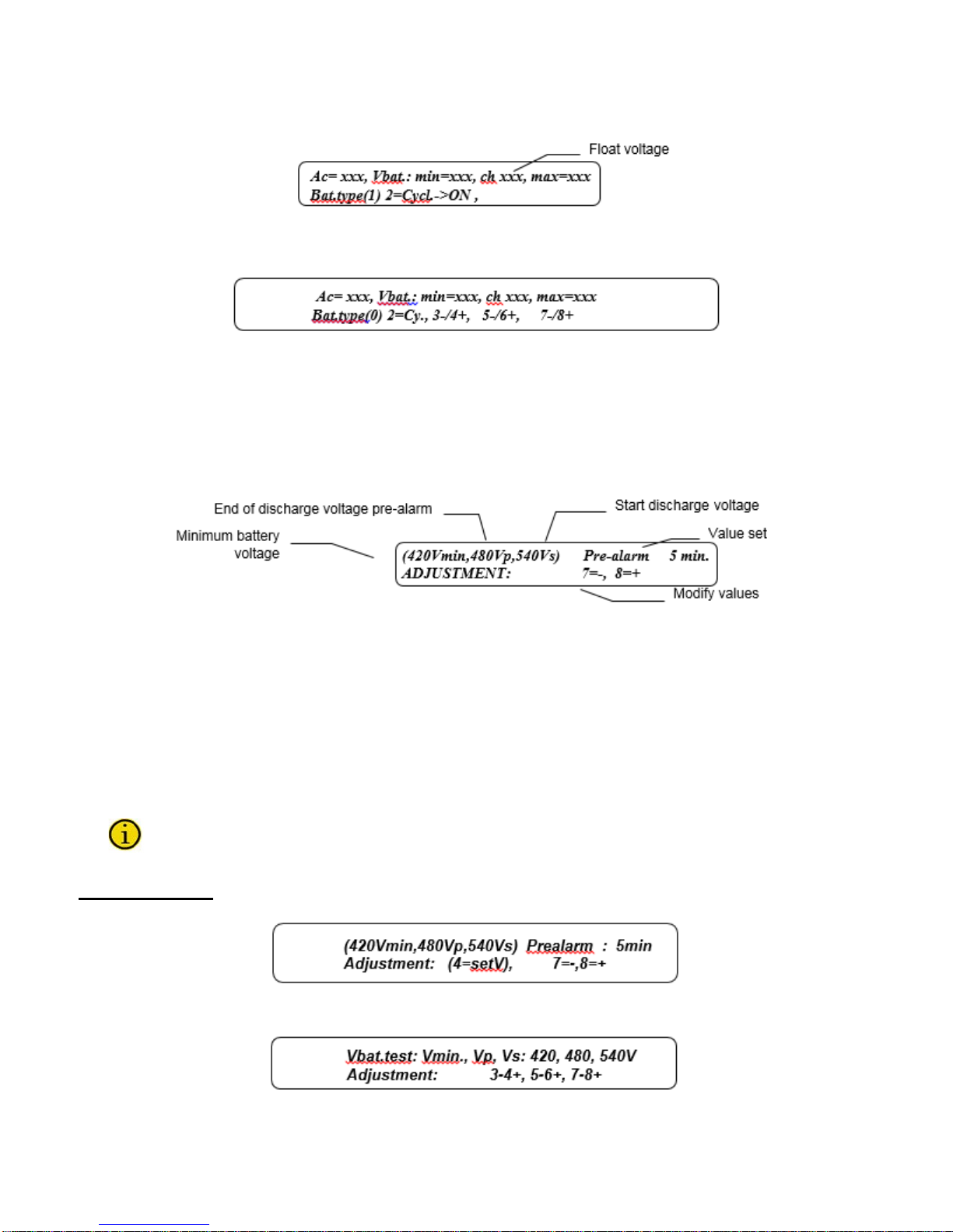
1. For batteries of type 1, 2 or 3, press key 2 from menu to change from cyclical charge to charging
at two levels
2. For batteries of type 0, press key 2 from menu to change from cyclical charge to charging at
two levels
3. Use keys 3,4; 5,6 and 7,8 to set the values
4.7.2.6 Pre-Alarm
Press the following sequence of keys to access the menu:
1. 3
2. 5
3. 436215
4. 4
Press key 1 to exit the menu.
The menu above will appear with batteries of type 1, 2 or 3.
• Voltage values Vmin, Vp and Vs are not fixed values but are a function of the battery discharge
current, [Vp= Vmin+5V+10*(battery current [A]/battery capacity [Ah]).
• Keys 7 and 8 can be used to decrease or increase the time to activate the pre-alarm before the
system blocks due to end of battery discharge. Variations in the field of 1 minute are possible
from 2 to 254 minutes.
• The pre-alarm signal is activated when the remaining calculated time is lower than the pre-alarm
value set or when the battery voltage is lower than the pre-alarm voltage value Vp.
A wide safety margin must be provided for the use of the pre-alarm function, since the
expected backup time may not provide for increases in the output load power, and may not
make allowance for sudden, unexpected battery defects.
Type “0” Battery
With the battery set to type 0, the following menu is displayed:
When key 4 is pressed, the program proposes the setting of the three voltage values.
Page | 41
Page 52

disharge time
Battery terminal voltage (V)
100%
90%
9,6V
Vmin*
Vs=12,2 V
Vp=11,2 V
1
3
2
With the three factory preset voltage values, the display panel may indicate an incorrect backup
time during discharge.
Battery type “0” setting
The three values to be set are linked to the battery discharge regime (relationship between discharge
current / battery capacity in Ah).
Example: for a 100Ah battery with a discharge current of 100A, the regime is 1.
The three values, Vs, Vmin and Vp, are obtained from the discharge characteristic curve, supplied from
manufacturer, relating to the battery discharge regime 1C has been determined:
• Vs Start of discharge voltage (1), intersection with the x-axis (battery terminal axis), [the value
must be multiply for 40, number of batteries]
• Vmin Minimum voltage value (end discharge battery ), point of intersection with the dashed curve
(if this value is lower than Vmin* set up Vmin=Vmin* (2).[the value must be multiply for 40,
number of batteries]
• Vp Battery voltage with discharge at 90% of the total time (3).
Page | 42
Page 53

4.7.2.7 Auto-Off "VA"
Press the following sequence of keys to access the menu:
1. 3
2. 5
3. 436215
4. 6
Press key 1 to exit the menu.
Keys 7 and 8 can be used to decrease or increase the percentage threshold of the output load for the
AUTO-OFF function and switching the system to the bypass line; variations of 1% are possible in the
field from 0 to 99% of the rated output load.
• For shutdown with mains present, when the output power reaches < of the value set, the battery
charge value must be > 60%.Once this value is reached the system is deactivated.
• For shutdown with power output < value set, it must be verified that the battery capacity value is >
60%. Shutdown is not immediate, but is delayed by the time set as the end of battery discharge
pre-alarm (standard value 5 minutes); in this phase the “end of discharge pre-alarm” contact of
the remote alarms card is switched, after this time the output is switched to the bypass line if this
voltage is present and the voltage also remains present at the output.
The load remains switched to the bypass line while the output power remains lower than the "AUTOOFF" value, then the system waits for an increase in the load before effecting the automatic return to
normal operation;
The “AUTO-OFF” function may be used to shut down the system during operation from battery, simply by
shutting down the output load. In normal operation, the “AUTO-OFF” function may be used to reset
consumption since the power circuits are deactivated, the battery remains isolated and only the control
circuits, with consumption equivalent to a light bulb, remain active.
4.7.2.8 Auto-Off Timer
Press the following sequence of keys to access the menu:
1. 3
2. 5
3. 436215
4. 6
5. 5
The keys have the following functions:
• 6 to modify the value Ton
• 5 to modify the value Toff.
Toff and Ton are time values used by the system to affect an automatic daily shutdown and restart cycle.
The timer cycle is inhibited when Toff = Ton.
When the internal clock reaches the time Toff, if the mains voltage is present and the percentage of
recharge is less than 60%, only the following is displayed:
Page | 43
Press key 1 to exit the menu.
Page 54
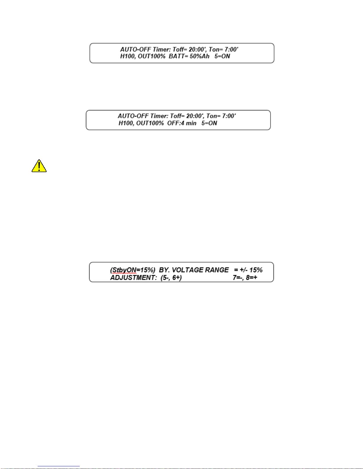
The system waits until the battery recharge exceeds the value of 60% before deactivating.
When the internal clock reaches the time Toff, if the mains voltage is present and the percentage of
recharge is greater than 60%, or the mains voltage is not present and operation is from battery, the
following is displayed:
The "end of discharge pre-alarm" contact for remote alarms is also switched.
In this case the system remains active for the next 4 minutes, after which the system switches onto the
bypass line and then deactivates.
There is no output voltage after deactivation.
The interval between the start of the alarm and deactivation is equal to the interval selected as PREALARM. When the internal clock reaches the time Ton, if the mains voltage is present, the system
automatically reactivates and returns to normal operation.
4.7.2.9 Bypass Voltage Range Adjustment
Press the following sequence of keys to access the menu:
1. 3
2. 5
3. 436215
4. 7
5. 2
Press key 1 to exit the menu.
Keys 7 and 8 can be used to decrease or increase the value, as a percentage, of the acceptable range
for the voltage at the bypass line input, with respect to the rated output value.
Keys 5 and 6 can be used to reduce or increase the percentage of the acceptable range of the bypass
voltage in STBY ON mode.
4.7.2.10 Bypass Frequency Range Adjustment
Press the following sequence of keys to access the menu:
1. 3
2. 5
3. 436215
4. 7
5. 3
Press any key other than 7 or 8 to exit the menu. Keys 7 and 8 can be used to decrease or increase the
value, as a percentage, of the acceptable range for the frequency at the bypass line input. The choice is
between the values +/- 1%, and +/- 5% relative to th e rated system value of 60 Hz.
Page | 44
Page 55

4.7.2.11 MODEM Set-up
Press the following sequence of keys to access the menu:
1. 3
2. 5
3. 436215
4. 7
5. 4
Press key 1 to exit the menu.
Keys 7 and 8 can be used to decrease or increase the control value for management of the modem. The
choice is between the values of 0 to 5. The initial value is 0.
• 0 Modem connected to the RS232 port is deactivated. Terminal 20 of the RS232 connector
assumes a low level (-12V) (DTR signal deactivated).
Configuration MODEM=0 is essential when the modem is not used and the RS232
connector is used for connection to the remote panel.
• 1 Signal DT R is activated (terminal 20 at +12V), the modem is enabled to reply (it should be
remembered that a remote panel connected to the RS232 connector in place o f the modem
remains off).
• 2 Signal DTR is activated, the modem is ready to reply and for automatic calls.
o After an "internal fault" alarm has been on for 30 seconds, the system automatically dials
the stored "DIAL" number. When it receives the modem’s receiving reply it sends a
message made up of the UPS acronym, the stored "SEND" number, a copy of the text
shown on the display, the alarm code and the date and time of transmission.
For correct operation, use a modem that has already been configured to recognize
"HAYES" type commands and that is able to dial the telephone number using pulses or
tones as required by the telephone line that is to be used.
o If the telephone line is engaged or the remote modem does not reply, the system tries to
call again every 5 minutes until it manages to connect, provided that the alarm condition is
still present.
• 3 Same as 2 with automatic call when any alarm is verified.
• 4 Same as 2 with automatic call only for alarm 10, and with sending of message only after the
reply from the remote modem has been acknowledged by the reception of the character "}". This
mode ensures that the receiving computer does not lose any messages.
• 5 Same as 4 with automatic call when any alarm is verified.
Page | 45
Page 56

4.7.2.12 "Dial /Send" MODEM
Press the following sequence of keys to access the menu:
1. 3
2. 5
3. 436215
4. 7
5. 4
6. 5 (6)
Press key 1 to exit the menu.
Keys 7 and 8 can be used to decrease or increase the figure on which the cursor is positioned.
The cursor is moved by means of keys 2 and 3, and is indicated initially by the character '_'.
Each number may assume values from 0 to 9, the symbol / indicates that the corresponding figure is
disabled.
A correct "dial" number must start with a figure from 0 to 9, the setting /6543210 is ignored.
Select menu 35746 or press key 6 when menu 35745 is active to set the "send” number.
4.7.2.13 RS232
Press the following sequence of keys to access the menu:
1. 3
2. 5
3. 436215
4. 7
5. 5
Press key 1 to exit the menu. Keys 7 and 8 for RS232-1 (3 and 4 for RS232-2) can be used to decrease
or increase the baud value for the transmission speed.
• 1200
• 2400
• 4800
• 9600
4.7.2.14 ECHO
Press the following sequence of keys to access the menu:
1. 3
2. 5
3. 436215
4. 7
5. 6
Press key 1 to exit the menu. Keys 7 and 8 can be used to decrease or increase the number used to
enable the "ECHO" function. The number may vary from 0 to 1 to disable or enable the function. When
the function is enabled the system automatically sends a copy message of the display with the addition
of the code "a=........" and the current date and time to the RS232 output.
The message is sent for each variation in the state of the alarms (that is, any change in code a=.......).
Page | 46
Page 57
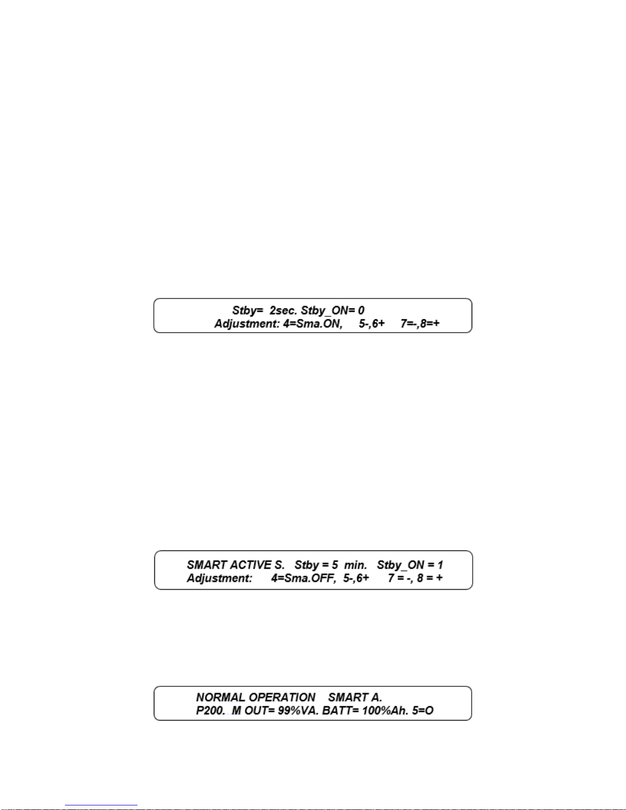
4.7.2.15 IDENT
Press the following sequence of keys to access the menu:
1. 3
2. 5
3. 436215
4. 7
5. 7
Press key 1 to exit the menu. Keys 7 and 8 can be used to decrease or increase the number used for the
identification of a single unit in systems with several UPS connected to a single RS232 serial line. The
basic number is 0 and may be changed between values from 0 to 7.
4.7.2.16 Operation in Standby-On
Press the following sequence of keys to access the menu:
1. 3
2. 5
3. 436215
4. 8
Press key 1 to exit the menu.
Press key 8 Stby=1 to change the UPS from ON-LINE mode to STANDBY-ON mode.
Press key7 to change the UPS from STANDBY-ON mode to ON-LINE mode.
The switch onto the bypass line may be immediate when “Stby = 0 min.” or delayed by means of keys 5
and 6.
The backup line must be available for the time set within the acceptance field before the switchover can
take place. The setting remains stored even during a shutdown due to a power failure. For a description
of the operation see the Section 3.4 Operating Modes
4.7.2.17 Smart Active Operation
Press the following sequence of keys to access the menu:
1. 3
2. 5
3. 436215
4. 8
5. 4
When the Smart Active function is activated via key 4, Stby_ON goes to 1. The setting remains stored
even during a shutdown due to a power failure. There is a delay of 5 minutes before transfer to Smart
Active mode. For a description of the operation see the Section 3.4 Operating Modes.
When the code is inserted the basic menu becomes:
Page | 47
Press key 1 to exit the menu.
Page 58

4.7.2.18 Inverter-Off/Bypass
Press the following sequence of keys to access the menu:
4. 3
5. 6
Exit the menu by pressing key 8 or any other key with a sequence other than the one described here.
Pressing keys 4, 7, 2, 6, 3 in succession as shown on the display activates the command for bypass with
shutdown of the inverter. The command is executed after a few seconds’ delay to allow for cancellation.
When this command is active, the following alarm is shown on the display:
"BYPASS COMMAND ACTIVE; 8=DEACTIV. ".
To return to normal operation, including after system shutdown, the command has to be cancelled by
pressing key 8, or by sending the key code through the RS232.
NOTE To mask the command code 47263, insert code 436213 on the panel from the
PERSONALIZATIONS menu (keys 3, 5). Repeat the operation to display the code again.
4.7.2.19 Total Block
Press the following sequence of keys to access the menu:
1. 3
2. 7
Exit the menu by pressing key 8 or any other key with a sequence other than the one described here.
Pressing keys 4, 7, 2, 6, 3 in succession as shown on the display activates the command for TOTAL
BLOCK of the system. When this command is active, the display shows the alarm
BLOCK COMMAND ACTIVE; 8=DEACTIV.
The command is executed after a few seconds’ delay to allow for cancellation. This command is useful
to achieve full deactivation in an emergency, operating remotely via the RS232 line. To reactivate the
UPS, press button 8.
To mask the command code 47263, insert code 436213 on the panel from the
PERSONALIZATIONS menu (keys 3,5). Repeat the operation to display the code.
4.7.3 "Recorder": Recorded Events (key 4)
Press the following sequence of keys to access the menu: 4
• Key 1: Return to the basic menu by
• Key 2 activates the submenu "RECORDED VOLTAGES MEASUREMENTS".
• Keys 3, 4 and 5 keep their normal functions.
• Key 6 activates submenu 4, 6 " RECORDED CODES" and allows the exchange of stored alarm
message with the display of the corresponding status codes at the time of the stored event, and
vice versa. The status codes allow a more in-depth analysis by the trained personnel.
Page | 48
Page 59

4.7.3.1 Recorded Voltag es Measurements
Press the following sequence of keys to access the menu:
1. 4
2. 2
3. 2
4. 2
The "RECORDED VOLTAGES MEASUREMENTS" menu is accessed via key 2 (press 2 again to access
the other measurement menus from menu 4 "RECORDED EVENTS" or menu 4, 6 "RECORDED
CODES" only. Press key 1 to return to the basic menu immediately.
In the example, n 35 (flashing) indicate that the measurements shown refer to the state relating to
recorded event number 35. The meaning of the measurements is the same as those in menu 2.
4.7.3.2 Recorded Codes
Press the following sequence of keys to access the menu:
1. 4
2. 6
The "RECORDED CODES" menu is accessed with key 6 from menu 4 "RECORDED EVENTS" and
menus 4, 2; 4, 2, 2; 4,2,2,2 that is, the recorded measurement menus. Return to the basic menu by
means of key 1.
Apart from key 6, the other keys have the same functions as those described for menu 4, and the
messages on the lower line also remain the same.
The upper line: s=FFFF c=FFFF b=FFFF r=FFFF-FF i=FFFF-FF, shows the internal codes recorded at
the time of the event.
Use key 6 to return to menu 4 while keeping the current event; you can then switch several times from
the description of the event with the "stored alarm message" to the one with the internal codes.
4.7.3.3 Recorded Value on Full Page
The "RECORDED value on full page” menu is accessed with key 4 from menu 4.
On this page, when the “stop” key is not cross marked, are shown all present measurements and internal
codes, and the past measurements when the “stop” key is marked.
When the “STOP” key is cross marked it is possible to look to the other past value recorded by arrow
keys.
Page | 49
Page 60
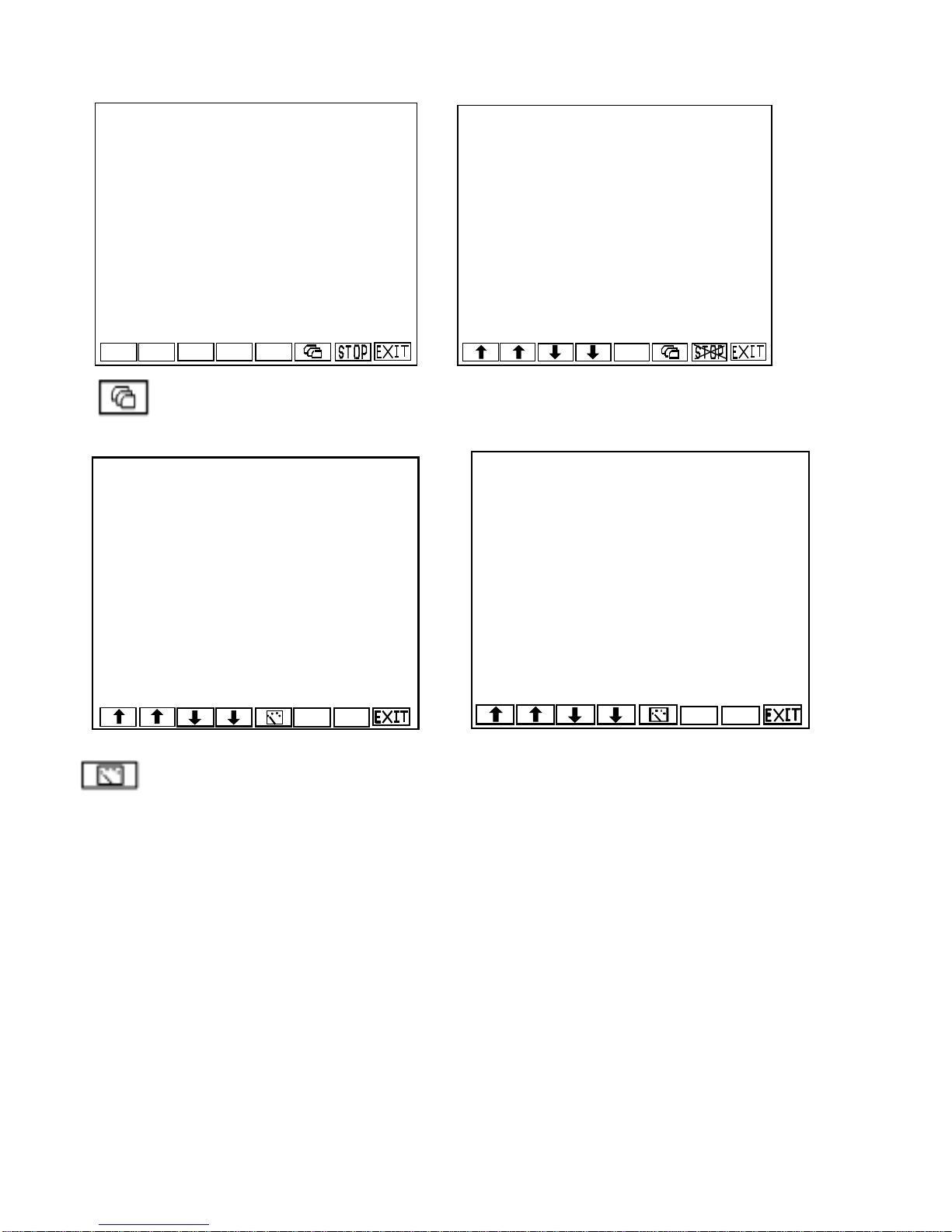
NORMAL OPERATION
a=0000-0000 2013- 1-24/15:35: 120;
---------------------------------------------------------s=8000 c=0000 b=0000 r=0000-00 i=0000-00
====================================
IN=100,100,100%V; 45, 45, 45%A; 60.1Hz
---------------------------------------------------------OUT= 230,230,230ln(400V); 40, 40, 40%A
40, 40, 40%W 60.0Hz; 57, 57, 57%Ap
---------------------------------------------------------Bat=XXXV; - 11A; i=230,230,230Vln;XXXVdc
Ts=26,Tr=36,Ti=35;
NORMAL OPERATION
a=0000-0000 2011- 1-24/13:35: 0;n120
------------------------------------------------------
PREALARM, LOW BATTERY VOLTAGE
a=1C00-0000 2011- 1-24/10: 1: 3;n119
----------------------------------------------------- MAIN LINE VOLTAGE FAIL or SWIN OFF
a=1800-0000 2011- 1-24/10:05: 1;n118
----------------------------------------------------- NORMAL OPERATION
a=0000-0000 2011- 1-24/10:01:18;n117
---------------------------------------------------------MAIN LINE VOLTAGE FAIL or SWIN OFF
a=1800-0000 2011- 1-24/09:40: 1;n116
6
s=8000 c=0000 b=0000 r=0000-08 i=0000-00
a=0000-0000 2013- 1-24/13:35: 0;n120
-----------------------------------------------------------s=8000 c=0000 b=3C20 r=0000-08 i=0000-00
a=0400-0000 2013- 1-24/13: 5: 5;n119
-----------------------------------------------------------s=8000 c=0000 b=0000 r=F881-00 i=0000-00
a=1C00-0000 2013- 1-24/13: 1: 3;n118
-----------------------------------------------------------s=8000 c=0000 b=0000 r=F881-00 i=0000-00
a=1800-0000 2013- 1-24/12: 1: 1;n117
-----------------------------------------------------------s=8000 c=0000 b=0000 r=0000-08 i=0000-00
a=0000-0000 2013- 1-24/11: 4:18;n116
6
This key switch to the page showing the message and codes of 4 past events and it is
possible to look to the other past events by arrow keys.
This key switch to page with all codes and measurements displayed of 1 event. The key “6”
switch from code with message line to full lines code.
4.7.4 Disabling the Audible Alarm (key 5)
Press the following sequence of keys to access the menu: 5
During operation from the basic menu, the operator can permanently disable or re-enable the audible
alarm (buzzer) by pressing key 5. "5=ON" is shown in the basic menu when the audible alarm is enabled
and "5=OFF" when the audible alarm is disabled. Key 5 in other menus may only be used to disable the
sound, when no other functions are envisaged for this key. The command is stored even during a
shutdown due to a power failure.
Page | 50
Page 61
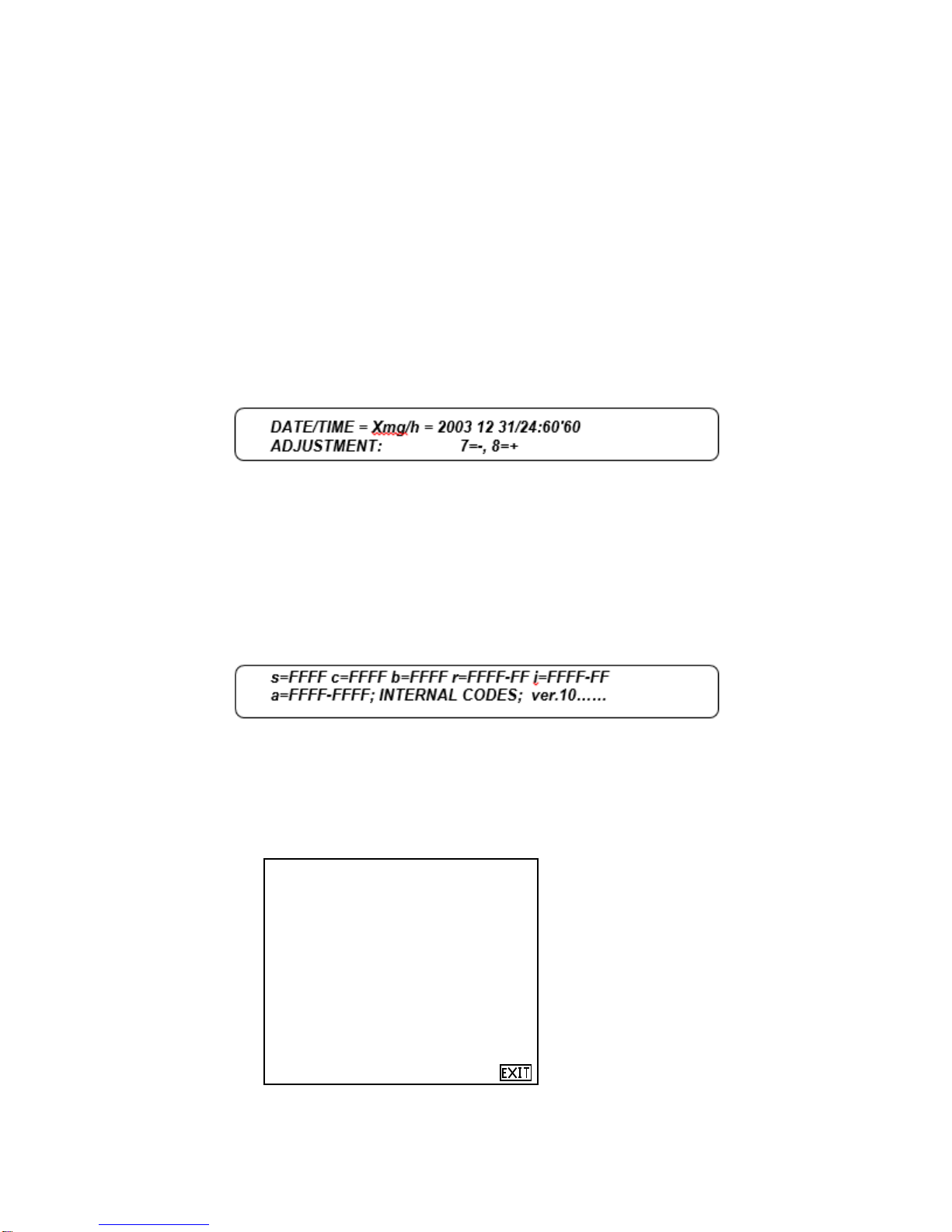
4.7.5"Clock": Date/Time (key 6)
125kVA 277V 3L 60Hz [15:35:55]
_________________________________
System: Ver.= 28, rev= 1, ck=A404
Panel: Ver.= 01, rev= 1, ck=B235
DSP: Ver.=3333, rev= 0, ck=1ABC
Serial N.= ML36AP183410001
Dial Tel.= 0201010101010
_________________________________
NORMAL OPERATION
U125AA OUT= 40%VA, Batt= 35% 5=0N
Press the following sequence of keys to access the menu: 6
The "DATE/TIME" menu is accessed via key 6 from the basic menu.
The display shows the current contents of the internal calendar and clock with the following format:
DATE/TIME = ymd/h = years, months, days / hours, minutes, seconds.
The contents can be modified via the menu by inserting the personalization code 436215. This code
remains active for 2 minutes after it has been inserted.
The next menu can only be accessed by inserting the correct code, otherwise the system returns to the
basic menu.
Press keys
1. 2
2. 3
3. 4
4. 5 or 6 to select which value to change.
In this case the year’s value is to be changed; the flashing symbol X superimposed over the letter shows
which field has been selected. Press keys 7 or 8 to decrease or increase the selected value by one unit;
press any one of the other keys to exit the menu.
4.7.6 "Arrow Down": Internal Codes, Firmware Ver.(key 7)
Press the following sequence of keys to access the menu: 7
The "INTERNAL CODES" menu is accessed from the basic menu via key 7. The codes represented
provide information on the operating status of the UPS and about system firmware version. This
information is used by the service personnel.
Pushing more key 7 it is shown the page with information about other firmware version, serial number
and service telephone number.
Page | 51
Page 62

5. UL924 Emergency Lighting Systems
CSB
FIAMM
C & D
HRL 12540W
12FLX540
UPS12-540MR
FLU-P-924-58
58.5kW
FLU-065
2
FLU-P-924-72
72kW
FLU-080
3
FLU-P-924-90
90kW
FLU-100
3
FLU-P-924-112
112.5kW
FLU-125
4
FLU-P-924-144
144kW
FLU-160
5
FLU-P-T-924-144
144kW
FLU-160-T
5
FLU-P-924-180
180kW
FLU-200
6
FLU-P-T-924-180
180kW
FLU-200-T
6
FLU-P-924-225
225kW
FLU-250
8
FLU-P-T-924-225
225kW
FLU-250-T
8
The Staco FirstLine P can be used as part of an approved UL924 Emergency Lighting system.
Table 7 – Battery Models approved for UL924
Table 8 – UL924 Approved Systems
Staco UL924
Model #
kW
Staco UPS
Model #
# of Strings of
540W batteries
Page | 52
Page 63

6. Maintenance
The Uninterruptible Power Supply is designed and produced to last a long time, even in the most
severe service conditions. It should be remembered however that this is electronic power
equipment, which requires periodic maintenance. Moreover, some components have a limited
lifespan and as such must be periodically checked and replaced should conditions so dictate: in
particular the batteries, the fans and in some cases the electrolytic capacitors. It is therefore
recommended to implement a preventive maintenance program which should be entrusted to
specialized personnel authorized by the manufacturer.
Our Technical Support Team will be happy to recommend the various personalized options for
preventive maintenance.
6.1 Periodic Maintenance (to be carried out by trained personnel and with doors closed)
The following operations (which must be done with the doors closed) should be carried out periodically
(e.g. once a month, or more frequently in particularly difficult environmental conditions):
• Ensure that the air intake slots (located on the front door and at the back of the cabinet) and the
output grilles located on the top of the cabinet are clean;
• Ensure that the UPS is working properly (the message “NORMAL OPERATION” will appear on
the display panel). If an alarm message is displayed, check the meaning in the manual before
contacting the technical support service;
• Perform a battery test via the display panel.
6.2 Maintenance Inside the UPS (factory authorized personnel only)
Danger
Maintenance inside the UPS may only be carried out by trained personnel. The UPS is
designed to power the load when it is disconnected from the mains power supply.
High voltage is present inside the UPS even when the mains power supply and the
battery have been disconnected.
After disconnecting the input utility and the battery source, trained service personnel must wait
at least ten minutes for the capacitors to discharge before working on the inside of the UPS.
6.3 Ordinary Maintenance for Batteries (trained personnel only)
The system automatically controls the efficiency of the batteries every 24 hours, and sounds an alarm
when the efficiency is lower than that calculated, according to the stored capacity value.
The lifespan of the batteries is linked to the operating temperature and to the number of charge and
discharge cycles the battery has experienced.
The capacity is not constant, but increases after some charge and discharge cycles; it then remains
constant for several hundreds of cycles before decreasing permanently.
Preventive maintenance of the battery:
- Keep the operating temperature within the range of 20 - 25°C;
- Perf orm two or three discharge and charge cycles during the first month of use;
- Repeat t his operation every six months after the first month of use.
Danger
Maintenance inside the UPS may only be carried out by trained personnel.
Since the batteries are a source of energy, opening the battery circuit breaker/disconnect
does not eliminate the voltage inside the battery cabinet. DO NOT TRY TO ACCESS THE
INSIDE OF THE BATTERY CABINET. THERE ARE ALWAYS DANGEROUS VOLTAGES
FROM THE BATTERIES. If the batteries are thought to be faulty in any way, please contact
Staco technical support.
Page | 53
Page 64

Warning
Component
Recommend Replace in:
Fans
4-6 years
Batteries
4 years
AC Filter Capacitors
4-6 years
DC Filter Capacitors
4-6 years
If the batteries need to be replaced, this must be done by factory authorized personnel.
The replaced parts must be sent to a specialized company for disposal by means of
recycling. Batteries are classified by law as “toxic waste”.
6.4 Recommended Replacement Intervals
The Staco UPS has a long design life. Due to the characteristics of the part, not the design of the UPS,
certain components used in the design have a limited life, even with proper maintenance.
Service and maintenance work must be performed only by factory authorized personnel.
Staco recommends these limited-life components be periodically inspected and replaced before the
expected expiration of their life cycle. The recommended replacement schedule is an estimate only. The
life of these parts depends on site conditions such as ambient temperature, load profile, cleanliness of
environment and other factors. See Section 7.2 Environmental Requirements
Staco Recommends a Factory Authorized Preventative Maintenance review is schedule at least once a
year.
Table 9 - Recommended Replacement Intervals
The functional lifetime of batteries is significantly affected by the temperature at which they are stored
and operated. Ideally, batteries should be used in a 21º C (70º F) environment. For every 8.3º C (15º F)
increase in temperature, the life expectancy of a battery will be halved.
Exposure to temperatures in excess of 32º C (90º F) should be limited to no more than 30 days per year.
Under no circumstances should the battery be exposed to temperatures over 40º C (104º F) which can
lead to thermal runaway, a condition that damages the battery. Thermal runaway can cause batteries to
swell. If the battery cases burst, the hazardous contents may be exposed.
Maintaining proper ambient temperature usually requires installing the product in a temperature
controlled space. Equipment rooms without cooling systems do not generally maintain the proper
conditions for good battery life.
Page | 54
Page 65

7. Specifications
UPS Models
160 kVA
200 kVA
250 kVA
INPUT RECTIFIER
Rated Voltage
480Vac 3-phase
Rated Voltage Tolerance w/o Contrib. of Battery
@100% Load
Voltage Tolerance In Battery Mode or Load Depending
-40%, + 15%
Input Frequency Tolerance [Hz]
45 to 65
Power Factor at Rated Voltage (480 V) and Battery
Charge from 25% to 100% of the Load
≤ 3 at 100% Load
≤ 5 at 75% Load
≤ 8 at 25-50% Load
Rectifier Power Walk-In
from 0 to 30 seconds (configurable)
Rectifier Power Walk-In Delay Timer
from 0 to 120 seconds (configurable)
D.C. CIRCUIT
Number of Jars /Cells
40 / 240
Ripple Voltage with Recharged Battery [%]
Approx. 0
Max Recharge Current [A]
Full load
35
45
55
Load 90%
60
80
100
Load 80%
90
110
140
Load ≤ 70%
110
130
165
INVERTER
Active Power [kW]
144
180
225
Rated Power Reduction Factor (kVA/kW) for
PF =0.8/0.9 Capacitive
Rated Voltage
480Vac 3-phase + N
Rated Frequency [Hz]
60
Rated Voltage Adjustment
-0.05
Static Variation
± 1%
Dynamic Variation
± 5%
20ms;
Conforms to standard EN 62040-3, class 1
Non- linear load capability
Conform to standard IEC 62040-3 annex E
1% (typical),
2% (max)
Voltage Distortion with Non-Linear Load
< 3%
Frequency Stability
(Synchronized with the Bypass Mains )
± 2%
(adjustable from ± 1% to ± 6% from control panel)
Frequency Stability
(Not Synchronized with the Bypass Mains )
Frequency Slew Rate
1Hz/sec
Dissymmetry of the Phase Voltages with Balanced &
Unbalanced Load
Voltage Phase Shift with Balanced & Unbalanced Load
120 ± 1 °el
Overload
Three Phase
110% for 60min , 125% for 10min , 150% for 1min
Mono Phase
200% for 7 second
Short Circuit Current
Phase / Phase
180% for 1 second with current limiting
Phase / Neutral
300% for 1 second with current limiting
7.1 Electrical Specifications
-10%, +15%
>0.99
Current Harmonic Distortion [THDi]
(with Mains Distortion <1%)
Recovery Time within ± 1%
0.85/0.89
Voltage Distortion with Linear Load
Page | 55
± 0.05%
≤ 1%
Page 66

UPS Models
160 kVA
200 kVA
250 kVA
Inverter Efficiency [%]
95%
Normal Mode AC/AC Efficiency
93%
Normal Mode Heat Rejection [BTU/Hr]
36,860
46,072
57,676
Bypass
Rated Voltage
480Vac 3-phase + N
Rated Voltage Tolerance
± 15% (adjustable from ± 10% to ± 25%)
Rated Frequency
60Hz
Frequency Tolerance
± 2% (adjustable up to ± 6%)
Switching to Bypass with Synchronized Inverter
Approx 0ms
Switching to Bypass with Inverter out of Sync
20ms
Switching from Bypass to Inverter
from 2 to 5ms
Delay in Transfer to Inverter after Switching to Bypass
4 sec
Overload
110 % for 60 minutes,
150 % for 1 minute
Short Circuit Current
1 second
9
11
9
500 ms
10
12
10
200 ms
11
15
12
100 ms
12
16
13
10 ms
18
23
18
Rated Ambient Temperature (UPS)
32 - 104°F (0 - 40°C)
Maximum Temperature for 8 hours a day
104°F (40°C)
Average Temperature for 24 hours
95°F (35°C)
Recommended Battery Temperature
68 – 86°F (20 - 30°C)
Humidity
<95% (without condensing)
Up to 3280ft. (1000m) above sea level
13,123ft. (4000m)]
UPS: -4 to 158°F (-20 to 70°C)
Battery: -4 to 86°F (-20 to 30°C )
UPS models
Width (inches [mm])
39.4 [1000]
Width w/TCE (inches [mm])
55.1 [1400]
Depth (inches [mm])
33.5 [850]
Height (inches [mm])
75.02 [1905]
Weight (lbs [kg])
1984 [900]
2205 [1000]
2425 [1100]
Weight w/T CE (lbs [kg])
2326 [1055]
2546 [1155]
2767 [1255]
Ventilation
Forced
Noise at 1m from front
(0-100% load)[dBA]
UL Standard 1778 5th Edition; National Electrical Code (NFPA-
.ANSI C 62.41-1980; ISO9000
Short Circuit Withstand Rating
Without TCE
50 kArms @ 480 Vac
With TCE
18 kArms @ 480 Vac, max 50ms
7.2 Environmental Requirements
125 % for 10 minutes,
Maximum Operating Altitude
Storage Temperature
7.3 Mechanical Specif icat io ns
Applicable Standards
[derating of 1% each 328ft (100m) between 3280ft. (1000m) and
68
70);NEMA PE-1; CUL to CSA C22.2; ASME, ASA-C-39.1-1984;
FCC Part 15 Subpart J Class A; NEC; OSHA; IEEE587;
Page | 56
Page 67

7.4 Rated Currents
UPS
models
Nominal
Current
Maximum
Current
OCP
Current
OCP Device
rating
Bolt Size
(in.)
Phase and Neutral
Conductor
Ground
Wire
160 kVA
188A
212A
265A
300A
3/8
(2) 1/0AWG
4AWG
200 kVA
235A
265A
331A
350A
3/8
(2) 2/0AWG
4AWG
250 kVA
294A
331A
414A
450A
3/8
(2) 4/0AWG
4AWG
UPS
models
Nominal
Current
Maximum
Current
OCP
Current
OCP Device
rating
Bolt Size
(in)
Phase and Neutral
Conductor
Ground
Wire
160 kVA
188A
212A
265A
300A
3/8
(2) 1/0AWG
4AWG
200 kVA
235A
265A
331A
350A
3/8
(2) 2/0AWG
4AWG
250 kVA
294A
331A
414A
450A
3/8
(2) 4/0AWG
4AWG
UPS
models
Nominal
Current
OCP
Current
OCP Device
rating
Bolt Size
(in)
Phase and Neutral
Conductor
Ground
Wire
160 kVA
192A
240A
250A
3/8
(2) 1AWG
4AWG
200 kVA
241A
301A
350A
3/8
(2) 2/0AWG
4AWG
250 kVA
301A
376A
400A
3/8
(2) 3/0AWG
4AWG
UPS
models
Nominal
Current
Bolt Size
(in)
Phase and Neutral
Conductor
Ground
Wire
160 kVA
192A
3/8
(2) 1AWG
4AWG
200 kVA
241A
3/8
(2) 2/0AWG
4AWG
250 kVA
301A
3/8
(2) 3/0AWG
4AWG
Nominal
(@480Vdc)
160 kVA
316A
378A
400A
3/8
(2) 3/0AWG
4AWG
200 kVA
395A
473A
500A
3/8
(2) 250kcmil
4AWG
250 kVA
493A
591A
600A
3/8
(3) 3/0AWG
4AWG
To reduce the risk of fire, connect only to a circuit provided with branch circuit protection with
maximum current rating per the table, below, in accordance with the National Electrical Code,
ANSI/NFPA 70.
Use at least 75o C rated copper wire. Minimum wire size is based on full load ratings applied to
NEC Code Table 310-16. Code may require a larger AWG size than shown in this table because of
temperature, number of conductors in the conduit, or long service runs. Follow local requirements.
Branch circuit protection must be provided for the input circuits as part of the installation.
7.4.1 Input (Single Input Module)
7.4.2 Rectifier Input (Dual Input Module)
7.4.3 Bypass Input (Dual Input Module)
Warning
1,3
3
2,3
7.4.4 Output
7.4.5 Battery
OCP
Device rating
Bolt Size
(in)
Phase and Neutral
Conductor
UPS
models
Current
Maximum Current
(@400.8Vdc)
Notes:
1.
Over Current Protection Device, must be rated for branch circuit protection.
2.
Output circuit protection requirement is determined by distribution circuit. Smaller wire may be used for load wiring if
rated load current is not needed and the appropriate circuit protection is applied. Output circuit protection must be
provided as a part of the installation.
3.
Input and output circuit protection must be provided by others as part of the UPS installation.
4.
Cables and lugs are not supplied. Cables are to be connected to the field terminals through listed cable lugs suitable for
cable size. When using crimp type lugs, follow the manufacturer’s instructions for both crimp tool and lug
Ground
Wire
Page | 57
Page 68

Bolt Size
Torque Load
Per NEC article 300-20(2), all three-phase conductors must be run in the same conduit. Neutral and
ground must be run in the same conduit as the phase conductors.
Conduit is to be sized to accommodate one neutral conductor the same size as the phase conductor
and one ground conductor. If two neutral conductors or an oversized neutral conductor are to be
installed, check the size of the conduit needed to accommodate the extra wire or size and use that
conduit size in place of the conduit size listed. Conduit sizes can be chosen from NEC Table C1, type
letters RHH, RHW, RHW-2, TW, THW, THHW, THW-2.
7.5 Torque specifications
5
/
16
3
/
8
½ 37 lbf-ft 50 Nm
10 lbf-ft 13.5 Nm
22 lbf-ft 30 Nm
Page | 58
Page 69

Appendix A – Alarms
A=
EVENT MESSAGE
DESCRIPTION
Alarm present when there is interference on the bypass line, such as
voltage.
The mechanical bypass switch SWMB is closed, thus preventing the UPS
input and will remain unpowered if there is a mains failure.
The power supply voltage is not correct, the load is powered with the
- rectifier fault
BATTERY VOLTAGE
pre-alarm (the factory-set value is 5 minutes).
LOW BATTERY CHARGE
or CLOSE SWB
A BATTERY TEST performed by the UPS logic with the mains power
supply present detected a battery voltage lower than the value calculated.
Alarm present if one of the following conditions occurs:
- the active power [W] of the output load is greater than the rated value.
This indicates that the required load power, which is supplied by the
inversely proportional to the value of the overload.
This message is present when the load power in %VA is lower than the
zero (thus the alarm condition cannot be checked).
This indicates that the load is powered from the bypass line and the
return to inverter after a bypass due to overload.
Below is a list of the alarm messages that are shown on the first line of the display panel, the “A=”
column shows the number that is also displayed on the right in the lower row.
NORMAL OPERATION
0
1
2
DISTURBANCES ON
BYPASS LINE
MANUAL BYPASS, SWMB
ON
No Alarms are present
voltage peaks or harmonic distortion, while the voltage and frequency are
correct. WARNING: in this case the inverter is not synchronized with the
bypass line; if the bypass is forced with SWMB, with the remote
commands or from the panel, the load may undergo a sudden variation in
from returning to normal operation. The load is powered directly from the
3
4
5
6
7
8
BYPASS LINE VOLT. FAIL
or SWBY,FSCR OFF
MAIN LINE VOLTAGE FAIL
or SWIN OFF
PREALARM, LOW
LOW INPUT VOLTAGE or
OUTPUT OVERLOAD [W]
OUTPUT OVERLOAD
The UPS does not recognize the bypass line because it is outside the
acceptable range or because SWBY is open,
energy stored by the battery. This alarm is present if one of the following
conditions occurs:
- the supply voltage or frequency of the rectifier power supply line is not
within an acceptable range (see characteristics)
- SWIN is open,
Alarm present if the residual backup time is lower than the time set for the
- the power supply voltage in input is insufficient to power the load (see
general characteristics);
inverter, is greater than the allowed rated power, thus the value indicated,
expressed as a percentage %VA, exceeds the value of 100%. The same
alarm is also activated when the peak load current exceeds the maximum
value allowed.
When this alarm is present the load must be reduced, otherwise the
system will automatically transfer to the bypass line within a time that is
BYPASS FOR OUTPUT VA
9
< AUT O -OFF VALUE
INTERNAL FAULT:
10
TEMPORARY BYPASS,
11
WAIT
Page | 59
"AUTO-OFF" value set. The %VA value for AUTO-OFF is factory-set at
Alarm codes used by customer service.
system is in the condition prior to the automatic return to normal operation
with power supplied from the inverter. This temporary operation may take
place, as an example, during the start-up phase or whil e waiti ng for the
Page 70

A=
EVENT MESSAGE
DESCRIPTION
12
This indicates that the load is powered from the bypass line and is greater
minutes if it goes down to 75%).
Alarm present when the system has been deactivated and switched onto
intentionally and not deactivat ed.
Alarm present when the system has been deactivated and switched onto
voltage.
Alarm when one of the internal temper atur es on the s ys tem card, the
- A fault in the fans.
INSULATION
LOSS
Indicates that a signal of “insulation loss” has been received from an
external device
Indicates that the sequence of the phases at the bypass line input is not
normal operation.
OUTPUT OFF, CLOSE
SWOUT OR SWMB
Alarm when there is no output voltage because SWOUT and SWMB are
both open at the same time.
Alarm present when the command for total shutdown from the panel or
required, press 8.
Same as the previous alarm, with command present from the "REMOTE"
Code 1 the memory has been changed and the operating parameters
due to personalization, but this does not affect normal operation.
Alarm when the daily timer set for the control of the automatic shutdown
factory-set to zero (thus the timer condition is disabled).
BYPASS FOR OUTPUT
OVERLOAD
than the rated value; the value indicated on the panel, expressed as a
percentage %VA, exceeds the value of 100%.
The load must be reduced to prevent damage to the UPS.
The load must be reduced in order to return to NORMAL OPERATION.
Wait a few minutes to allow cooling (e.g. the time for the return to
NORMAL OPERATION is 60s if the load goes down to 50%, and 8
13
14
15
16
17
18
BYPASS COMMAND
ACTIVE; 8=COMMAND
OFF
REMOTE BYPASS
COMMAND: ACTIVE
OVERTEMPERATURE or
FAN FAILURE
INPUT VOLTAGE
SEQUENCE NOT OK
the bypass, by means of a specific command inserted via the keyboard.
The command remains stored also during shutdown due to a mains
power supply failure. The system does not return to normal operation
when the mains power supply is restored if the block has been set
the bypass, by the command applied with the "signals and remote
commands" connector.
The command is not stored, and the system returns to normal operation
when the command is cancelled, provided there is a power supply
inverter power modules, the rectifier power modules or the transformers
has exceeded the maximum value allowed.
This may be caused by:
- Operation in an environment where the temperature is too high;
correct.
It is normally sufficient to switch any two phases over in order to obtain
through the RS232 connection, COMMAND STORED, has been initiated.
The system executes the shutdown command with a few seconds’ delay
19
SYSTEM OFF COMMAND
ACTIVE; 8=COMMAND OFF
to allow for cancellation. The command remains stored even during
shutdown due to a power outage. When the power supply is restored, the
system does not return to normal operation if the block that has been
intentionally set is not deactivated; to deactivate it close SWBY or, if
REMOTE SYSTEM OFF
20
COMMAND: ACTIVE
connector.
have returned to standard values.
21
MEMORY
CHANGED: CODE=
If non-standard values were previously set, these must be personalized
again.
Switch the display off and then on again in order to remove the alarm.
NOTE: codes other than 1 may be displayed temporarily during variations
TIMER OFF ACTIVE
22
and restart cycles starts operating. The values of Toff and Ton are
Page | 60
Page 71

A=
EVENT MESSAGE
DESCRIPTION
23
Parallel Cable
FAULT
Battery discharge
Fail
High battery
temperature
Slave UPS off by rectifier
or SWIN OFF
In a system with common battery the inverter was switched off because
the input stage failed or switched off.
Parallel Redund. lost: High
unit power
In a parallel system, the redundancy is has been lost because the output
load power is high.
Parallel Redund. lost:
Redund. unit OFF
In a parallel system, the redundancy is has been lost because the
operating units are less than t he set number of units.
Brake circuit
Overload
Rectifier switched OFF by
Remote command
WAIT starting: NOT
connect the BATTERY
The input converter is starting, it needs to wait before connecting the
battery
BATTERY
SERVICE
The system is waiting to start in normal operation, after a complete
requirement.
INSULATION
LOSS A.C.
The external optional ac input insulation checking device, detected the
AC insulation loss.
INSULATION
LOSS D.C.
The external optional dc output insulation checking device, detected the
DC insulation loss.
Motor Generator parallel
mode (rem.com)
Overtemperature On
Bypass line transf.
Optional signal coming from an external transformer insert in the input
bypass line
24
SYSTEM OFF
BATTERY TEST ACTIVE
The system is OFF therefore the output load is not feed
The battery test is operating
25
26
27
28
29
30
31
32
33
34
35
36
37
38
Fuse FAULT
NOT USED
Fan FAULT
Brake circuit fail
UPS SERVICE
There is a fault in the parallel signals cable.
Some optional fuses are blown
The optional battery discharging test failed.
Alarm number not used.
The battery temperature is over the limit.
Failure in some fans (available only when installed the fan alarm option)
The optional brake circuit has a failure
The optional brake circuit has an overload
The input converter stage is switched off by a remote command.
The unit operation time exceeded the set time to require service.
39
Battery charge < set level
40
[Ah%]
Input switch OFF
41
42
43
44
45
Inverters OFF
46
The battery operation time exceeded the set time to require service.
battery discharging, because the battery is not charged above the
The external optional input switch is OFF.
Optional operation
The inverters are commanded to be OFF from an external command
Page | 61
Page 72

Appendix B - Optional remote c ommands
Name
Description
Typical application
Disables the recharging of the battery, keeping the
command is cancelled.
When there is a generator, this
to recharge the battery.
synchronization
Disables the use of the bypass line and the
reopened, the command is cancelled.
To be used when the frequency of
synchronization of the inverter.
Activates the battery discharging or disconnected alarm.
provided when the external switch is opened.
To be used when the load may
there is a mains power failure.
Starts the automatic battery test when the UPS is in
from open to closed.
Checks state of the battery.
remains on with output voltage low in
shutdown after battery discharge.
Starts the “single first time recharge”.
achieved by switching the contact from open to close.
Bypass command by means of blocking the inverter as a
switching the contact from open to close.
Load unpowered in the event of a
mains power failure
Inhibition of
bypass
Resets the bypass command.
close.
UNCONDITIONAL inverter block command (the
command is cancelled.
UNCONDITIONAL rectifier blocks command.
command is cancelled.
Technical support personnel may modify the COMMAND that can executed from the standard “INV.OFF”
remote input or from the optional remote input/output card.
Battery charge
inhibition
Inhibition of
with backup
mains
Battery
disconnector
contact
Standby ON
Battery test
Battery test
(with rectifier
on)
recharge current to a minimum, independently of the load.
This is done with the contact kept closed; if reopened, the
synchronization of the inverter. In the event of an
overload or fault, the UPS blocks and the load remain
unpowered. This is done with the contact kept closed; if
To be used to indicate the opening of a battery switch
located external to the UPS.A closed contact must be
Forces the selection of the UPS Standby-ON operation.
This is done with the contact kept closed; if reopened, the
command is cancelled.
normal operation.
Any automatic battery test underway is terminated
immediately. This is achieved by switching the contact
Starts the manual battery test that continues until a block
command is received or until the full discharge of the
battery. Terminates any manual battery test underway.
This is achieved by switching the contact from open to
close.
allows its output power to be used
only to supply the load and not also
the generator or of the backup mains
is highly unstable and it is thus
preferred to inhibit the
Displays the status of the battery
disconnector.
support mains interference or
frequency variations and it is thus
preferred to improve system
efficiency. The load is powered if
Checks state of the battery.
NOTE: During this test the rectifier
order to allow the supply of current
by the battery and to prevent inverter
Manual battery
charging
Activation of
block on
Bypass
block on
Inverter ON/OFF
Rectifier off
Terminates the first time charging underway. This is
result of switching onto the bypass line.
NOTE: The command is only executed if the bypass line
is present with correct values. This is achieved by
This is achieved by switching the contact from open to
command is executed even if there is no bypass line).
The UPS only switches onto bypass if the bypass line is
present (otherwise the load remains unpowered).
This is done with the contact kept closed; if reopened, the
This is done with the contact kept closed; if reopened, the
Page | 62
Activates manual remote battery
charging
mains outage.
To be used for non-critical loads, the
battery does not discharge during a
Cancels the previous action and
disables the inverter block.
Load unpowered in the event of a
mains outage.
To be used for non-critical loads, the
battery does not discharge during a
mains power failure.
Shuts down the rectifier and
discharges the battery.
Page 73

Appendix C - Parallel Configuration
by-pass line
By-pass cabinet (optional)
Load
UPS 1
UPS 2
UPS 3 ---UPS 8
mains
line
Battery
mains
line
mains
line
Battery
Battery
C.1 Introduction
UPS’s may be connected in a parallel configuration to increase both the reliability of the power supply to
the load and the available output power. Up to 8 UPS’s can be parallel-connected. It is recommended to
connect units of the same power.
The load that can be applied to a system with several units connected in parallel may be greater than the
load that can be supported by each individual unit, thanks to automatic load sharing. The reliability is only
increased provided that the total power of the system with one unit deactivated remains greater than the
required power. This condition can be achieved by always adding a redundant unit (N+1).
Having a redundant unit means having one more UPS than the minimum number of elements required
powering the load, so that if a faulty unit is automatically excluded, adequate power is still supplied. The
UPS’s connected in parallel are coordinated by a card which ensures the interchange of information. The
information is exchanged between the UPS’s via a cable connecting them in a loop. The loop connection
provides redundancy in the connection cable (communication in the cables between the individual units).
This is the most reliable means of connecting the UPS and also allows the “hot” insertion or
disconnection of a UPS. Each UPS has its own controller that continuously communicates with the
whole system so as to guarantee the operation of the system. The cable transmits the signals from a
“Master” UPS to the other “Slaves” using an optically-isolated system in order to keep the control
systems electrically iso lated from each other. The operating logic envisages that the first unit that is
activated becomes the “Master” and takes control of the other “Slaves”. In the event of a fault in the
“Master” unit, control is immediately switched to a “Slave” which then becomes the “Master”. The current
system provides basic operation, each unit having its own battery. The system may be personalized (by
means of a code inserted on the display panel) with all the units connected to a single battery.
Figure 25 – Typical (3) Module Parallel System
Page | 63
Page 74

C.2 Electrical System Set-Up
N
N
N
N
N
N
N
N
N
N
N
N
UPS
UPS
UPS
UPS
B
A
UPS 1
a
UPS 2
a
UPS 8
a
b
a - EPO terminal board on the UPS
All the information contained in the section on electrical system set-up in relation to the UPS remains
valid with the addition of the information set out below.
C.2.1 Input
The instructions seen in the first part of the manual for a single UPS remain valid; each unit must be
protected with equivalent fuses or switches. (See Section 7.4 Rated Currents)
C.2.2 Ground Fault
Figure 26 – Recommended Ground Fault Interrupter Layout
It is recommended that a Ground Fault Interrupter (GFI) device is implemented for safety. In order to
avoid unnecessary interventions, versions with several parallel-connected devices must have a single
GFI inserted at the input of the whole system, as shown in Figure 26.
C.2.3 Emergency Power Off Device (EPO)
When several devices are connected in parallel, the EPO command must be sent to all UPS’s
simultaneously, as shown in the figure below:
The button must have the same number of auxiliary contacts as the number of parallel UPS’s. Each UPS
must have the jumper on the EPO terminals removed and the wires from the auxiliary contact of the
button must be connected instead of the jumper.
The contact must be normally closed with the button in the rest position and be opened when the button
is pressed.
Installation of the EPO switch must be made with the UPS’s turned off.
Page | 64
b- EPO switch with auxiliary contacts (not provided).
Figure 27 – Parallel System EPO
Page 75

OUT (C)
MAINS (A)
a2
c3
IN (B)IN (B)
OUT (C)
a1 a3
2
c1
3
IN (B)
1
D
OUT (C)
c2
UPS 1
UPS 2
UPS 3
C.2.4 External Maintenance Bypass.
In some cases, in order to facilitate maintenance operations of the individual units making up the system,
it may be advisable to install an external maintenance bypass.
The External Maintenance Bypass should be installed in accordance with the manual for the External
Maintenance Bypass Cabinet
C.3 Mains and Load Connections.
All the information contained in the section “Mains, load and battery connections” (see Section 2.4
Connect of Power Cables) in relation to the UPS remains valid with the addition of the information set
out below.
Refer to the Electrical Connections (see Section 7.4 Rated Currents) of this manual for information on
how to size the cables for each UPS.
Phase L1 of the mains source must be connected to input phase L1 on all the UPS’s; all the
output phases L1 must be connected together and with phase L1 of the load. This convention
must be observed for phases L2, L3 and for the input and output neutral.
Parallel connect the UPS as follows:
1) Connect the mains power supply phases L1, L2, L3, N to the corresponding input phases of
each UPS L1, L2, L3, and N.
2) Connect the load phases L1, L2, L3, N to the corresponding output phases of each UPS L1, L2,
L3, and N.
A) Mains power supply line
B) UPS input terminals
C) UPS output terminals
D) Load
(a1, a2, a3, c1, c2, c3) length of cables (see below)
Figure 28 - Three units connected in parallel (Typical)
Page | 65
Page 76
Length of cables
Picture Position
Description
Qty
01
Nylon support for board h=9.5
5
02
Dist. Supports for board M/F M4.
3
03
Screw M4.
3
04
Flat cable for the connection between parallel card to system card
1
05
Cable for closing connector on parallel card
1
06
Cable for connection between UPS
1
07
SK Parallel signal RJ45.
1
08
Parallel card
1
The sum of the lengths of the mains power supply and output cables must be the same for all units. With
reference to the above drawing, these must be:
a1+c1 = a2+c2 = a3+c3
a = length of input line cables
c = length of output line cables
The length of cables rule must also be observed with separate mains power lines: the lengths of the
cables of the bypass line + output line must be the same between all the UPS connected in parallel.
Lack of compliance with this rule may cause a current imbalance between the UPS’s when the load is
powered through the bypass line.
An overload on the bypass line of one UPS will lead to a deterioration of the components on that line,
both internal and external to the UPS.
C.4 Installing Parallel kit
If the modules were ordered from the factory as Parallel units, this skip to section C.5 Connection of
Signals
Read the instructions carefully before carrying out installation. All maintenance operations
inside the UPS must be carried out only by trained personnel.
Switch off all the UPS before carrying out the following procedures
High voltages are present inside the ups when the input and battery switches are open.
After disconnecting the mains line and the DC power, authorized service personnel should wait
at least ten minutes for capacitor bleed off before attempting internal access to the UPS.
Table 10 – Parallel Kit Components
Page | 66
Page 77
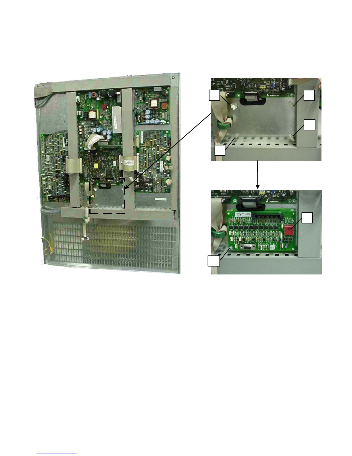
C.4.1 Parallel Card Installation
01
01
02
01
03
08
1. Open the UPS doors
2. Place and fix the new card (position 8) on the UPS door as shows in the picture.
Page | 67
Figure 29 – Parallel Card Installation
Page 78

C.4.2 Parallel Card Connections
Flat DB9 Cable
05
04
04
System Card
02
01
02
01
03
03
07
1. Connect the flat cable DB9(present in the UPS) to the connector J2 in the parallel card
2. Insert the supplied connector (05 position) in J1 of the parallel card
3. Connect the flat cable supplied (04 position) from the connector J3 in the parallel card to the
connector J2 in the system card
Figure 30 – Parallel Card connections
C.4.3 Parallel Card RJ45 Installation
1. Open the options panel
2. Remove the protection metallic panel
3. Place the SK Parallel signal RJ45 (07 position)
Figure 31 – Parallel Card RJ45 Installation
Page | 68
Page 79
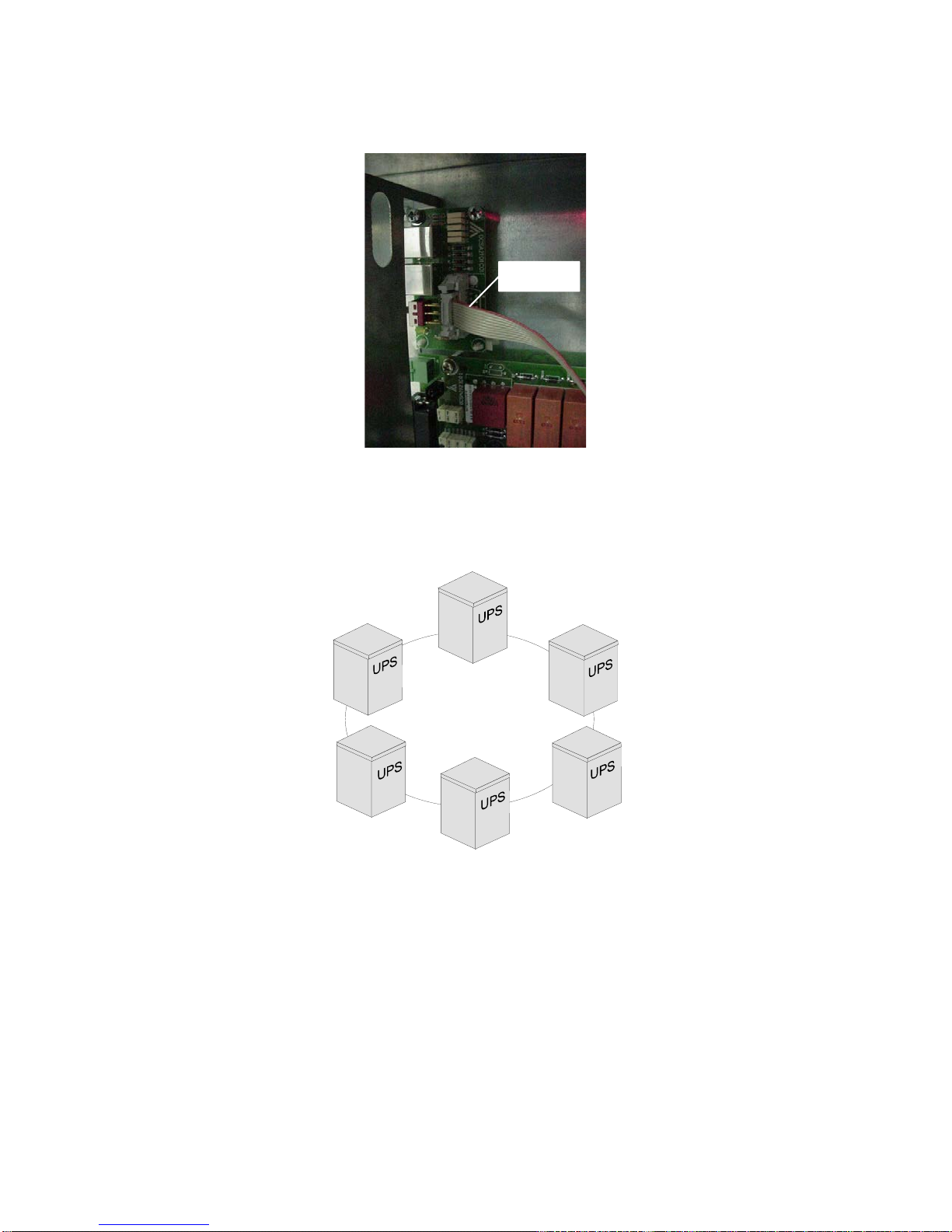
Flat Cable
C.4.4 Parallel Card RJ45 Connections
Connect the flat cable (present in the UPS) to the connector J4 in the parallel card RJ45
Figure 32 – Parallel Card Flat Cable Installation
C.5 Connection of Signals
The signals of several parallel UPS’s are connected in a closed loop configuration; if the loop is
interrupted at any point, either due to a fault or for maintenance, operation of the system is not
compromised, and the system continues to operate normally, as will be shown repeatedly below.
The various UPS’s are connected through the “signals RJ45-flat-adapter” parallel card, located in the
lower part of the UPS.
Page | 69
Figure 33 - Parallel Control Routing
Page 80
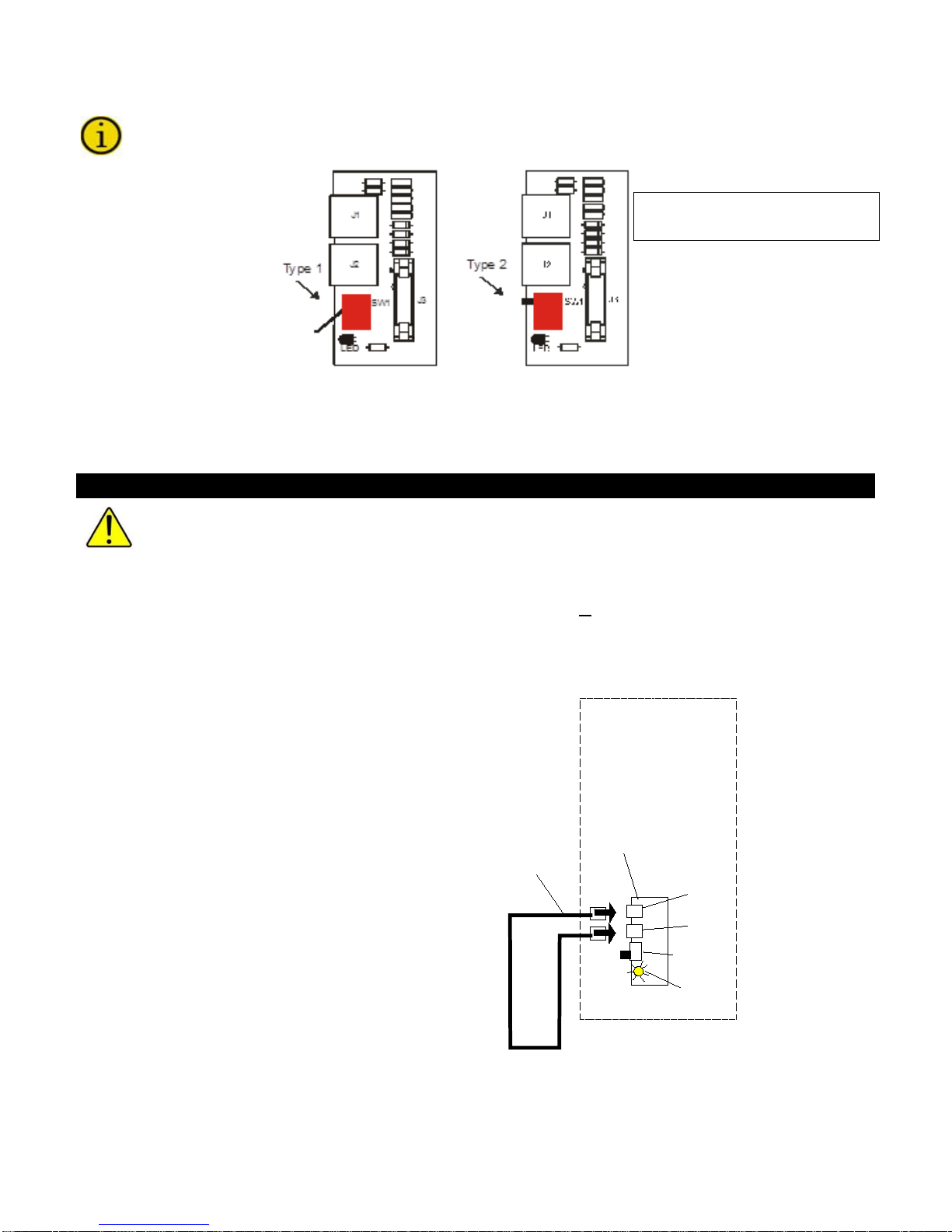
C.5.1 RJ45-flat-adapter signals parallel card.
B
B
C
A
UPS
D
E
LED On SW1 start position
Off SW1 Cont position
Start position
Cont position
The UPS may be provided with one of two versions of the parallel card which differ in the type of
switch used (type 1 or type 2). The difference between the two switches is the position of the
control lever.
J1-RJ45 type connector J2-RJ45 type connector
Figure 34 - RJ45-flat-adapter signals parallel card
Warning
All the parallel-connected UPSes must have the same firmware version. Press key 7 from the
basic menu on the display panel to display the firmware version installed.
For the expansion of an existing system, check that the system has the same firmware version
as the new UPS. Consult the factory if firmware versions are different.
Using the cable with two RJ45 terminals provided with each UPS (A), make the connections as shown
below:
C.5.2 Single UPS Configured in Parallel
If it is required to use a UPS that has been configured as a parallel unit on its own, the signal card must
be jumpered with the cable provided as shown below.
UPS PARALLEL CABLE
A. RJ45 type connector
B. RJ45-flat-adapter signal parallel card
C. LED on
D. SW1 in start position
Figure 35 – Parallel Connection – Single Module
Page | 70
Page 81

C.5.3 Two UPS’s in Parallel
B
B
C
A
UPS 1
D
A
UPS 2
E
A. UPS PARALLEL CABLE
B. RJ45 type connector
C. RJ45-flat-adapter signal parallel card
D. UPS1 LED on, UPS2 LED off
E. SW1 in start position on UPS1, SW1 in cont position on UPS2
Two RJ45 cables are required despite redundancy. System will not start up unless two cables
are installed.
Figure 36 – Parallel Connection – Two Modules
C.5.4 Three UPS’s in Parallel
A. UPS PARALLEL CABLE
B. RJ45 type connector
C. RJ45-flat-adapter signal parallel card
D. UPS1 LED on, UPS2 LED off, UPS3 LED off
E. SW1 in start position on UPS1, SW1 in cont position on UPS2 and UPS3
Three RJ45 cables are required despite redundancy. System will not start up unless three
cables are installed.
Page | 71
Page 82
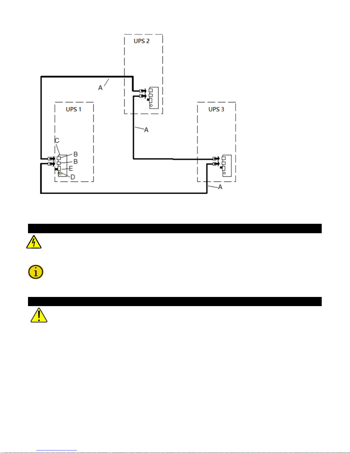
Figure 37 – Parallel Connection – Three Modules
To add other parallel UPS’s, a “UPS PARALLEL CABLE” must be added for each new UPS connected.
Danger
The signal connection must not be removed when one UPS is shut down
C.6 Parallel Start-up procedure
For each UPS, follow the start-up single unit procedure. See Section 3.1.2 Sta r t-Up Procedure
Single Module
It is critical that the following procedure be followed in the sequence given.
Warning
These instructions assumed that the units have been wired properly and the proper installation
tests have been performed by factory authorized personnel.
Page | 72
Page 83

C.7 Parallel Communication Troubleshooting
1) Normal operation, Master unit
1) Normal operation, Master unit with message
For the sake of simplicity, the instructions shown below refer to a system with three UPS’s, but are
equally valid for more complex systems.
C.7.1 Normal Condition
2) Normal operation, Slave unit
3) Normal operation, Slave unit
A - UPS Parallel Cable
C.7.2 Single Opened Parallel Cable
If the signal cable between UPS’s 1 and 3 is open
“Parallel signal cable fault” appears on the panel
2) Normal operation, Slave units with message
“Parallel signal cable fault” on the panel
3) Normal operation, Slave units with message
“Parallel signal cable fault” on the panel
A - UPS Parallel Cable
In this situation the load is powered correctly. All the UPS’s are supplying power to the
load.
Page | 73
Page 84
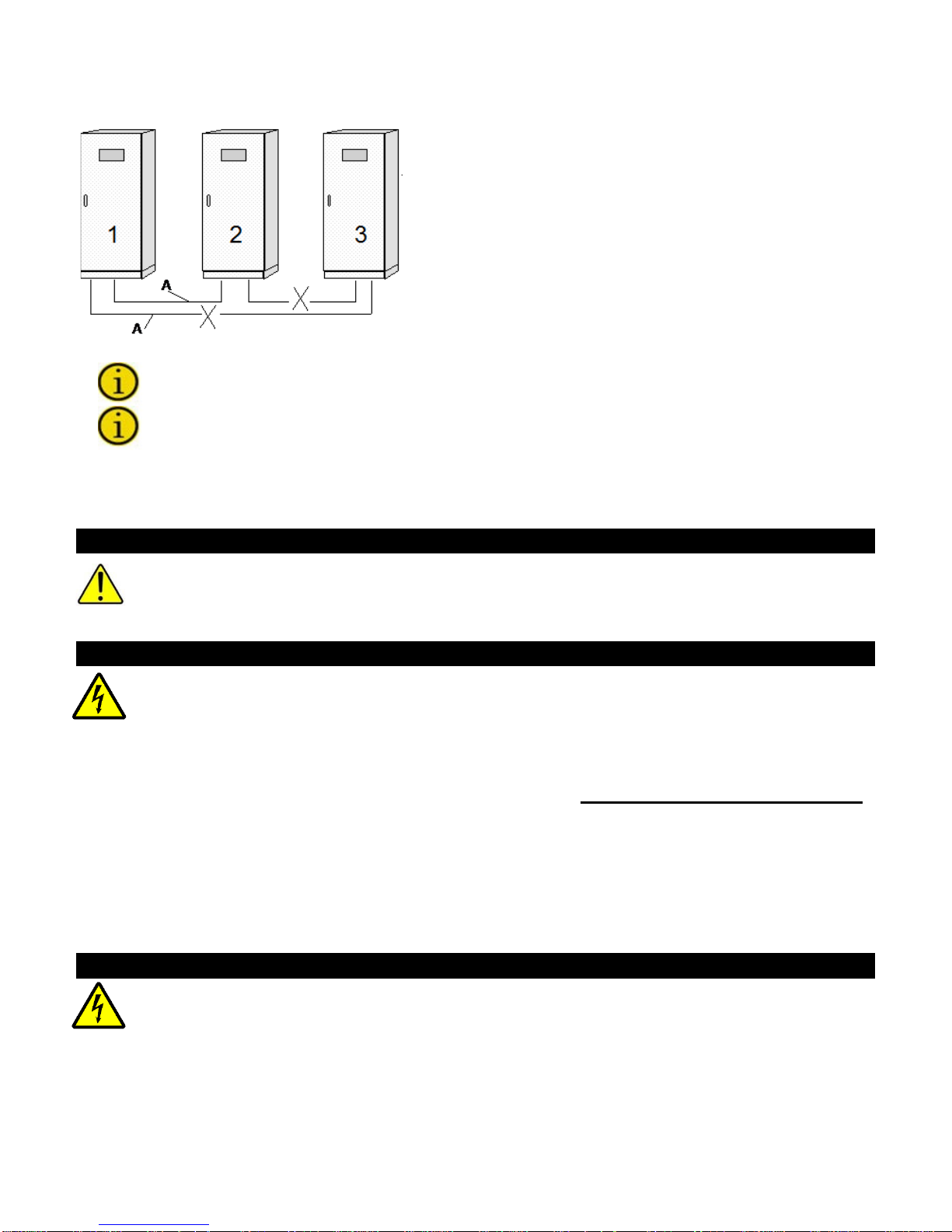
C.7.3 Multiple Opened P arallel Cable
1) Normal operation, Master unit with message
A - UPS Parallel Cable
The signal cables between UPS’s 1, 3 and 2, 3 are opened.
2) Normal operation, Slave units with message
3) Disconnected (TLI open, SCRs off), Slave
“Parallel signal cable fault” on the panel
“Parallel signal cable fault” on the panel
units with message “INTERNAL FAULT 10” on
the panel
In this situation the load is only powered correctly by UPS’s 1 and 2.
To restore the broken signal cable, first the UPS with the message “INTERNAL FAULT 10” on
the panel has to be shut down.
C.8 Mechanical Bypass
The SWMB must not be closed on a UPS that is off and that is connected in parallel with other
units operating normally. This operation may cause a fault on the UPSes which may create a
dangerous voltage at the output. SWMB may be closed with the UPS operating by following the
C.8.1 Mechanical bypass on a single unit
This is the procedure to perform a mechanical bypass operation on a single unit (e.g. UPS1):
Open switches SWBY, SWOUT, SWIN and the battery cabinet circuit breaker/disconnect on unit 1 only.
If the active UPS’s can power the load, the system remains in normal operation and maintenance can be
carried out on UPS1.
procedure described in the section 3.4 Operating Modes
The If SWMB is closed on any unit, the whole system switches to bypass.
If all the switches are then opened to allow maintenance operations to be carried out, all the
power required by the load will switch onto the mechanical bypass line of the unit in which
SWMB has been closed.
WARNING: both the automatic and the mechanical bypass line of each UPS are sized for
the rated power of the single unit.
NOTE To mechanically bypass the entire UPS system the switches SWMB of all the units
must be closed.
When the mechanical bypass switch SWMB is closed lethal voltages are present inside the
UPS. Extreme care must be exercised when performing maintenance on a UPS with mains
voltage present and the SWMB closed. Staco recommends only using the mechanical bypass
for keeping your load powered if the UPS has failed. For maintenance we recommend the use
of a Staco external maintenance bypass switch. Consult the factory for more details.
Warning
Danger
Danger
Page | 74
Page 85
C.8.2 Mechanical bypass on the whole system
The sequences of operations to be carried out to place the system in mechanical bypass are described
below. The procedures vary depending on the initial state:
C.8.2.1 All the UPS are in NORMAL OPERATION
The power supplied to the load is not interrupted in any way;
Warning
The bypass line is present and its frequency and voltage are suitable the UPS display panel
indicates Normal Operation.
1. Close all the switches SWMB (the control logic automatically disables the inverter)
2. Open all the switches on the UPS (SWIN, SWOUT, SWBY and the battery cabinet circuit
breaker/disconnect) and keep only SWMB (mechanical bypass switch) closed. The control
panel remains off.
After carrying out the operations indicated above, personnel must wait at least ten minutes for
the capacitors to discharge before working on the inside of the UPS.
Warning
In this situation any disturbance (such as a blackout) on the mains supply line will have an effect
on the load (since the batteries are deactivated in this state).
C.8.2.2 - Whole System with Output Not Synchronized with the Bypass Line
The power supplied to the load is interrupted; therefore, this operation should be used only if absolutely
necessary.
Warning
The bypass line is outside the acceptable limits; the following message is seen on the display
panel:
BAD BYPASS VOLTAGE or SWBY OFF and the green LED 1 will flash
1. Open all the switches on the UPS (SWIN, SWOUT, SWBY and the battery cabinet circuit
breaker/disconnect). The control panel will remain off.
2. Before closing switches SWMB and connecting the loads, ensure that both the frequency and
voltage of the mains supply are sufficient to power the connected loads.
After carrying out the operations indicated above, personnel must wait at least ten
minutes for the capacitors to discharge before working on the inside of the UPS.
After the maintenance operations have finished, restart the UPS by following the instructions in the
section on Start-Up Procedure (see Section 3.1.2 Start-Up Procedure Single Module) and then open
SWMB (if closed).
The UPS will return to Normal Operation.
Page | 75
Page 86

C.9 Insertion and removal with UPS’s operating (hot swap)
The hot insertion and removal of the UPS can only take place if the system is configured with
the RJ45 female/RJ45 female shielded adaptor cable.
The hot insertion and removal of the UPS makes technical support easier and improves the reliability of
the system.
With this procedure it is not necessary to shut down all the UPS’s in order to add or remove a unit.
Hot insertion and removal can only be done on systems comprising UPS’s with the following
characteristics:
• The UPS system must be prearranged with a distribution panel (for power connections)
• The UPS system must be prearranged with a RJ45 female/RJ45 female shielded adaptor cable
(not provided with the UPS).
• All the UPS’s in the system must have the same firmware version.
C.9.1 Example of Hot Insertion
A) UPS parallel cable type RJ45
B) RJ45 female/RJ45 female shielded adaptor cable UPS BYPASS CABLE
1) Insert the new UPS (power connections in the distribution panel) and keep it switched off. UPS 3:
SW1 cont position
2) Remove adaptor B and insert the new UPS instead of the adaptor.
3) Now switch on UPS 3 (the added UPS).
4) With the lever of SW1 in the start position in one UPS only and the lever in the cont position on all
the others, check that all the UPS’s are operating normally and that the system is sharing the
output power.
Page | 76
Page 87
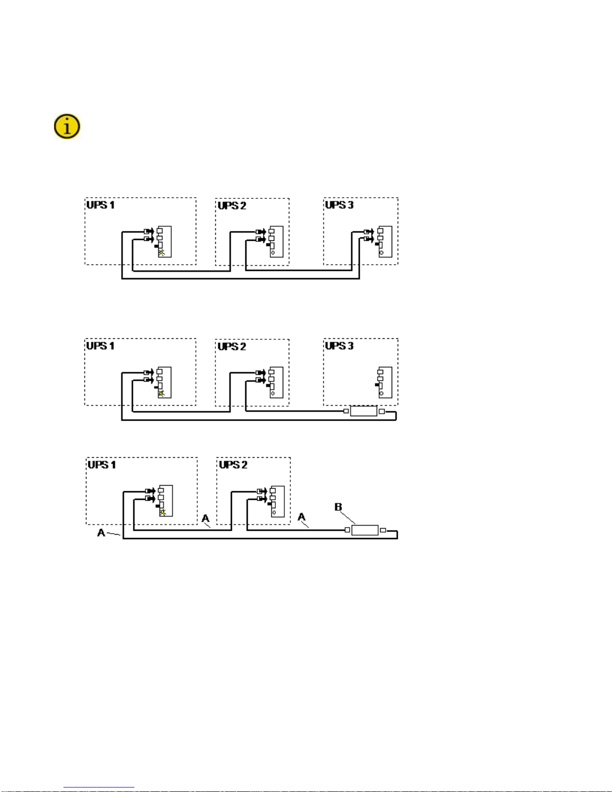
C.9.2 Example of Hot Removal
With hot removal, it is not necessary to shut down all the UPSs of the system in order to remove one.
NOTE: if the UPS to be removed has SW1 in the start position, one of the other UPS’s (UPS 1
or UPS2) must be in the start position. One UPS in the system must have SW1 in the start
position and LED ON.
1) Shut down the UPS (3) that is to be removed. Remove the signal cables of the UPS to be
removed.
A) UPS parallel cable type RJ45
B) RJ45 female/RJ45 female shielded adaptor cable UPS BYPASS CABLE
2) Connect the RJ45 female/RJ45 female shielded adaptor cable (not provided) between cables A
3) Check that all the UPS’s are operating normally and that the system is sharing the output power.
Page | 77
 Loading...