

Page 1

The FIRSTLINE UPS
Form No.003-2323 Rev B 09/04/2009
301 Gaddis Boulevard • Dayton, Ohio 45403
U.S. Toll Free 866-261-1191
(937) 253-1191 • Fax: (937) 253-1723
Web site: www.stacoenergy.com
User’s Manual
25KVA, 30KVA, AND 37.5KVA
Page 2

Before Installing the UPS:
-Read all safety and installation instructions.
-Make sure that the UPS is the correct model for your application.
-Verify that the available power source matches the input rating of the UPS. Unless the
UPS is in the tall cabinet and is equipped with a transformer option, the source should be
120 volts line to neutral, three phase, ABC sequence, with a grounded neutral.
Before starting the UPS:
-Read all safety and operating instructions.
-Verify that the UPS is installed in a clean, temperature controlled area.
-If the UPS is installed at an altitude above 1000 meters, the output load capability must be
derated by 1% for each 100 meters above 1000 meters.
-Verify that the installation includes an input breaker of the proper rating.
-Verify that the wiring is correct and that all connections are neat and tight.
-Verify that the internal batteries have been connected.
-If an optional Extended Run Time Battery Cabinet is present, verify that it is equipped with
the optional breaker or that an external breaker has been provided as part of the
installation. The battery breaker should be closed before the UPS is started.
-Make sure that single phase loads are fairly evenly distributed across the three output
phases. Balanced operation maximizes efficiency and reliability. (Check the individual
output phase currents when the UPS is operating)
.
Page 3

FirstLine UPS
CONTENTS
Section 1 .............................................................................................................................. 1
Introduction ....................................................................................................................... 1
FirstLine UPS Part Number System ................................................................................. 2
Battery Option ................................................................................................................... 2
Accessories ...................................................................................................................... 3
Section 2 .............................................................................................................................. 4
Safety Warnings ............................................................................................................... 4
Section 3 .............................................................................................................................. 6
UPS Setup ........................................................................................................................ 6
Inspecting The Equipment ................................................................................................ 6
Floor Loading .................................................................................................................... 6
Clearances ....................................................................................................................... 6
Unloading the Cabinet(s) .................................................................................................. 7
Placing The Cabinet ....................................................................................................... 10
Section 4 ............................................................................................................................ 11
Electrical Installation ....................................................................................................... 11
Wiring Preparation .......................................................................................................... 11
Wiring Installation ........................................................................................................... 13
Wiring Specifications and Diagrams ............................................................................... 15
Removing and Replacing The Front Panel ..................................................................... 18
Connect The Internal Battery .......................................................................................... 18
Section 5 ............................................................................................................................ 20
Communication ............................................................................................................... 20
Customer Interface ......................................................................................................... 20
Section 6 ............................................................................................................................ 22
Operation ........................................................................................................................ 22
Display Functions ........................................................................................................... 24
Section 7 ............................................................................................................................ 25
Initial Start Up ................................................................................................................. 25
Normal Operation ........................................................................................................... 25
Manual Transfer to Bypass ............................................................................................. 26
Manual Transfer to Inverter ............................................................................................ 26
External Bypass Arrangement ........................................................................................ 26
Automatic Transfer To Bypass ....................................................................................... 27
Automatic Transfer To Inverter ....................................................................................... 27
OverLoad ........................................................................................................................ 28
Inverter ........................................................................................................................ 28
Bypass ........................................................................................................................ 28
Rectifier ....................................................................................................................... 28
Section 8 ............................................................................................................................ 29
Battery Removal, Installation, and Service ..................................................................... 29
Polarity Verification Procedure ....................................................................................... 32
Stopping the Rectifier in the UPS ................................................................................... 33
UPS Maintenance ........................................................................................................... 34
Battery Fuse Replacement ............................................................................................. 35
Section 9 ............................................................................................................................ 37
Optional FirstLine Extended Run Time Battery Cabinet ................................................. 37
Section 10 .......................................................................................................................... 38
FirstLine UPS Technical Specifications .......................................................................... 38
Form No. 003-2323 Rev B
Page 4

FirstLine UPS
Table 1-Part Numbering System .......................................................................................... 2
Table 2-Symbols .................................................................................................................. 4
Table 3-Model Floor Loadings .............................................................................................. 6
Table 4-Input/Output Terminal ........................................................................................... 13
Table 5-Ground Lugs ......................................................................................................... 13
Table 6-FirstLine UPS 10-20kVA Current Requirements ................................................... 14
Table 7-Terminal Block Wiring ........................................................................................... 16
Table 8-Torque Values for TB1, 2, 3, 4 .............................................................................. 21
Table 9-Indicator Status and Description ........................................................................... 23
Table 10-Menu Map for Display Functions ......................................................................... 24
Figure 1-The FirstLine UPS 25-37.5kVA .............................................................................. 1
Figure 2-UPS on pallet ......................................................................................................... 7
Figure 3-Shipping Bracket .................................................................................................... 8
Figure 4-Lifting fork area ...................................................................................................... 9
Figure 5-Leveling foot being adjusted down to the floor ..................................................... 10
Figure 6-Bottom View ......................................................................................................... 12
Figure 7-Terminal Blocks ................................................................................................... 13
Figure 8-UPS Wiring-Single Line Diagram ......................................................................... 17
Figure 9-Removing the UPS Front Panel ........................................................................... 18
Figure 10-Internal Battery ................................................................................................... 19
Figure 11-Communication Options and Control Terminals ................................................. 20
Figure 12-TB3 .................................................................................................................... 21
Figure 13-TB4 .................................................................................................................... 21
Figure 14-FirstLine Front Panel Display and Control Module ............................................. 22
Figure 15-Battery Tray ....................................................................................................... 29
Figure 16-Battery Tray ....................................................................................................... 30
Figure 17-Battery Installation ............................................................................................. 31
Figure 18-The FirstLine Extended Run Time Battery Cabinet ............................................ 37
Form No. 003-2323 Rev B
Page 5
FirstLine UPS
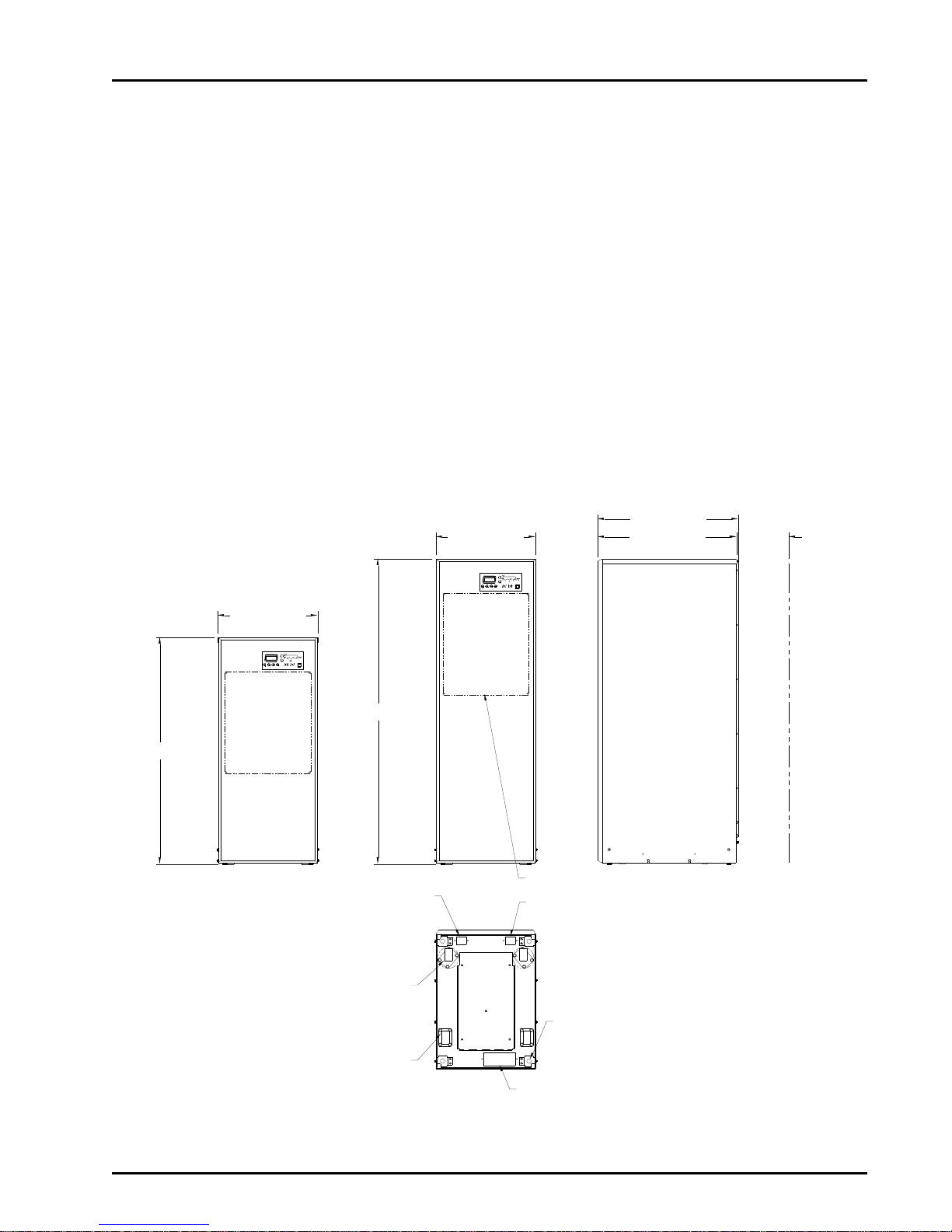
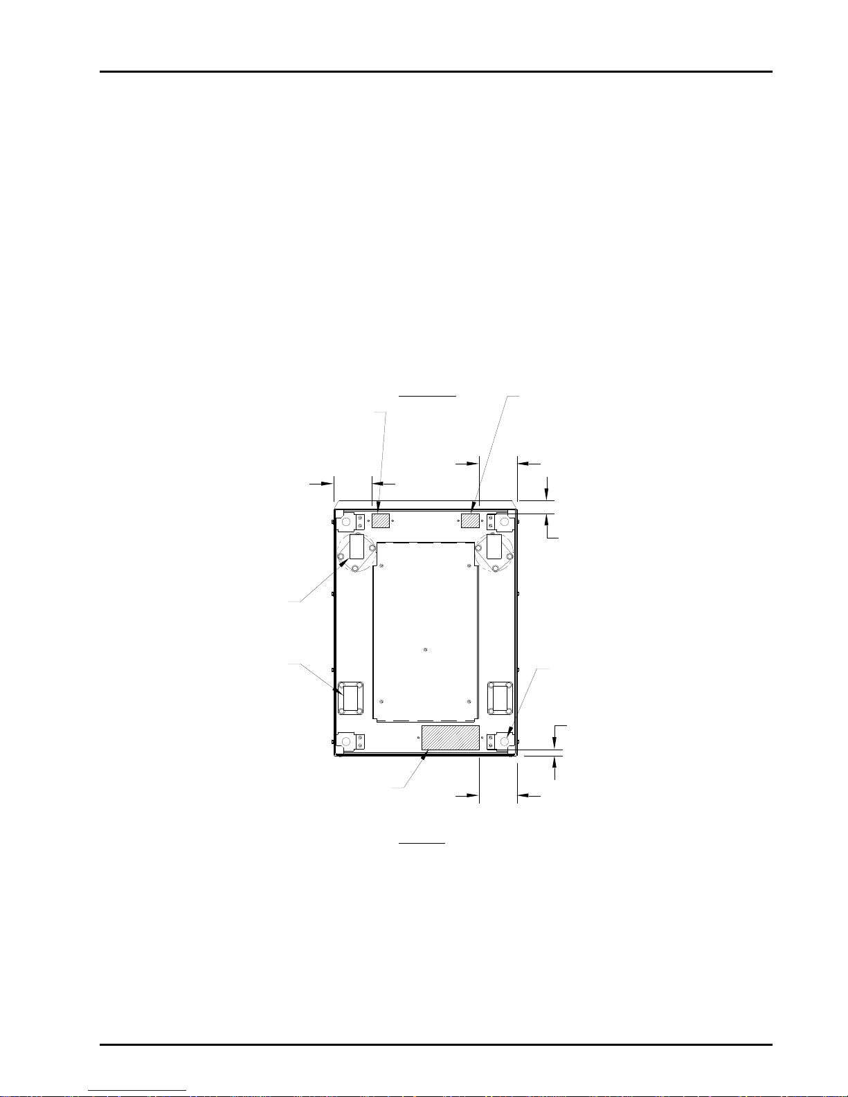
ESC
+
EPO
23.00 [584.2mm]
70.00 [1778.0mm]
FOR VENTILATION
WALL CLEARANCE
12.00 [304.8mm] MIN.31.94 [811.2mm]
23.00 [584.2mm]
52.00 [1320.8mm]
EPO
+
ESC
(2) RIGID CASTERS
(2) SWIVEL CASTERS
POWER CABLE ENTRY
7.25 [184.2mm] X 3.00 [76.2mm]
(4) LEVELING FEET
INTAKE VENTILATION HOLES
EXTERNAL BATTERY POWER CABLE ENTRY
2.25 [57.2mm] X 1.75 [44.5mm]
EXTERNAL BATTERY CONTROL
CABLE ENTRY
2.25 [57.2mm] X 1.75 [44.5mm]
32.38 [822.4mm]
SECTION 1
Introduction
The FirstLine uninterruptible power supply (UPS) is a true online, double-conversion, threephase system that can be used to prevent loss of valuable electronic information and
minimize equipment downtime. It is ideal for protecting essential information technology
and electrical engineering infrastructure in corporate, telecom, health care, banking, and
industrial applications.
The FirstLine UPS continually monitors incoming electrical power and removes surges,
spikes, sags, and other irregularities that are inherent in commercial utility power. Working
with a building’s electrical systems, the UPS supplies clean, consistent power that sensitive
electronic equipment requires for reliable operation. During brownouts, blackouts, and other
power interruptions, batteries provide emergency power to safeguard operation.
Figure 1 shows two versions available: Short cabinet for compact 208/208 or 220/220
requirements and the tall cabinet for extended run time built in, or 480V I/O.
Form No. 003-2323 Rev B 1
Figure 1-The FirstLine UPS 25-37.5kVA
Page 6

Full Part Number
kVA
Input Voltage
Output
Voltage
Run
Time
(min.)
Cabinet
Basic Part
No.
Battery
Option
Other
Options
25
208Y/120
208Y/120
11
Short
FLU-25S-20
-1
480
208Y/120
11
Tall
FLU-25T-42
-1
-I
480
480Y/277
11
Tall
FLU-25T-44
-1
-I
208Y/120
208Y/120
28
Tall
FLU-25T-20
-2
208Y/120
208Y/120
11
Tall
FLU-25T-20
-1
-I
220Y/127
220Y/127
11
Short
FLU-25S-22
-1
220Y/127
220Y/127
31
Tall
FLU-25T-22
-2 30
208Y/120
208Y/120
8
Short
FLU-130S-20
-1
480
208Y/120
8
Tall
FLU-30T-42
-1
-I
480
480Y/277
8
Tall
FLU-30T-44
-1
-I
208Y/120
208Y/120
22
Tall
FLU-30T-20
-2
208Y/120
208Y/120
8
Tall
FLU-30T-20
-1
-I
220Y/127
220Y/127
11
Short
FLU-30S-22
-1
220Y/127
220Y/127
24
Tall
FLU-30T-22
-2
37.5
208Y/120
208Y/120
5
Short
FLU-37S-20
-1
480
208Y/120
5
Tall
FLU-37T-42
-1
-I
480
480Y/277
5
Tall
FLU-37T-44
-1
-I
208Y/120
208Y/120
16
Tall
FLU-37T-20
-2
208Y/120
208Y/120
5
Tall
FLU-37T-20
-1
-I
220Y/127
220Y/127
5
Short
FLU-37S-22
-1
220Y/127
220Y/127
17
Tall
FLU-37T-22
-2
Other Options
Suffix
Notes
Isolation Transformer
-I
Isolation transformer required for use with delta (3wire) input. Standard is K20 rated.
FirstLine UPS Part Number System
Table 1-Part Numbering System
FirstLine UPS
Battery Option
-1 = 1 string
-2 = 2 string
-0 = Without Batteries
220V Models are not listed to UL, CUL, or CSA.
Form No. 003-2323 Rev B 2
Page 7

FirstLine UPS
Accessories
There are several external accessories that are designed to work with the FirstLine UPS:
The FirstLine Extended Run Time Battery Cabinet allows the addition of up to three
additional battery strings per cabinet to increase the available battery run time. Up to
three FirstLine Extended Run Time Battery Cabinets can be used with each UPS.
The cabinet is styled to match the FirstLine UPS. The battery cabinet can be ordered
with an optional disconnect switch or a user provided disconnect arrangement can
be used. The FirstLine Extended Run Time Battery Cabinet is listed to UL1778.
The FirstLine Options Cabinet is a steel enclosure designed to hold option devices
to be used in conjunction with the FirstLine UPS. The enclosure is styled to match
the UPS and includes provisions for terminating a number of conduits to facilitate
wiring. Available option devices include several transformers, a Maintenance Bypass
Switch (MBS), output panelboards, and output meters. The FirstLine Options
Cabinet is listed to UL1778.
The FirstLine Wall-Mounted Maintenance Bypass Switch is the same MBS switch
arrangement that is available in the Options Cabinet, but in a more compact
enclosure that mounts on a wall. The FirstLine Wall-Mounted Maintenance Bypass
Switch is listed to UL1778.
The FirstLine UPS is also available together with the FirstLine Extended Run Time
Battery Cabinet to form the FirstLine UPS Emergency Lighting System which is
listed to UL924.
Contact Staco Energy Company, your tailored power solutions provider, for
additional information.
Form No. 003-2323 Rev B 3
Page 8

FirstLine UPS
Danger / Risk of Electric Shock
Caution
Risk of Explosion
Note
Ground Connection
Electrostatic Sensitive Device
IMPORTANT SAFETY INSTRUCTIONS
SAVE THESE INSTRUCTIONS
SECTION 2
Safety Warnings
This manual contains important instructions that you should follow during installation and
maintenance of the UPS and batteries. Please read all instructions before operating the
equipment and save this manual for future reference.
READ AND FOLLOW ALL SAFETY INSTRUCTIONS
a. Do not use outdoors.
b. Do not route wiring across or near hot surfaces.
c. Do not install near gas or electric heaters.
d. Use caution when servicing batteries. Battery acid can cause burns to skin and
eyes. If acid is spilled on skin or in eyes, flush acid with fresh water and contact
a physician immediately.
e. Equipment should be installed where it will not readily be subjected to tampering
by unauthorized personnel.
f. The use of accessory equipment not recommended by the manufacturer may
cause an unsafe condition.
g. Do not use this equipment for other than intended use.
Table 2-Symbols
Form No. 003-2323 Rev B 4
Page 9

FirstLine UPS
DANGER
WARNING
CAUTION
This UPS contains LETHAL VOLTAGES. All repairs and service should be
performed by AUTHORIZED SERVICE PERSONNEL ONLY. There are NO
USER SERVICEABLE PARTS inside the UPS.
This UPS contains its own energy source (batteries). The UPS output may
carry live voltage even when the UPS is not connected to an AC supply.
To reduce the risk of fire or electric shock, install this UPS in a temperature
and humidity controlled, indoor environment, free of conductive contaminants.
Do not operate near water or excessive humidity (95% maximum).
Input and output over-current protection and disconnect switches must be
provided by others.
Batteries can present a risk of electrical shock or burn from high short circuit
current. Observe proper precautions. Servicing should be performed by qualified
service personnel knowledgeable of batteries and required precautions. Keep
unauthorized personnel away from batteries.
Risk of explosion if batteries are replaced by an incorrect type. Replace with same
type and rating only.
Proper disposal of batteries is required. Refer to your local codes for disposal
requirements.
Never dispose of batteries in a fire. Batteries may explode when exposed to flame.
Form No. 003-2323 Rev B 5
Page 10

FirstLine UPS
STANDARD MODEL FLOOR LOADING
25-30-37.5 KVA
Maximum Weight
Point Loading
Standard
1253 Lbs (568 kg)
399 lb/in2 (28 kg/cm2)
Extended Run
1765 Lbs (801 kg)
562 lb/in2 (39 kg/cm2)
480 I/O
1855 Lbs (841 kg)
590 lb/in2 (42 kg/cm2)
From Front of Cabinet
36” (91.4 cm) working space
From Back of Cabinet
12” (30.5 cm)
From Side of Cabinet
Minimum 24” (61 cm)
SECTION 3
UPS Setup
This section describes:
Equipment inspection
Floor loading and clearances
Removing and replacing the cabinet panels
Unloading the cabinet(s)
Inspecting The Equipment
If any equipment has been damaged during shipment, keep the shipping and packing
materials for the carrier or place of purchase and file a claim for shipping damage. If you
discover damage after acceptance, file a claim for concealed damage.
To file a claim for shipping damage or concealed damage: 1) File with the carrier within 15
days of receipt of the equipment, 2) Send a copy of the damage claim within 15 days to
your service representative.
Floor Loading
When planning the installation, consider the UPS weight for floor loading. The strength of
the installation surface must be adequate for point and distributed loading. The
approximate weights are shown in the following table.
Table 3-Model Floor Loadings
Clearances
The following clearances are recommended for the FirstLine UPS.
Form No. 003-2323 Rev B 6
Page 11
FirstLine UPS
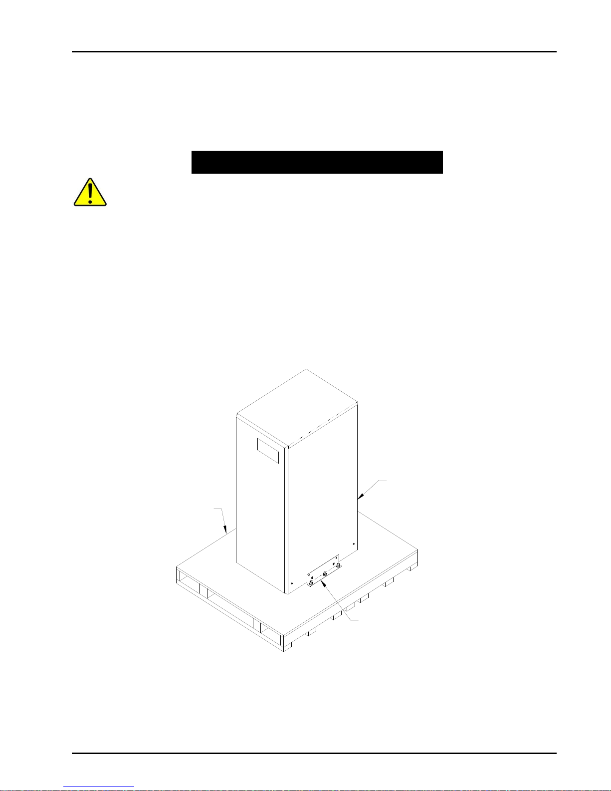
Pallet
Shipping bracket - (1) this
side and opposite side
Forklift access
from rear
CAUTION
Unloading the Cabinet(s)
The following tools are required for unloading the cabinet(s):
Wrenches for 1/4” bolts and 1/2” nut
Forklift
The UPS and optional cabinets are heavy (see Table 3). Unloading the cabinets
requires at least two people to safely remove the cabinets from the pallet.
To remove the UPS or optional cabinets from the ship pallet:
1. Remove all banding, wrapping, and foam protectors.
2. Loosen the six 1/2” nuts and washers securing the shipping brackets to the pallet
(see Figures 2 and 3).
3. Remove and discard the four 1/4” bolts and washers securing the shipping brackets
to the cabinet side panels. Also remove the four ¼” bolts and washers the bracket
surrounds but does not touch. Save these as they must be reinstalled later. Pull the
brackets away from the cabinet.
Form No. 003-2323 Rev B 7
Figure 2-UPS on pallet
Page 12
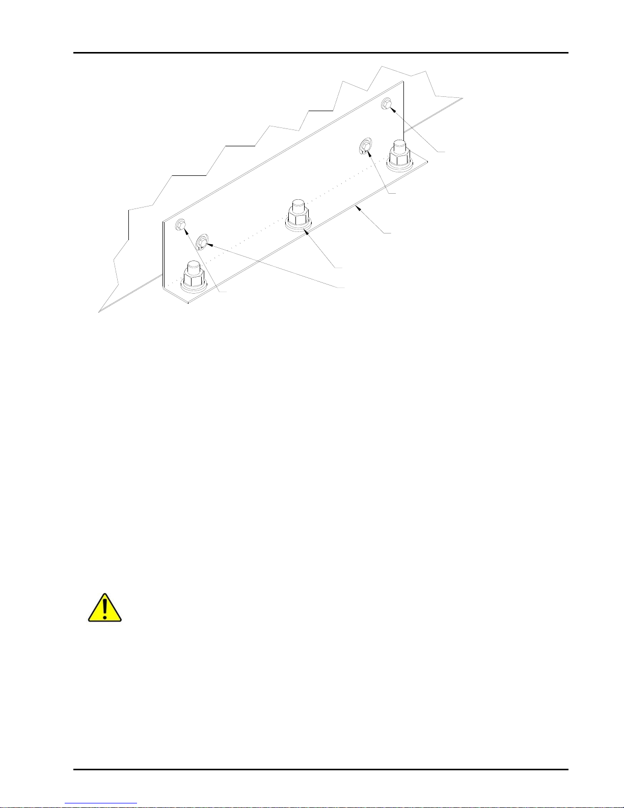
FirstLine UPS
Remove and discard
1/4" bolt and washers
(4) places
Remove and discard
1/4" bolt and washers
(4) places
Pull (2) shipping brackets
away from cabinet.
Loosen (3) 1/2" nuts on each bracket
Remove (4) 1/4" bolts.
Reinstall after the unit is on the floor
Remove (4) 1/4" bolts.
Reinstall after the unit is on the floor
Figure 3-Shipping Bracket
4. Remove the front cover (see Figure 9) before inserting the lifting forks.
5. Ensure that the four (4) leveling feet are raised so that they will not touch the floor
when the cabinet is placed on the floor.
6. Lift the cabinet with a forklift from the rear of the unit, one to two inches (1”-2” [2.55cm]) above the pallet (see figure 5).
7. Slide the pallet completely away from the raised cabinet.
8. Slowly lower the cabinet to the floor or other appropriate flat service.
9. Reinstall the front cover and add (4) ¼” bolts and washers (see figure 3).
10. Roll the cabinet to the desired location
11. Do not move the cabinet to another location by forklift , as the cabinets are heavy
and may fall.
DO NOT ALLOW THE FORKLIFT TO MOVE WHILE THE CABINET IS
RAISED, ONLY MOVE THE CABINET VERTICALLY TO REMOVE THE
PALLET FROM UNDER THE CABINET.
Form No. 003-2323 Rev B 8
Page 13
FirstLine UPS
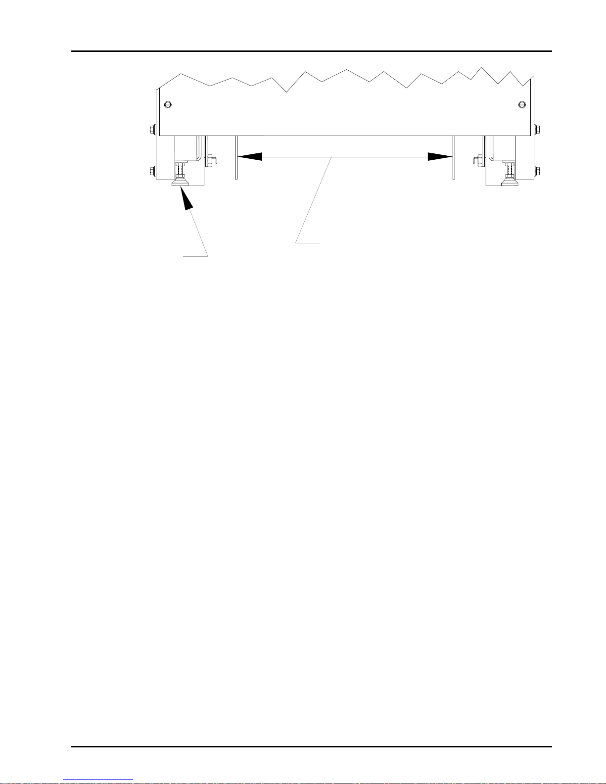
Place forks in this area
so as not to damage the
leveling feet or casters.
Set forks to a maximum
13 inches at outside width.
Leveling foot
13.00" [330mm] Max.
Figure 4-Lifting fork area
Form No. 003-2323 Rev B 9
Page 14

FirstLine UPS
Lower the leveling foot
to the floor to secure
the UPS in position
Placing The Cabinet
Once the cabinet has been rolled into position, remove the front panel to access the front
leveling feet by pulling the panel outward at the bottom of the unit until it unsnaps and then
lift up and off the cabinet (see figure 9). Adjust the leveling feet as shown in figure 5.
Figure 5-Leveling foot being adjusted down to the floor
Form No. 003-2323 Rev B 10
Page 15

FirstLine UPS
WARNING
SECTION 4
Electrical Installation
The FirstLine has the following power connections:
3-phase (L1, L2, andL3), neutral, and ground connection for rectifier/bypass input
3-phase (L1, L2, and L3), neutral, and ground connection for load output
The input neutral connection is not used when the UPS is equipped with the optional
isolation transformer.
The nominal input/output voltages are:
120/208 VAC is available in the short cabinet or tall cabinet.
208 VAC, 60 Hz delta input is available when using the tall cabinet with an input
isolation transformer.
127/220 VAC is available in the short or tall cabinet.
480V, 60 Hz input is available when using the tall cabinet with an input transformer,
(isolation or auto.)
480/480 Vac is available when using the tall cabinet with an input and output
transformer.
Input and output over current protection and disconnect switch must be provided by others.
Only qualified service personnel (such as a licensed electrician) should perform the
UPS installation and initial startup. Risk of electrical shock.
Wiring Preparation
To begin wiring the UPS:
1. Verify that the electrical connections to the installation site have been properly
installed.
2. A wall-mounted, user-supplied, readily-accessible disconnection device must be
incorporated in the input wiring.
Compare the circuit breaker ratings to the ones in Table 6 on page 14.
Form No. 003-2323 Rev B 11
Page 16
FirstLine UPS
1.62 [41.3mm]
4.75 [120.7mm]
(4) LEVELING FEET
.81 [20.6mm]
4.75 [120.7mm]
(2) SWIVEL CASTERS
(2) RIGID CASTERS
FRONT
REAR
EXTERNAL BATTERY POWER
CABLE ENTRY
2.25 [57.2mm] X 1.75 [44.5mm]
EXTERNAL BATTERY CONTROL
CABLE ENTRY
2.25 [57.2mm] X 1.75 [44.5mm]
4.75 [120.7mm]
POWER CABLE ENTRY
7.25 [184.2mm] X 3.00 [76.2mm]
3. Switch off utility power to the distribution point where the UPS will be connected. Be
absolutely sure there is no power.
4. Determine your equipment’s grounding requirements according to your local
electrical code.
5. Remove the UPS rear panel.
6. Conduit landing plates are located at the rear bottom of the base to accommodate
bottom wire entry to the cabinet (see figure 6).
Remove plate and drill or punch hole to fit conduit bushing with Greenlee punch or similar
device. Make certain that the bushing will be clear in the opening in the base. Mount
bushing to plate and tighten to manufacturer’s recommendations. Replace the plate and
mount conduit.
Figure 6-Bottom View
Form No. 003-2323 Rev B 12
Page 17

FirstLine UPS
NOTICE
FOR SUPPLY CONNECTIONS,
USE WIRES SUITABLE FOR AT
LEAST 75°C
A B C N
OUTPUT
INPUT
NCBA
INPUT/OUTPUT TERMINAL TIGHTENING TORQUE
#2/0 - #6 AWG
120 inch-pounds
#8 - #12 AWG
50 inch-pounds
GROUND LUGS TIGHTENING TORQUE
#10 AWG
35 inch-pounds
#8 AWG
40 inch-pounds
#4 - #6 AWG
45 inch-pounds
#1/0 - #2 AWG
50 inch-pounds
Wiring Installation
1. Unscrew and remove the rear panel.
2. Connect the input wires to the proper terminals shown in Figure 7. Insure proper
phase rotation. Input neutral is not required if the UPS is equipped with an optional
input isolation transformer.
3. Connect the output wires to the proper terminals shown in Figure 7.
4. Replace the rear panel.
Table 4-Input/Output Terminal
Table 5-Ground Lugs
Figure 7-Terminal Blocks
Form No. 003-2323 Rev B 13
Page 18

UPS
Rating
Input
Voltage
Input
Transformer
Option
Max. Input
Current (A)
Allowed for
Specified
Branch
Protector
Maximum
Allowable Branch
Circuit Protection
(A)
25 kVA
208 V
None
80
100
25 kVA
208 V
Isolation
80
100
25 kVA
220 V
None
80
100
25 kVA
480 V
Standard auto
40
50
25 kVA
480 V
Isolation
40
50
30 kVA
208 V
None
100
125
30 kVA
208 V
Isolation
100
125
30 kVA
220 V
None
100
125
30 kVA
480 V
Standard auto
48
60
30 kVA
480 V
Isolation
48
60
37 kVA
208 V
None
120
150
37 kVA
208 V
Isolation
120
150
37 kVA
220 V
None
120
150
37 kVA
480 V
Standard auto
60
75
37 kVA
480 V
Isolation
60
75
UPS
Rating
Output
Voltage
Rated Max.
Output Current
(A)
(note 2)
Maximum
Allowable
Circuit
Protection (A)
PF=.8
PF=1
25 kVA
208 V
70
55
(note 1)
25 kVA
220 V
66
52
(note 1)
25 kVA
480 V
30
24
50
30 kVA
208 V
83
66
(note 1)
30 kVA
220 V
78
63
(note 1)
30 kVA
480 V
36
29
60
37 kVA
208 V
104
83
(note 1)
37 kVA
220 V
98
78
(note 1)
37 kVA
480 V
45
36
75
Table 6-FirstLine UPS 25-37.5 kVA Current Requirements
FirstLine UPS
Note 1: Output circuit protection requirement determined by distribution circuit.
Note 2: Do not apply continuous loads in excess of rated maximum output current. If the power factor of
Form No. 003-2323 Rev B 14
the load is not known, use PF=1. The UPS controls will permit transient loads within the limits
described in the OVERLOAD section of this manual.
Page 19

FirstLine UPS
Note: Input neutral must be wired for proper operation or the UPS will not start.
Note: Do not over-tighten the screws; be sure to use the specified tightening
torque values shown in Table 4, Table 5, and Table 6.
Wiring Specifications and Diagrams
25 KVA, 208V: CAUTION to reduce the risk of fire, connect only to a circuit provided with
100 amperes maximum branch circuit protection in accordance with the
National Electrical Code, ANSI/NFPA 70.
25 KVA, 480V: CAUTION to reduce the risk of fire, connect only to a circuit provided with
50 amperes maximum branch circuit protection in accordance with the
National Electrical Code, ANSI/NFPA 70.
30 KVA, 208V: CAUTION to reduce the risk of fire, connect only to a circuit provided with
125 amperes maximum branch circuit protection in accordance with the
National Electrical Code, ANSI/NFPA 70.
30 KVA, 480V: CAUTION to reduce the risk of fire, connect only to a circuit provided with
60 amperes maximum branch circuit protection in accordance with the
National Electrical Code, ANSI/NFPA 70.
37.5 KVA, 208V: CAUTION to reduce the risk of fire, connect only to a circuit provided with
150 amperes maximum branch circuit protection in accordance with the
National Electrical Code, ANSI/NFPA 70.
37.5 KVA, 480V: CAUTION to reduce the risk of fire, connect only to a circuit provided with
75 amperes maximum branch circuit protection in accordance with the
National Electrical Code, ANSI/NFPA 70.
220V units should be equipped with the same maximum rated breaker as 208V units.
Form No. 003-2323 Rev B 15
Page 20

UPS
Rating
Voltage
Input
Transformer
Type
Phase
Conductor
Min/Max
Neutral
Conductor
Min/Max
Neutral Conductor with
non-linear loads
Min/Max
Ground Wire
Min/Max
25kva
208/120
NA
#2/2-0
#2/2-0
#2/2-0
#8/1-0 208
isolation
#2/2-0
(none)
(none)
#8/1-0
220/127
NA
#2/2-0
#2/2-0
#2/2-0
#8/1-0
480/277
auto
#4/2-0
#4/2-0
#4/2-0
#10/1-0 480
isolation
#4/2-0
(none)
(none)
#10/1-0
30kva
208/120
NA
#1-0/2-0
#1-0/2-0
#1-0/2-0
#6/1-0 208
isolation
#1-0/2-0
(none)
(none)
#6/1-0
220/127
NA
#1-0/2-0
#1-0/2-0
#1-0/2-0
#6/1-0
480/277
auto
#4/2-0
#4/2-0
#4/2-0
#10/1-0 480
isolation
#4/2-0
(none)
(none)
#10/1-0
37.5kva
208/120
NA
#1-0/2-0
#1-0/2-0
#1-0/2-0
#6/1-0
208
isolation
#1-0/2-0
(none)
(none)
#6/1-0
220/127
NA
#1-0/2-0
#1-0/2-0
#1-0/2-0
#6/1-0
480/277
auto
#3/2-0
#3/2-0
#3/2-0
#8/1-0
480
isolation
#3/2-0
(none)
(none)
#8/1-0
OUTPUT-Minimum wire size required to support rated load. Smaller wire may be used if rated
load current is not needed and the appropriate circuit protection is applied.
UPS
Rating
Voltage
Output
Transformer
Type
Phase
Conductor
Neutral
Conductor
Neutral Conductor with
non-linear loads
Ground Wire
25 kVA
208/120
NA
#2
#2
#2
#8/1-0
220/127
NA
#2
#2
#2
#8/1-0
480/277
auto
#4
#4
#4
#10/1-0
30 kVA
208/120
NA
#1
#1
#1
#6/1-0
220/127
NA
#1
#1
#1
#6/1-0
480/277
auto
#4
#4
#4
#10/1-0
37.5kVA
208/120
NA
#1-0
#1-0
#1-0
#6/1-0
220/127
NA
#1-0
#1-0
#1-0
#6/1-0
480/277
auto
#4
#4
#4
#8/1-0
Table 7-Terminal Block Wiring
FirstLine UPS
Note: No output circuit protection is required if the output conductor sizes are at least as large as
the input conductors, unless the UPS is equipped with an input isolation transformer. If the UPS is
equipped with an input isolation transformer, the UPS is considered a separately derived source
and circuit protection for the output conductors must be provided.
Use at least 75°C-rated copper wire. Minimum wire size is based on 120/208 full load ratings
applied to NEC Code Table 310-16. Code may require a large AWG size than shown in this table
because of temperature, number of conductors in the conduit, or long service runs. Follow local
requirements.
Form No. 003-2323 Rev B 16
Page 21

FirstLine UPS
INPUT
OUTPUT
+
-
(NONE)
NO BATTERY
(OPTION)
(OPTION)
BATTERY
EXTERNAL
EXTENDED
BATTERY
(OPTION)
(STANDARD)
BATTERY
(480Y)
(OPTION)
AUTOTRANFORMER
208Y
(STANDARD)
RECTIFIER
INVERTER
STATIC
SWITCH
(STANDARD)
208Y
TRANSFORMER OPTIONS OR
EXTENDED BATTERY REQUIRE
"TALL" CABINET.
(SAME FOOTPRINT AS "SHORT" CABINET)
220Y INPUT/ 220Y OUTPUT
MODELS ARE ALSO AVAILABLE.
(OPTION)
TRANSFORMER
(480Y)
-
+
-
+
ISOLATION
TRANSFORMER
(OPTION)
(208 )
(480 )
Per NEC article 300-20(2), all three-phase conductors must be run in the same conduit. Neutral and
ground must be run in the same conduit as the phase conductors.
Conduit to be sized to accommodate one neutral conductor the same size as the phase conductor
and one ground conductor. If two neutral conductors or an oversized neutral conductor are to be
installed, check the size of the conduit needed to accommodate the extra wire or size and use that
conduit size in place of the conduit size listed. Conduit sizes can be chosen from NEC Table C1,
type letters RHH, RHW, RHW-2, TW, THW, THHW, THW-2.
Figure 8-UPS Wiring-Single Line Diagram
Form No. 003-2323 Rev B 17
Page 22

FirstLine UPS
BALL STUD CATCH
SHOULDER SCREW
KEYHOLE SLOT
Removing and Replacing The Front Panel
1. Pull the top of the panel outward until the ball studs unsnap.
2. Lift the panel up and off the cabinet.
To replace the panel:
1. Lower the shoulder screws at the top of the panel into the keyhole slots on the
cabinet.
2. Press the panel inward until the ball studs snap into place.
Figure 9-Removing the UPS Front Panel
Connect The Internal Battery
To be performed by authorized service personnel:
1. Remove front cover panel and interior panel.
2. Remove and discard shipping support panel mounted in front of the battery trays.
3. Inspect battery trays for signs of damage. Verify that all terminal connections are
sound.
4. Use a voltmeter to verify that the battery string is above 420 VDC at the battery plug
shown in figure 10.
5. Verify that the blue plug of the lower tray is connected to the blue plug of the upper
tray.
Form No. 003-2323 Rev B 18
Page 23

FirstLine UPS
Black
DC input plug
Battery plug
Red
Blue plug
Blue plug
Black
Battery plug
Red
Never connect the two plugs from the same tray together. Severe damage and
injury could result.
6. If an Extended Battery Cabinet is to be connected, do so at this time. Refer to the
User’s manual for the FirstLine Extended Run Time Battery Cabinet. Also, refer to
the special notes in Section 8 of this manual.
7. Reference figure 10. Connect the battery plug to the DC input plug.
8. If the UPS is equipped with a second battery string, repeat steps 4, 5, and 7 for the
second battery string.
9. Replace front panels.
Form No. 003-2323 Rev B 19
Figure 10-Internal Battery
Page 24

FirstLine UPS
4321 9 1087651 2 3 4 15141312114321 5 6 7 8 109
9 1087651 2 3 4
REAR VIEW
RS-232 Connector
TB1 REPO/Bypass
terminal block
TB2 Contact sensing inputs
terminal block
TB3 Form C contact outputs
terminal block
TB4 Opto-isolated outputs
terminal block
120V Output receptacle
fuse
120V Output duplex receptacle
F
U
S
E
SECTION 5
Communication
Figure 11 shows the location of the communication options and terminals on the UPS.
CAUTION: The 120V receptacle on the rear panel must only be used to power Staco
supplied communications accessories.
Note: TB1, TB2, TB3, TB4 plug-in terminal blocks, fuse, and fuse cap are
shipped in the zip-lock bag with this manual. Install them before powering
up the UPS.
Customer Interface
The Customer Interface is located on the rear cover of the UPS. There are seven dry
contact inputs that function as follows:
TB1 terminals 1 and 2-Remote Emergency Power Off (REPO) contact closure
causes immediate shutdown of the UPS. Contact the factory if a normally closed
REPO switch is required.
TB1 terminals 3 and 4-Bypass Switch Sensing (To Staco MBS, if present).
TB2 terminals 1 and 2-Battery Charge Inhibit. For future use.
TB2 terminals 3 and 4-Reduced Current Operation. For future use.
TB2 terminals 5 and 6-Automaitc Restart Inhibit. For future use.
TB2 terminals 7 and 8-not defined.
TB2 terminal 9 and 10-not defined
Figure 11-Communication Options and Control Terminals
Form No. 003-2323 Rev B 20
Page 25

FirstLine UPS
TORQUE VALUES FOR TERMINAL BLOCKS
ON CUSTOMER INTERFACE BOARD
#22 - #12 AWG
4.4 inch-pounds
1
3
TB3
Example
2
2
1
Vcc = 5.0 VDC
R
L
Vo
TB4
Typical
application
There are five sets of form-C dry contact available as outputs. They are capable of
switching up to 30 volts (AC or DC) at up to 1 amp. Listed in order of NO, COM, NC.
TB3 terminals 1, 2, 3 – running on inverter.
TB3 terminals 4, 5, 6- battery discharging.
TB3 terminals 7, 8, 9- low battery reserve.
TB3 terminals 10, 11, 12- on bypass.
TB3 terminals 13, 14, 15- alarm present.
Figure 12-TB3
There are five sets of optically isolated open collector outputs available. They are capable
of switching up to 30 volts DC and up to 3 milliamps. Listed in order of Emitter, Collector.
TB4 terminals 1,2 – running on inverter
TB4 terminals 3,4 – battery discharging
TB4 terminals 5,6 – low battery reserve
TB4 terminals 7,8 – on bypass
TB4 terminals 9, 10 – alarm present
Figure 13-TB4
An RS-232 DCE three wire interface is available. The UPS shipped with an installation CD
containing monitor software and an RS-232 cable. The monitor software will allow a single
user to connect the UPS to a computer via the RS-232 port for local monitoring of UPS
operation.
For advanced monitoring Ethernet and SNMP are supported via the RS-232 interface with
an external adaptor. A 120 volt AC outlet has been provided on the back panel of the UPS
for powering the external adaptor. Consult the factory for more details.
The local RS-232 monitor function cannot be used at the same time as the external
monitoring adaptor.
If the UPS is connected to the Staco Maintenance Bypass Switch, there are required
connections between TB1-3, TB1-4, TB3-10, TB3-11 and the MBS. If an MBS is present,
TB3-10, 11, 12 (“On Bypass”) contacts are not available to the user.
Table 8-Torque Values for TB1, 2, 3, 4
Form No. 003-2323 Rev B 21
Page 26

FirstLine UPS
ESC
+
EPO
Bypass Indicator
Input Indicator
Inverter Indicator
On Bypass Indicator
Battery Indicator
Alarm Indicator
Output Indicator
Rectifier Indicator
SECTION 6
Operation
This SECTION contains information on how to use the FirstLine UPS, including front panel
operation, UPS startup and shutdown.
Control Panel Functions
The UPS has LCD with backlight. It provides useful information about the UPS itself, load
status, events, measurements, and setting (see figure 14).
Figure 14-FirstLine Front Panel Display and Control Module
Form No. 003-2323 Rev B 22
Page 27

Indicator
Status
Description
Bypass
Off
Bypass input voltage or frequency not qualified
Bypass
Green
Bypass input voltage or frequency qualified
Bypass
Yellow
Inverter output not synchronized to bypass input
Bypass
Red
Bypass input voltage has incorrect phase sequence
Input
Off
Rectifier input voltage or frequency not qualified
Input
Green
Rectifier input voltage and frequency qualified
Input
Red
Rectifier input voltage has incorrect phase sequence
Rectifier
Off
System OFF or Rectifier input not qualified
Rectifier
Green
Rectifier is running normally
Rectifier
Yellow
Rectifier is running at input power limit
Rectifier
Red
Rectifier failure or DC Bus Fault, call for Service
Battery
Off
System OFF
Battery
Green
Battery is being charged or is at full charge
Battery
Yellow
Battery is discharging
Battery
Red
Battery fault or no battery present
Inverter
Off
System OFF or on Bypass
Inverter
Green
Running ON INVERTER (normal mode)
Inverter
Yellow
Bus voltage out of range or tripped on overcurrent
Inverter
Red
Inverter failure, call for service
On Bypass
Off
System OFF or not on Bypass (normal mode)
On Bypass
Green
ON Bypass
On Bypass
Yellow
On Bypass, overload present, reduce load before system
shuts down
On Bypass
Red
Static Switch Failure, Do Not Operate UPS, call for Service
Output
Off
System off
Output
Green
Output is present (On Inverter or on Bypass)
Output
Yellow
Output is overloaded, reduce load before system shuts down
Output
Red
Output failed or EPO was activated or REPO was activated
Alarm
Off
No alarms are present
Alarm
Yellow
An alarm is present
The following table shows the indicator status and description:
FirstLine UPS
Table 9-Indicator Status and Description
Form No. 003-2323 Rev B 23
Page 28

FirstLine UPS
>
>
Alarms
Logs
<
<
\/ /\ \/
/\ \/
Scroll
Scroll
Alarms
Logs
/\
\/
Staco Energy Products
Bypass Input
>
V Ph A ___ L-L
<
Rectifier Input
>
I Ph B ___ Amp
I Ph C ___ Amp
\/
\/
Frequency ___ Hz
V Ph B ___ L-L
V Ph C ___ L-L
\/
\/
<
Battery
>
V Ph A ___ L-L
<
UPS Output
>
V Ph A ___ L-L
V Ph B ___ L-L
V Ph C ___ L-L
\/
I Ph A ___ Amp
I Ph C ___ Amp
\/
\/
Frequency ___ Hz
____ Volts DC
____ Amps DC
V Ph B ___ L-L
V Ph C ___ L-L
\/
I Ph A ___ Amp
I Ph B ___ Amp
Escape
Key
ESC
Display Functions
As the default or after 15 minutes of inactivity, the LCD displays the selectable startup
screen. The default is the Staco Energy Products Co. logo and can be changed to the
Mimic screen in the User Settings menu.
The backlit LCD automatically dims after a long period of inactivity. Press any button to
restore the screen.
Use the two middle buttons (↑ and ↓) to scroll through the menu structure. Press the →
button to enter a submenu. Press the button to select an option. Press the button to
cancel or return to the previous menu.
The following table shows the basic menu structure.
Table 10-Menu Map for Display Functions
Form No. 003-2323 Rev B 24
Page 29

FirstLine UPS
SECTION 7
Initial Start Up
To be performed by authorized service personnel.
1. Inspect for damage. Remove front cover panel, inner front access panel, front
shipping support panel, top cover, and rear panel. Look for signs of damage due to
handling including bent supports, loose components, etc.
2. Connect input power source and load to terminal blocks at rear of unit as described
in Section 4. Before apply power to Ups, verify that the correct voltage is available
and that the phase sequence is correct (A-B-C).
3. If an external bypass switch is to be used, contact the factory for the correct method
to interface contact sensing to the UPS.
4. Double check that there is no visible damage to the battery. Insure the battery is
connected as described in Section 4.
5. Reinstall the rear cover, the top cover, and the front inner access panel. Reinstall the
decorative front panel.
6. If one or more Extended Battery Cabinets are connected to the UPS, close the
circuit breaker on each cabinet, if they are equipped with this option.
7. Apply power to the UPS.
8. Press the on/off button to start the UPS.
Normal Operation
To start the UPS, press the on/off power button . If the bypass input is qualified (voltage,
frequency, and phase sequence correct), the UPS will start on bypass. The rectifier and
inverter will automatically start and the static switch will transfer the load to the inverter.
To stop the UPS, press the on/off button.
In an emergency, the UPS can be stopped by lifting the guard and pressing the “EPO”
button (Emergency Power Off). Activation of Emergency Power Off, either via the front
panel EPO button or via the Remote Emergency Power Off function (TB1 on the Customer
Interface), will also cause the system to reset, interrupting any display or communication
process that is underway.
The output circuits of the UPS; should not be considered safe unless the UPS is Off AND
the input power source to the UPS has been removed by opening the input disconnect
device which is external to the UPS.
If one or more Extended Battery Cabinets are connected to the UPS, do not open the
(optional) circuit breaker on any cabinet. If the circuit breaker is open, do not close the
circuit breaker while the UPS is operating. See Section 8 for the proper procedure to close
the circuit breaker.
Form No. 003-2323 Rev B 25
Page 30

FirstLine UPS
Manual Transfer to Bypass
Verify that the bypass input is qualified by observing that the bypass indicator is green.
While holding down the ESC key, press the up-arrow key. When the conditions are met for
a transfer to bypass (bypass input is qualified and inverter is synchronized to bypass), the
static switch will transfer the load to bypass. After a few seconds, the mimic display will
update to show this.
Manual Transfer to Inverter
This procedure enables an automatic transfer to inverter. While holding down the ESC key,
press the down-arrow key. When the conditions are met for a transfer to inverter (inverter is
running and synchronized to bypass), the static switch will transfer the load to inverter.
After a few seconds, the mimic display will update to show this.
External Bypass Arrangement
If the UPS is connected to a Staco Maintenance Bypass Switch, refer to the manual for that
product for proper operation. The MBS is equipped with a label that describes common
transfer operations and a brief summary is provided below. Bypass switches provided by
others are not recommended as they are not equipped with the proper interlocks to prevent
backfeed, a hazardous condition that can be lethal to service personnel. Use of a nonStaco bypass switch may void the UPS product warranty.
The normal mode of operation (i.e. not bypass) requires that switches 1 and 3 in the MBS
are closed. The UPS should be operating in this state. To transfer operation of the load to
Maintenance Bypass mode, first perform a manual transfer to bypass per the procedure
above. Verify that the mimic display changes to show that the load is now connected to the
bypass line. Close Switch 2 in the MBS, then open Switch 3. Turn off the UPS, if desired,,
then open Switch 1.
To return from Maintenance Bypass to Normal mode, close Switch 1 and start the UPS,
Select manual Transfer to Bypass mode. Verify that the UPS is running and that the mimic
diagram shows that the output is being supplied from the bypass line. Close Switch 3, then
open Switch 2. Select Automatic Transfer to Inverter per the procedure below.
If the UPS fails to start and it is desired to get power to the load, open Switches 1 and 3 on
the MBS, then close Switch 2. The load is now powered from the bypass, Note that the
UPS logic is not involved in the decision to apply bypass power to the load, so there is no
assurance that the bypass source is suitable for powering the load. This procedure is
performed at the user’s risk. Also note that the UPS will not start when the bypass source is
out of specification.
Form No. 003-2323 Rev B 26
Page 31

FirstLine UPS
Automatic Transfer To Bypass
The static switch will automatically transfer the load to bypass if the bypass input is
qualified and one of the following conditions applies:
1. Initial start-up of UPS.
2. The inverter is unable to support the load due to a) failure, b) overload, c) battery
reaches end of discharge voltage threshold.
3. Loss of output voltage is detected.
Automatic Transfer To Inverter
The static switch will automatically transfer the load to inverter if all of the following
conditions are true:
1. The inverter has been started and is running normally.
2. The inverter is phase-locked to the bypass input.
3. There was no manual transfer to bypass.
4. There is no overload present.
5. There have not been more than three overload-caused transfers to bypass in a one
hour period.
Form No. 003-2323 Rev B 27
Page 32

FirstLine UPS
Load
Time Supported
100%
Continuous
110%
2 Minutes
125%
30 Seconds
Load
Time Supported
110%
Continuous
125%
2 Minutes
150%
10 Seconds
700%
5 Cycles
OverLoad
Inverter
When the overload limits are exceeded while running on inverter, an automatic transfer to
bypass occurs. When the overload clears, an automatic transfer to inverter occurs, unless
there have been three overloads within one hour. Inverter overload performance is not
guaranteed while running on battery.
Bypass
When the overload limits are exceeded while on bypass, the static switch will turn off. Note
that external circuit protection devices may operate during overload conditions.
Rectifier
The rectifier is microprocessor controlled using algorithms that limit the input current to
levels that protect the rectifier components. If the inverter requires more current than the
rectifier can provide, the battery will supply current as needed. Thus, the rectifier will supply
as much energy as is available from the rectifier input. At 80% input voltage, the rectifier
can support the rated inverter load, but does not have any extra capacity to charge the
battery. At higher line voltages, there is enough capacity to charge the battery while
supporting rated load.
The rectifier uses an advanced high frequency Pulse Width Modulated design that presents
low current distortion to the input power source. Its high power factor means that maximum
power is obtained for a given input current.
Form No. 003-2323 Rev B 28
Page 33

FirstLine UPS
REMOVE THESE BUS BARS
BEFORE SERVICING THE
BATTERY TRAY
SECTION 8
Battery Removal, Installation, and Service
The batteries must only be serviced by authorized service personnel.
Before any battery service is attempted, the batteries must be disconnected by unplugging
the cables to the battery trays. Before unplugging the cables, the connections should be
marked in a way that no confusion will exist when it is time to reconnect the cables. The
batteries are mounted in slide out trays that permit access to the battery to battery
connections when the trays are withdrawn from the cabinet.
To service the battery trays, they must be removed from the cabinet by a
fork lift. The 3 bus bars at the back of the tray, as shown in figure 15,
must be removed before servicing or replacing the batteries.
If batteries are being replaced, only use the same manufacturer and battery type and rating
as the battery removed.
It is very important that only one tray at a time be extended from the cabinet. If more than
one tray is extended, the cabinet can become unstable and topple over.
After each tray is installed or serviced, it must be fully inserted and secured using the
supplied threaded fasteners before attempting to install or service another tray.
Form No. 003-2323 Rev B 29
Figure 15-Battery Tray
Page 34

FirstLine UPS
Battery tray
Battery shelf
Notch
Extension limit tab
Cutaway side view of battery tray
batteries not shown for clarity
Tray mounting screw
WARNING
Never connect the two cables from a battery tray or from a battery string (two trays)
together as severe damage will occur, resulting in fire and/or injury. Battery connections
should only be made by a person wearing eye protection. It is advised that eye wash be
available. If there are any doubts about the proper connections, do not proceed.
If the trays are to be removed, always remove the highest tray first. The battery trays are
very heavy and it will be necessary to use a lifting device to support the trays as they are
removed. When the trays are to be reinstalled, use the procedure in the following
paragraph.
If the UPS was shipped with no batteries installed, batteries may be installed at a later time
using only those battery types shown in the REPLACEMENT BATTERY table under UPS
Maintenance. A Staco battery string consists of two (2) battery trays, Staco part
number 812-1355-S; consisting of 17 batteries each. 220/127V models use Staco part
number 812-1359-S trays; consisting of 18 batteries each. First, verify that the cabinet
is equipped with shelves to receive the battery trays. If this is not the case, contact the
factory for assistance. The battery trays are very heavy and it will be necessary to use a
lifting device to support the trays as they are installed. Do not take away the external
support until the extension limit tabs on the upper sides of the battery tray are inserted past
the notches on the upper edge of the battery shelf (see figure 16). Always install the lowest
battery tray first (see figure 17). After it is inserted fully into the support shelf, secure the
tray with the supplied threaded fasteners. After all of the trays are reinstalled and secured,
reconnect the cables using the markings as a guide. If this is a new battery installation,
connect the battery cables using the procedure in the following paragraphs.
For a two tray (single string) battery, connect the blue plug from the upper tray to the blue
plug from the lower tray. Connect the black plug from the lower tray and the red plug from
the upper tray that are joined together, to the joined black plug from the electronics section
and the red plug from the battery fuse on the front of the electronics section (see figure 10).
For a four tray (double string) battery, connect the upper two trays as described above.
Then, take the joined black plug from the lowest tray and the red plug from the tray above
the lowest one and insert them into the second dc input connector, making sure that the red
plug from the battery tray goes to the red side of the dc input connector and that the black
plug from the battery tray goes to the black side of the dc input connector. Finally, connect
the blue plug from the tray above the lowest tray to the blue plug of the lowest tray.
Form No. 003-2323 Rev B 30
Figure 16-Battery Tray
Page 35

FirstLine UPS
Tray mounting
screw
Battery tray
assemblies
1/4-20 Ground terminal
stud
EXTENDED RUN TIME BATTERY
TERMINAL TIGHTENING TORQUE
#2-#3 AWG
50 inch-pounds
#4-#6 AWG
45 inch-pounds
GROUND STUD TIGHTENING TORQUE
55 INCH-POUNDS
Figure 17-Battery Installation
Note: Size wire per local codes, #6 AWG 75°C copper wire minimum to #2 AWG
maximum.
A 7/16” wrench is needed to connect to the ground stud.
Form No. 003-2323 Rev B 31
Page 36

FirstLine UPS
Special Considerations for Connection Batteries to the FirstLine UPS, including
Extended Run Time Battery Cabinets
It is never safe to work within either the UPS or the extended battery cabinet while the UPS
is powered. The battery produces a lethal voltage whether or not the UPS is powered or
running. Always work with extreme caution. No service work should be performed unless
the personnel are properly trained and appropriate tools and equipment are available.
All batteries must be connected to the UPS prior to starting the rectifier. The rectifier runs
whenever the UPS is on. If a battery is disconnected while the rectifier is running (for
example, if the optional breaker on an extended battery cabinet is opened while the UPS is
running), it must not be closed without first stopping the rectifier. This same precaution
applies to opening the external user supplied battery disconnect device. If one is present.
Connecting a battery while the rectifier is running will cause equipment damage that is not
covered by the equipment warranty. See the procedure, below, for stopping the rectifier.
It is essential that the Extended Battery Cabinet be connected with the proper polarity.
Reverse polarity will cause equipment damage that is not covered by the equipment
warranty. There is a polarity verification procedure, below, that will help to prevent mishaps.
Wires should be marked using colored tape to avoid confusion. Note that the terminal block
in the UPS and the terminal blocks in the Extended Battery Cabinet all use the left-hand
terminal for the positive connection and the right-hand terminal for the negative connection.
Before connecting the wires between the UPS and the Extended Battery Cabinet, the UPS
must be powered down, the front outer panel must be removed, the front inner safety panel
must be removed, and all internal batteries must be disconnected by unplugging the red
and black battery plug from the DC input plug for each battery string. Most units have one
battery string, but a second string is an option in the tall cabinet version. On the Extended
Battery Cabinet, the front outer panel must be removed, the front inner safety panel must
be removed, and all internal batteries must be disconnected by unplugging the red and
black battery plugs between each battery string and the plug pair between the lowest
battery string and the input/output panel. Connect the three wires (positive, negative, and
ground) to the external battery terminal block and the grounding stud at the UPS end.
Connect the Extended Battery Cabinet end of the three wires to the terminal block on the
left and to the ground stud. The positive wire goes to the left-hand terminal and the
negative wire goes to the right-hand terminal. If additional cabinets are to be added, run the
three wires from the first cabinet to the second using the right-hand terminal block in the
first cabinet and the left-hand terminal block in the second cabinet. If a third cabinet is
present, run the three wires from the second cabinet to the third using the right-hand
terminal block in the second cabinet and the left-hand terminal block in the third cabinet.
Polarity Verification Procedure
Check to make sure that all wiring is proper and secure and that all personnel are clear of
hazardous circuits.
For this procedure, the UPS should be off with no power applied.
Form No. 003-2323 Rev B 32
Page 37

FirstLine UPS
If the UPS has an internal battery, connect it to the DC input connector. If there is an
external user supplied battery disconnect device, it should be closed. At the external
battery cabinet, measure the dc voltage from the left-hand fuse (positive lead of meter) to
the right-hand fuse (negative lead of meter). The voltage measured should be positive. If
not, the polarity of the connections is not correct. (The voltage measured during this
procedure should be in the range of 400 to 470 Vdc, depending on the state of charge of
the battery). Repeat this measurement for the other Extended Battery Cabinets, if present.
The battery plugs for all strings in the Extended Battery Cabinet(s) can be connected at this
time.
If the UPS does not have an internal battery, start by connecting the plug from the lowest
battery string in the Extended Battery Cabinet to the plug from the input/output panel. If
there is an external user supplied battery disconnect device, it should be closed. Measure
the voltage at the external battery terminal block in the UPS with the positive lead of the
meter on the left-hand terminal and the negative lead of the meter on the right-hand
terminal. The voltage measured should be positive. If not, the polarity of the connections is
not correct. If there is a second Extended Battery Cabinet, measure the dc voltage in that
cabinet from the left-hand fuse (positive lead of meter) to the right-hand fuse (negative lead
of meter). The voltage measured should be positive. If not, the polarity of the connections is
not correct. Repeat this measurement for the third Extended Battery Cabinet, if present.
The battery plugs for all strings in the Extended Battery Cabinet(s) can be connected at this
time.
Stopping the Rectifier in the UPS
Before connecting any batteries to the UPS, the rectifier must be stopped. The rectifier is
stopped whenever the UPS is OFF. The batteries are disconnected whenever the optional
disconnect breaker(s) in the Extended Battery Cabinet(s) is (are) open, or whenever the
external user supplied battery disconnect device is open. If the Extended Battery Cabinet(s)
is(are) equipped with the optional disconnect breaker, it is possible for a breaker to be
opened during operation, which requires that the rectifier be stopped before closing the
breaker. If the external user supplied battery disconnect device is opened during operation,
it is necessary to stop the rectifier before closing the device. All breakers should be closed
when the UPS is started. Generally, the only reason to open any of the battery disconnect
devices is to perform service, which requires that the UPS be turned off. It is best to close
the disconnect devices before starting the UPS and leave them closed during operation. In
the event of an emergency condition that requires opening a disconnect device, it will be
necessary to stop the rectifier in order to restore the system to normal configuration.
The simplest way to stop the rectifier is to turn off the UPS by pressing the power ("linecircle") button on the front panel. This will remove power from the load. Once the battery
breaker(s) has (have) been closed, the UPS can be restarted by pressing the power button.
If the UPS is connected to the load using a Maintenance Bypass Switch (MBS), the load
can be maintained when the UPS is turned OFF.
Form No. 003-2323 Rev B 33
Page 38

FirstLine UPS
RECOMMENDED REPLACEMENT INTERVALS
Dc Filter Capacitors
5 years
AC Filter Capacitors
5 years
Fans
2 years
Rectifier Chokes
10 years
Batteries
2 to 5 years1
REPLACEMENT BATTERY
Manufacturer
Cat. Number
Quantity Required2
China Storage Battery
HR1290W
34 per string
To transfer to MBS:
1. Verify that the bypass source is available (Bypass lamp on UPS mimic display is
green).
2. Perform a manual transfer to bypass mode on the UPS by pressing and holding the
ESC key while simultaneously pressing the UP-ARROW key.
3. Verify that the UPS output is ON BYPASS by observing that the lamp associated
with the bypass line at the static switch block on the mimic display is green and that
the lamp associated with the inverter is not lit.
4. Operate the MBS to put it in bypass mode.
It is now safe to turn off the UPS and close the battery breaker(s). Restart the UPS. To
transfer back to normal mode:
1. Verify that the UPS is still ON BYPASS by observing the mimic display. If not,
perform a manual transfer to bypass as described, above.
2. Operate the MBS to put it in normal mode.
3. Enable automatic transfer by pressing and holding the ESC key while
simultaneously pressing the DOWN-ARROW key. After a few seconds, the mimic
display should show that the static switch has transferred the load to inverter.
UPS Maintenance
The FirstLine UPS is designed to be virtually user maintenance free, requiring only the
occasional wipe with a damp cloth or non-abrasive cleaner.
Spare kits are available for the FirstLine UPS series, please contact Staco Energy Products
Co. service center for details.
For maximum availability of the UPS, the components that are subject to wear should be
replaced as part of a comprehensive preventive maintenance program:
All servicing should be performed by qualified service personnel.
1
Battery life is highly dependent on the ambient temperature and the number and depth of discharge cycles.
A discharged battery should be recharged as soon as possible. If the battery is left in a discharged state,
irreversible sulfation occurs, reducing the capacity (run-time) of the battery.
2
Some model configurations will use 36 batteries per string. 36 battery models are not part of the UL listing.
Form No. 003-2323 Rev B 34
Page 39

FirstLine UPS
Battery Fuse Replacement
If an input line voltage transient well in excess of the UPS rating occurs while the UPS is
running on battery, it is possible for the battery fuse to clear open. The symptom of an
open battery fuse is the same as a disconnected battery: after the UPS is started, the
battery lamp on the mimic display glows red. Prior to starting the UPS, the front panel
display can be used to read the battery voltage. If the voltage is less than 380 Vdc, the
UPS will determine that there is no useable battery present. Possible causes include a
blown fuse, a disconnected battery, and a defective battery.
There are two battery fuses. Either one could be open, so the safe action is to replace both
of them. The following procedure should only be performed by trained, authorized service
personnel. For continued safety, fuses must be replaced by parts of proper rating.
1. Turn off the UPS. If an MBS is present, the load can be maintained by transferring to
Maintenance Bypass mode prior to turning off the UPS.
2. Remove the utility ac power from the input of the UPS.
3. If any external battery cabinets are present, disconnect the batteries in all of them. If the
external battery cabinet is equipped with the optional circuit breaker, it is only necessary to
open (turn off) this breaker which is accessible by removing the front cover of the cabinet.
If not equipped with this breaker, it is necessary to remove the inner panel and unplug the
red and black connectors.
4. Remove the outer panel from the UPS by pulling the top away from the UPS and lifting
the panel.
5. Remove the inner panel by removing the screws around the periphery of the panel and
from the four holes next to the fans. The panel can be lifted off, but it is attached to the
UPS by a ground wire that will limit movement.
6. Unplug the battery by disconnecting the red and black plugs. If the UPS is in the tall
cabinet and has four trays of batteries, also disconnect the second battery connector.
7. For assured safety, measure the dc voltage across the terminal block for the external
battery. If the voltage is more than 10 Vdc, double check that all batteries are disconnected.
8. Also measure the dc voltage between the "-" (minus) terminal on the external battery
connector and the four connections on the two dc fuses. One dc fuse is just below the fans.
The other is on the shelf below and to the right of the fans. If the dc voltage is greater than
40 volts, there must be at least one battery still connected.
9. If voltage measurements are not possible, visually verify that all batteries are
disconnected and wait at least 5 minutes for capacitors to discharge.
10. The fuses can be replaced by loosening the nuts that hold the fuses in place using a 13
mm wrench, slipping out the old fuse, and slipping in the new one. Be sure that the
washers are above the tabs on the fuses. Re-tighten the nuts.
Form No. 003-2323 Rev B 35
Page 40

FirstLine UPS
11. Reconnect the internal battery(s) in the UPS.
12. Replace the inner panel.
13. In there is an external battery, reconnect all of the batteries and replace the inner panel.
If there is the optional breaker, simply close the breaker to connect the battery.
14. Replace the outer panels on the UPS and the battery cabinet (if present).
15. Reapply utility ac power to the UPS.
16. Start the UPS.
17. Verify that the battery lamp glows green. Look at the battery parameter screen (Down,
Right, Right, Right) and verify that the battery current is positive (charging) or that it is near
zero and the voltage is 460 - 470 Vdc.
Form No. 003-2323 Rev B 36
Page 41

FirstLine UPS
FOR VENTILATION
22.31 [566.7mm]
70.00 [1778.0mm]
WALL CLEARANCE
6.00 [152.4mm] MIN.31.94 [811.2mm]
(4) LEVELING FEET
CONTROL CABLE ENTRY
2.25 [57.2mm] X 1.75 [44.5mm]
POWER CABLE ENTRY
3.25 [82.6mm] X 1.75 [44.5mm]
(2) SWIVEL CASTERS
(4) RIGID CASTERS
CUSTOMER CONNECTION
TERMINAL ACCESS
SECTION 9
Optional FirstLine Extended Run Time Battery Cabinet
The FirstLine extended run time battery cabinet is used in conjunction with the FirstLine
uninterruptible power supply (UPS) to prevent loss of valuable electronic information and
minimize equipment downtime. During brownouts, blackouts, and other power interruptions,
batteries provide emergency power to safeguard operation.
Figure 18 shows the FirstLine extended run time battery cabinet, which can be outfitted
with one, two, or three strings of batteries and with or without a circuit breaker. Connections
in the UPS for the extended run time battery cabinet are shown in figure 16. For installation
and maintenance instructions see user’s manual no. 003-2324.
Figure 18-The FirstLine Extended Run Time Battery Cabinet
Form No. 003-2323 Rev B 37
Page 42

UPS Rating kVA/Kw
25/20
30/24
37.5/30
Input
Voltage
208Y, 220Y or 480 Three Phase 4 wire plus ground - Optional 3 wire delta
ISO available
Range
+10% -20% From Nominal (-15% For Battery Recharge)
+10% -10% from nominal to start UPS
Frequency
57-63 Hz
Power Factor
> 0.98 At Full Load
Current Distortion (THD)
< 5% At Full Load
Input Current Nominal:
(208V rating, non-isolated) Maximum:
62
83
75
105
94
128
Input Current Inrush
Walk-In from 25% maximum to 100% full load rating in 5 seconds
Output
Voltage
208Y,220Y, 480 Three Phase 4 wire plus ground
Frequency (free running on
battery)
60 Hz +/- 0.01%
Voltage Regulation
+/- 1% balanced load, +/- 3% with 100% unbalanced load
Voltage Transient Response
< 5% voltage change for 100% load step with recovery to less than 2% in
less than 1 cycle
Voltage Distortion THD
< 2% with linear load, < 5% with 100% non-linear load
Inverter Overload
100% continuous, 125% for 2 minutes, 150% for 1 second
Bypass Overload
110% continuous, 125% for 2 minutes, 150% for 10 seconds, 700% for 5
cycles
Output Current (Amp’s at 208V)
70/55
83/66
104/83
Heat Rejection (BTU/Hr)
7583
9100
8900
Battery Run Time-Minutes3
One Internal Battery String
10 8 5
Extended Run Time - Two
Internal Battery Strings
27
22
16
Environmental
Altitude
Derate load capability above 1000 meters 1% per 100 meters,
Operating Temperature
40o C. Maximum.
Dimensions and Weights (mm) (Kg)
UPS-Standard
23.0 in (284.2) W x 32.38 in (822.45) D x 70.0 in (1778) H 1253 lbs (568)
Two Internal Battery Strings
23.0 in (284.2) W x 32.38 in (822.45) D x 70.0 in (1778) H 1765 lbs (801)
One Battery String
480/480 I/O
23.0 in (284.2) W x 32.38 in (822.45) D x 70.0 in (1778) H 1855 lbs (841)
Standards
208V and 480V Models
UL listed to 1778, CUL to CSA C22.2, NEMA PE-1, ASME, ASA-C-39.1-1984,
FCC Part 15 Subpart J Class B, NEC, OSHA, IEEE587, ANSI C 62.41-1980,
ISO9000
220V models are not listed to UL, CUL, or CSA Standards.
SECTION 10
FirstLine UPS Technical Specifications
FirstLine UPS
3
Run time is approximate and depends on the battery state of charge, age, operating temperature and other
conditions.
Form No. 003-2323 Rev B 38
Page 43

 Loading...