


S4 USER GUIDE
©Copyright 2016 STACKER, LLC
Minneapolis, MN 55427
http://stacker3d.com
STACKER® is the registered trademark of STACKER, LLC.
Revised: 12 January 2017

User Guide - STACKER S4
TABLE OF CONTENTS
1. Introduction
1.1. Product Registration
1.2. Printer Specifications
2. Warnings
3. Unboxing and Assembly
3.1. Hardware List
3.2. Assembly Instructions
3.3. Uninterruptable Power Supply (UPS)
4. Your First Print
4.1. Running Your First Print
STACKER S4 USER GUIDE 2
4.2. Turning off the Printer
4.3. Troubleshooting Poor Quality Prints
5. Changing Nozzles, Filament Guide Tubes, and BuildTak™
5.1. Remove Nozzle
5.2. Install Nozzle
5.3. Replacing BuildTak™
6. Printer Calibration
6.1. Adjusting First Layer Height
6.2. Volumetric Calibration
6.3. PID Calibration
7. Multi-Head Printing
7.1. Multi-Part Print Mode
7.2. Multi-Material Prints
7.3. Removing Print Heads
8. Maintenance
8.1. Keep Your Printer Clean
8.2. Linear Guides
9. Controls
9.1. Manual Controls via Stacker RUN
9.2. LCD Controls
10. Advanced Calibration
10.1. Leveling the Bed

10.2. Nozzle Height Adjustment
10.3. Calibration of X/Y/Z Motion System
10.4. Vref for Stepper Motor Drives
11. Useful Information
11.1. Connecting & Disconnecting the USB Cable
11.2. Filament Settings Reference
11.3. Printer settings for Slicing Engines
11.4. Power Supply Data Sheet
12. Terms and Conditions
STACKER S4 USER GUIDE 3

STACKER S4 USER GUIDE 4
1. Introduction
The STACKER S4 is a high performance industrial grade 3D printer capable of producing
everything from one-off prototypes to multiple part production runs. To get the most out of your
Stacker 3D printer, please read through the entire User Guide before attempting to operate your
printer.
Understand CAD Modeling: It is helpful to be familiar with solid modeling CAD applications in
order to create and manipulate the parts you want to 3D print. Often a simple design modification or
splitting of a model into multiple sections will allow you to print it faster, better, and without the need
for support materials. The following list of CAD apps is by no means exhaustive, but these
programs offer a good balance of power and value, some of which are free and have robust online
training and user communities. Nearly all of these apps will export your models to the preferred STL
file format.
● SketchUp
● Autodesk Meshmixer, Tinkercad
● FreeCAD, openSCAD, Blender
● Autodesk Netfabb, Autodesk Fusion 360, Geomagic Design
● SolidWorks, Autodesk Inventor, Solid Edge
Learn to use a Slicing Engine: In operating a 3D printer, it is most critical that you have a good
understanding of your preferred slicing engine before attempting your own prints. Slicing engines
are used to convert an STL file into the GCODE file which operates the printer. A GCODE file
provides the commands which enable the printer to print a 3D object. Stacker RUN includes two
open source slicing engines, Slic3r and Cura, and both of these slicing engines do a good job.
Nevertheless, we highly recommend Simplify3D. We have found Simplify3D to be one of the best
slicing engines available. We provide a license of Simplify3D with the purchase of a Stacker S4,
so to receive your copy, please contact sales@stacker3d.com.
The links below can help familiarize you with the operation of a slicing engine:
Slic3r http://manual.slic3r.org/intro/overview
Cura https://ultimaker.com/en/resources/manuals/software
https://www.simplify3d.com/support/

STACKER S4 USER GUIDE 5
For assistance setting up a profile for your Stacker 3D printer within your slicing software, please
refer to chapter 11.3.
Stacker RUN software is an enhanced version of Repetier Host
printers. Additional information and Stacker RUN software download is available on our website.
Additional documentation can be found on the Repetier website.
Stacker RUN http://stacker3d.com/stacker-3d-printer-support
http://www.repetier.com/#documantation
customized for using Stacker
If you are interested in controlling your Stacker printer remotely with a cell phone or computer, we
recommend Repetier Server. Through the combination of a Raspberry Pi and Repetier Server,
you are able to operate your printer from any web enabled device. Please contact Stacker, or visit
Stacker’s support page (http://stacker3d.com/stacker-3d-printer-support/) for more information.
https://www.repetier-server.com/
1.1 Product Registration
It is important to register your printer with Stacker. In order to receive customer service support,
warranty service, or join our community forums, you must register your printer. Complete the
registration form on our website.
http://stacker3d.com/product-registration/
Your Stacker S4 printer has two serial labels. One is serial label is located inside the controller
housing and a second serial label has been attached to the inside of the front right leg.

PRODUCT
Stacker S4
MACHINE TYPE
Cartesian robot
FIRMWARE
RepRap Repetier
BUILD VOLUME
510mm (X), 365mm (Y), 600mm (Z)
PRINT SPEED
1-250mm/sec
X/Y MOVEMENT SPEED
0 to 250mm/sec
POSITIONAL ACCURACY X/Y
6 microns
POSITIONAL ACCURACY Z
4 microns
LAYER RESOLUTION
0.1mm to 1.0mm
NUMBER OF EXTRUDERS
4
EXTRUDER TEMPERATURE
Up to 300°C
HEATED BED TEMPERATURE
Up to 110°C
NOZZLE DIAMETER
0.50mm
OPTIONAL NOZZLE DIAMETERS
0.25mm, 0.40mm, 0.50mm, 0.60mm, 0.80mm, 1.00mm
FILAMENT SIZE
1.75mm
PRINTED MATERIALS
Most filaments which extrude at temperatures below 300°C
POWER REQUIREMENTS
100-240VAC 8.5 AMP
INTERNAL VOLTAGE
24VDC/5VDC
RECOMMENDED UPS SIZE
1000VA or greater
CONNECTIVITY
USB and SD Card
Wireless and Network with optional Raspberry Pi
DEFAULT BAUD RATE
250000
SOFTWARE LICENCES INCLUDED
Simplify3D and StackerRUN
WEIGHT
88kg (195 lbs.)
DIMENSIONS
Width: 735mm (29”)
Depth: 825mm (32½”)
Height: 1380mm (54”)
1.2 Printer Specifications
STACKER S4 USER GUIDE 6

STACKER S4 USER GUIDE 7

STACKER S4 USER GUIDE 8
Burn Hazard! Do NOT touch hot surfaces!
Both the hot ends and heated bed can get HOT! To prevent burns, avoid
touching the hot surfaces of the 3D printer.
Fire Hazard!
Never place flammable materials or liquids on or near the printer. It is your
responsibility to operate your printer in a safe manner. To ensure that it is
safe, you must incorporate the use of fire and smoke alarms and proper fire
suppression technologies like fire extinguishers. Never operate the printer
unattended.
Electric Shock Hazard!
The printer must be kept dry. Attempting to operate the printer in a wet
environment will damage your printer and could lead to injury. Always power
down and disconnect the power cable from your printer before servicing or
opening your controller housing.
Static Charge Hazard!
Ground yourself before touching the printer. Static charge can damage your
printer's electronic components. Discharge your static before touching your
printer!
Pinch Hazard! Keep Hands and Fingers Clear.
During operation, the printer will perform quick and sometimes unpredictable
movements. To avoid injury, never place your hands, fingers or body near
any moving parts of the printer including belts, pulleys, print bed, and hot
ends. Be sure to tie back long hair and remove any clothing or jewelry which
could become caught in the moving parts of the printer.
2. Warnings
Stacker 3D printers are industrial machines that should never be operated around children or left
unattended. Careful setup and training is required for optimal results. Read through this entire User
Guide and view online resources before attempting to use your printer. Please note, this printed
copy of the User Guide may not be the latest version. We recommend downloading the User Guide
from our website to confirm you have the most up to date version.
Please read and take seriously all Warnings below. Unsafe operation of a 3D printer can result
in damage to your printer and serious injury to yourself.

Age Warning.
For users under the age of 18, adult supervision is recommended. Small
printed parts can become a choking hazard for small children. Never operate
the printer unattended!
STACKER S4 USER GUIDE 9

STACKER S4 USER GUIDE 10
3. Unboxing and Assembly
The Stacker S4 has been shipped in a wooden crate to protect the printer during transit. We
recommend keeping both the crate and packaging materials in case you should ever need to
transport the printer or return it to Stacker for warranty service.
Be very careful when removing printer from the crate -- the printer is HEAVY! Begin by
removing the Phillips screws so you can fully detach the top and one side of the crate. Next,
remove the hardware box and foam from underneath the printer so that the printer’s wheels rest on
the floor of the wooden crate. You may need two other people to assist in lifting the printer when
removing the foam from beneath the printer. Finally, use the side of the crate as a ramp to roll the
printer out from the crate.

3.1. Hardware List
STACKER S4 USER GUIDE 11
1. Filament Rail (p/n 30-026)
2. Filament Rail Brackets -- Right (p/n 30-095) and Left (p/n 30-098)
3. (2) Thumbscrews (p/n 40-006)
4. Nozzle Wrench (p/n 50-069)
5. 3mm Hex Key (p/n 50-032)
6. 1.5mm Hex Key (p/n 50-033)
7. 2.5mm Hex Key (p/n 50-046)
8. 2mm Hex Key (p/n 40-048)
9. 7mm Nut Driver (p/n 50-043)
10. 2.5mm Hex Driver (p/n 50-052)
11. 0.007”/0.18mm Feeler Gauge (p/n 50-051)
12. Filament Drive Cleaning Brush (p/n 50-044)
13. USB Cable (p/n 10-042) *attached to the printer
14. (8) Zip Ties (p/n 10-060)
15. (8) M4 x 30mm SHCS (p/n 20-071)
STACKER S4 USER GUIDE 12
16. (8) Compression Spring (p/n 20-056)
17. (8) M4 Knurled Nut (p/n 20-074)
18. SD Card (p/n 10-094)
19. (4)Blower Fan Duct (p/n 50-071)
20. (20) Filament Guide Tube Clip (p/n 50-069) Note, four of these clips have already been
attached to the printer.
21. (2) Power Cord (p/n 10-043)
22. Filament Guide Tube Support Bar (p/n 50-078)
3.2 Assembly
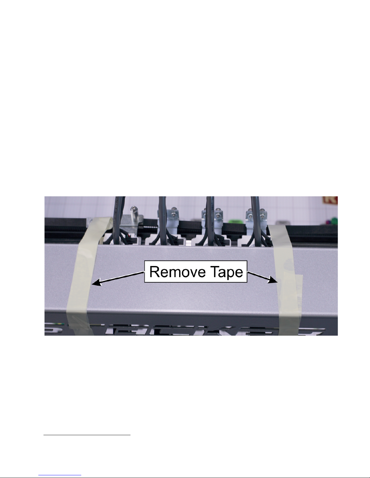
A. Remove Packaging Tape
To protect your printer during shipping, several pieces of low tack tape were attached. You MUST
remove all of this packing tape before attempting to operate the printer. You will find tape attaching
the X-gantry to the front of the printer and the USB cord has been taped to the rear of the printer.
After removing the tape, be sure to use a clean dry cloth or rubbing alcohol to remove any tape
residue.
B. Rub an oiled cloth along the linear rails.
The linears rails require a thin protective coating of oil to prevent rust and allow optimal
performance of the printer. All lubricants will eventually break down, and because of shipping, the
oil applied at the factory to your printer’s linear rails may no longer provide the necessary protection
and lubrication. Therefore, before attempting to operate the printer, we recommend rubbing an oily
rag along the linear rails to remove any rust spots and assure proper lubrication. A coating of
synthetic SAE 75W-90 gear oil was applied at the factory, but please free to use a solvent to
remove our lubrication and apply your preferred lubricant.
1
Note, do not use WD-40 as a lubricant for linear rails. WD-40 will not provide adequate lubrication.
1

STACKER S4 USER GUIDE 13
There are two Z-rails, two Y-rails, and one X-Rail. Rub an oiled cloth along all five of these linear
rails to assure they are clean and free of debris. For most users, you will likely need to wipe down
and apply some oil or grease on a monthly basis. For more information about this routine
maintenance, please refer to section 8.2.
C. Attach the Universal Filament Rail to the Rear of the Printer
Step 1. Locate the Universal Filament Rail, the two Filament Rail Brackets, and the two Filament
Rail Screws.
Step 2. Use the 3mm hex key to carefully remove two M5 x 12mm Socket Head Cap Screws from
the rear left side of the printer frame, see image below. Remove only the two screws on the left.
Remove the screws slowly! The screws are attached to swage nuts, so to avoid damaging the
swage nuts, remove the screws slowly by hand.

STACKER S4 USER GUIDE 14
Use the same two screws to attach the left filament guide rail.

STACKER S4 USER GUIDE 15
Step 3. Remove two M5 x 12mm Socket Head
Cap Screws from the rear right side of the
printer, and use these screws you just removed
to attach the Right Filament Rail Bracket.
Step 4. Place the Universal Filament Rail on the brackets and secure with the filament rail screws.
Filament rolls shown for reference.
D. Install the filament drive hardware to all four filament drives.
Step 1. Locate the filament drive idler assembly hardware. Each filament drive requires (2)
compression springs, (2) M4 x 30mm Socket Head Cap Screws, and (2) M4 Thumb nuts.
Step 2. Attach the filament drive idler assembly hardware to each of your printer’s filament drives,
as shown. The M4 thumb nuts should be flush to the end of the 30mm screws. If necessary, use
the supplied 3mm hex wrench to hold the screws while you hand tighten the thumb nuts. Note,

STACKER S4 USER GUIDE 16
Step 1. Using the 2.5mm hex driver, loosen the
two screws on the filament guide tube mounting
bracket.
Step 2. Push the filament guide tube into the
grey filament guide tube sleeve toward the hot
end to remove any slack.
there is a small amount of red anti-vibration material on each of these screws to prevent the
hardware from loosening during operation.
E. Attach the Filament Guide Tubes to all four filament drives.

STACKER S4 USER GUIDE 17
Step 3. Hold the grey sleeve with both hands as shown. While pushing and holding the tubes
together with one hand above the hotend, insert the opposite end through the filament guide tube
mounting bracket as shown. The gray sleeve will be held in position with the mounting bracket,
and the inner tube will be inserted into the fitting. The filament guide tube will descend
approximately 20mm into the fitting.
Step 4. By turning the grey filament guide tube
sleeve, you can manipulate the tube’s arc. You
want the arc to stand as tall as possible.

STACKER S4 USER GUIDE 18
Step 5. Tighten the screws on the filament
guide tube bracket to secure the grey sleeve
tube.
Step 6. Secure the hot end power cable with
one zip tie as shown. Trim the tail from the zip
tie once it has been tightened.
Step 7. Use the filament guide tube clips to
secure the wire harnesses and guide tubes
together. Use five clips per guide tube/wire
assembly.

STACKER S4 USER GUIDE 19
Step 8. Attach the filament guide tube bar by
clipping the bar at four locations to the grey
filament guide tube sleeves as shown. Note,
the location of the filament guide tube bar is
below the apex of the arc and toward the rear
of the printer to allow full movement of the
printheads. The distance from the top of the
extruder to the filament guide tube bar should
be approximately 235mm.
When attaching the blower duct,
make sure it is attached with the
proper orientation, otherwise the
blower duct will scrape on the bed.
The blower duct has a small “T”
printed on the top to help identify
the top.
F. Attach the blower fans Duct:
Your printer includes four bower fan ducts printed with colorFabb_XT CF20 filament. If you wish to
replace these ducts, you can print them with your 3D printer. Two versions of the STL file is
available on our website.
● http://stacker3d.com/stl/blower-duct-solid.stl
● http://stacker3d.com/stl/blower-duct-1mm-wall.stl

STACKER S4 USER GUIDE 20
Your printer ships with two North American 10 amp cords with
C13 connectors. This is a common “computer” type power cord
and is widely available throughout the world to fit your specific
power outlets. If you are not using North American 115V AC
power and outlets, please purchase a proper cord type at your
local electronics store or online retailer.
G. Connect Power Cords
For typical operation, the Stacker S4 should have at least one dedicated 20 Amp circuit. The power
supply is auto switching and will accept 115 to 230 volts of AC power. We have attached a data
sheet for the power supply to help you properly connect it to your power source and determine
compatibility. Please reference this data in Section 11.4.
3.3. Uninterruptible Power Supply (UPS)
We strongly advise the use of a 1000VA or greater uninterruptible power supply (UPS) with your
printer. Any sudden loss of power, no matter how brief, will likely cause the electronics in your
printer to reset, and this will ruin your print. If you want to avoid the pain and suffering associated
with losing a multi-hour print, then we recommend a UPS. Furthermore, power spikes and
brownouts can damage the printer’s electronics. Any good quality UPS will save you from
momentary power loss or brownouts and will protect your printer from potential damage. We cannot
stress enough the importance of this very inexpensive insurance. Uninterruptible power supplies
(UPS) are widely available from computer and electronics retailers.
4. Your First Test Print
After you have completed all of the assembly steps in Chapter 3, you are ready to run a test print.
Running a test print is the best method of familiarizing yourself with the printer and to confirm it is
properly calibrated. The following steps will also help teach you the basic steps used to produce a
print.
4.1. Running Your First Print
A. Download and Copy GCODE to an SD Card
In most cases, you will be creating your own GCODE by using a slicing engine such as Simplify3D,
but for this test print, we recommend using our GCODE because it should provide proven results.
To download the test print GCODE, go to http://stacker3d.com/stacker-3d-printer-support/ and
select the Stacker Emblem V2 for 050 nozzle GCODE file. If you click on the link, your web
browser will attempt to open the GCODE file within the browser, so in order to save the file to your
computer, right click on the file link and select “save link as…” to download the file to your
computer.

STACKER S4 USER GUIDE 21
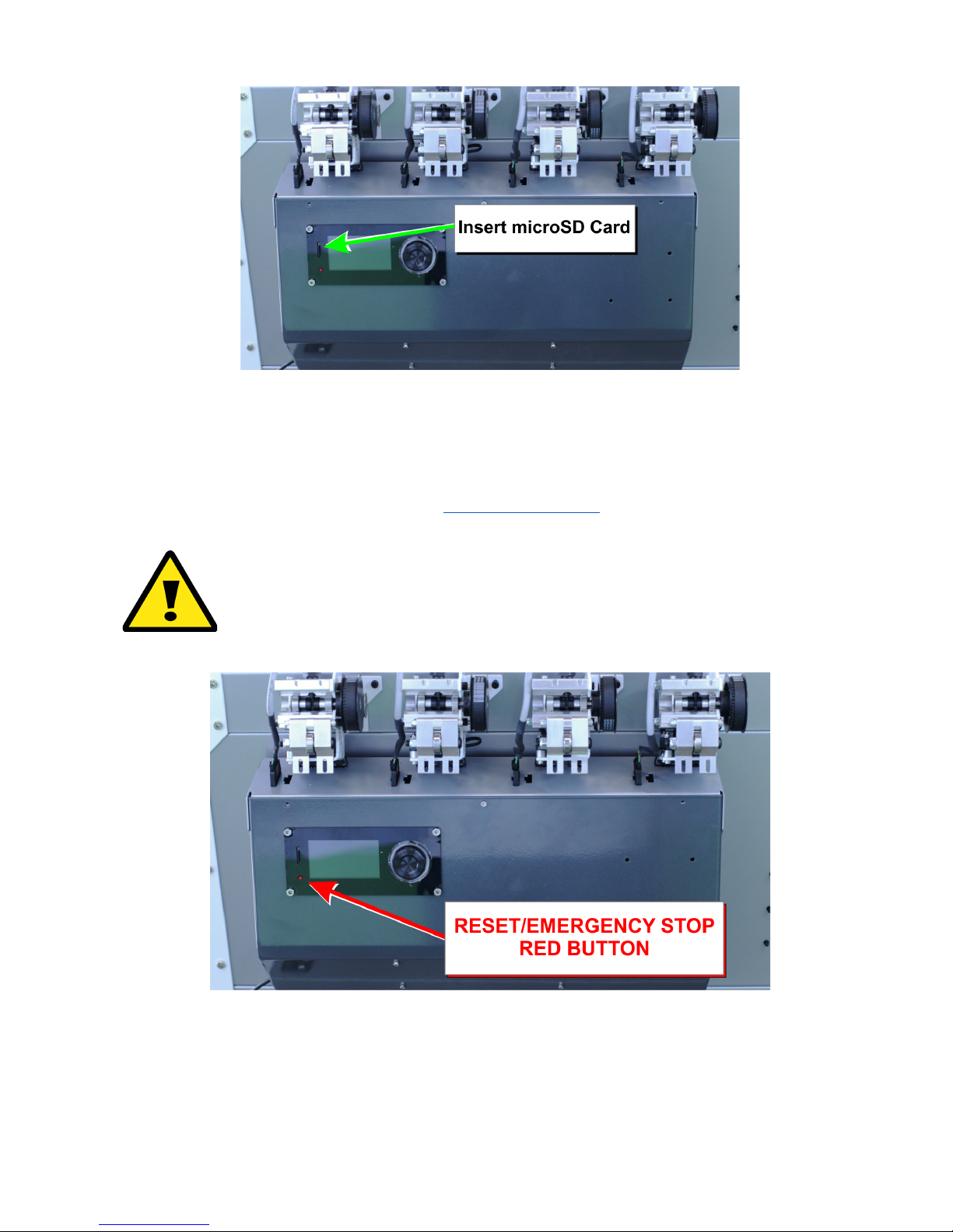
If the printer is ever behaves in a manner in which you feel the printer could
cause damage to itself or others, immediately press the Reset/Emergency
Stop button. The Reset/Emergency Stop button will disable the printer’s
motors, hot ends, and heated bed. Unplugging or turning off the printer
during operation can cause damage to the printer.
Next, transfer the downloaded GCODE file from your computer to the provided SD card. If your
computer does not have an SD card slot, you can purchase an inexpensive pocket sized SD card
reader that will work with an available USB port on your computer.
B. Power Up Printer
The Stacker S4 has two power supplies and two power switches (one for each power supply), be
sure to turn on both power switches. The printer will will not operate if only one of the power
switches is turned on.
C. Load Filament
Step 1. Load Filament Spool. Loosen and remove one of the Universal Filament Rail knobs.
Carefully lift one side of the Rail to slide the spool of filament onto the Rail. Reattach the Filament

STACKER S4 USER GUIDE 22
Rail knobs to secure the rail in place. Place the filament rolls so the filament goes over the top of
the roll as shown by the right image below.
2
Step 2. Preheat the print bed and hot end. Every filament has an optimal extruding temperature.
Please refer to Section 11.2 to see the recommended settings for a variety of filaments. In this
example, we have selected to use colorFabb PLA/PHA filament for our test print.
To preheat the bed and nozzle, begin by depressing the knob next to the LCD panel to open the
LCD menu. Next, turn the knob to highlight Extruder, then push the knob to enter the Extruder
sub-menu.
From the Extruder sub-menu, select Bed temp. Once selected, you can dial the temperature to
where you want it, then push the dial to set the temperature and the printer will immediately begin to
warm the bed to the temperature you requested. In our example, we have call for a bed
temperature of 50°C.
Next, in the same way you adjusted the bed temp, dial the knob and set the temperature for Temp.
1 which sets the nozzle temperature for the first extruder. In our example below, we have called for
2
Note, filament is shown as an example and is included with your printer.

STACKER S4 USER GUIDE 23
a temperature to 220°C. Note, the current temperature of the hot end in the image below is 34.3°C
and rising to 220°C
Step 3. Insert the filament. With the filament drive idler assembly open, insert and push the
filament upward by hand through the small hole beneath the filament gear then continue upward
past the gear and through the filament guide just above the gear.
Please note, if filament has already been installed and you wish to remove it. You must wait for the
hot end to reach the appropriate temperature to melt the filament before you will be able to pull the
filament by hand and remove it from the nozzle, filament guide tube, and extruder.
Step 4. Extrude filament by hand. When extruder 1 has reached the temperature needed for your
filament, you will be able to prime the nozzle by gently pushing the filament by hand through the
filament guide tube. Note, if extruder 1 has not reached the temperature required to melt the
filament, it will be difficult (if not impossible) to push the filament through the nozzle.
By pushing a small amount of filament by hand through the nozzle, you will know that the nozzle is
primed and ready to print. Please note, when you initially extrude by hand, you may see a color of
filament extruded from the nozzle which does not match the filament you are using. Do not be

STACKER S4 USER GUIDE 24
alarmed. You are seeing the remnants of the PLA filament used during your printer’s initial
calibration and testing at Stacker.
Step 5. Secure the Filament Idler Assembly. To close the Idler Assembly, lock the two heads of
the screws into the Filament Idler Assembly.
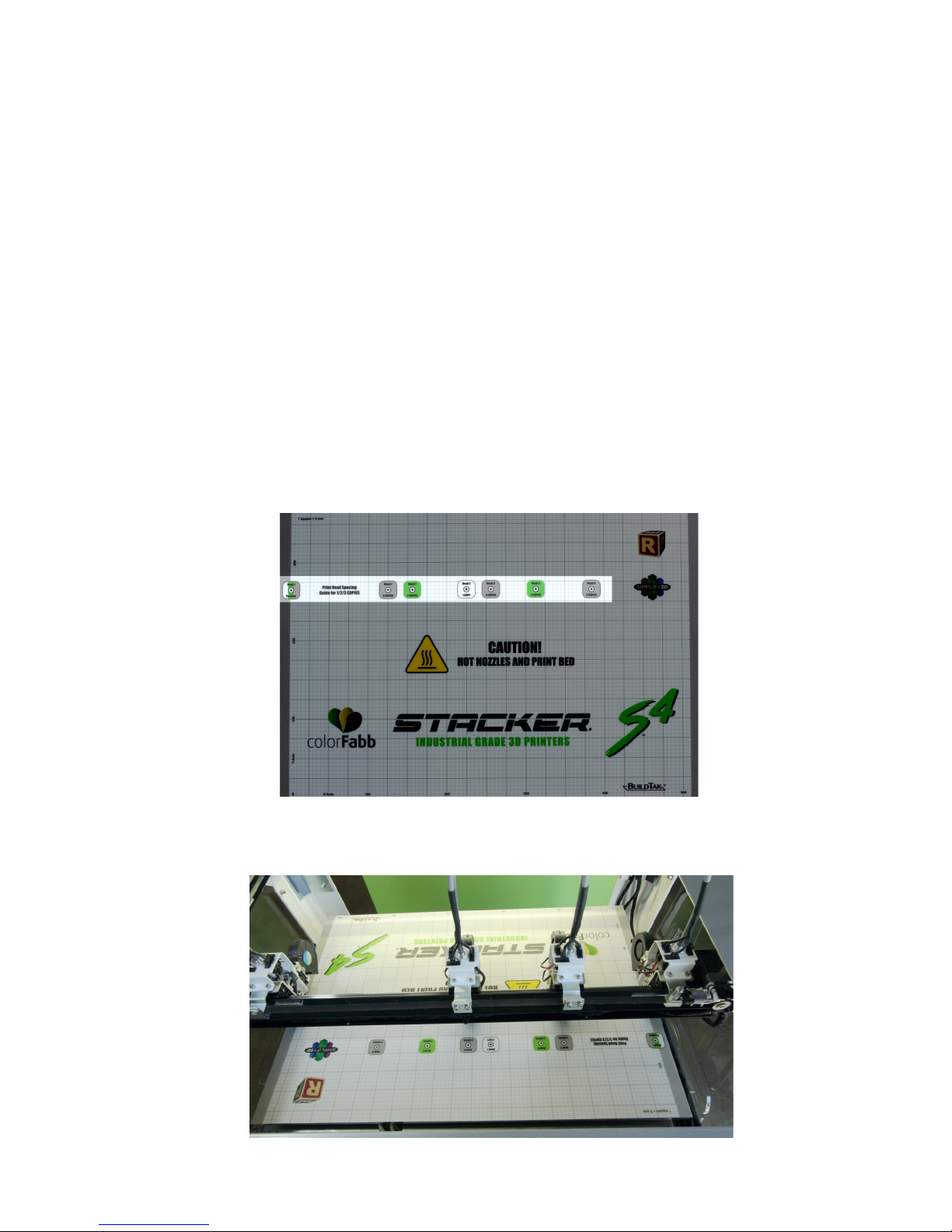
D. FINAL CHECK! Make Sure the Print Bed is Clear and Heads are Properly Positioned to
Start your Print

STACKER S4 USER GUIDE 25
You should always double check your print bed to confirm that it is clear
of tools and printed objects before starting a print.
Stacker performed a test print at our factory. This test print may still be on the bed, so you need to
remove it before performing your test print.
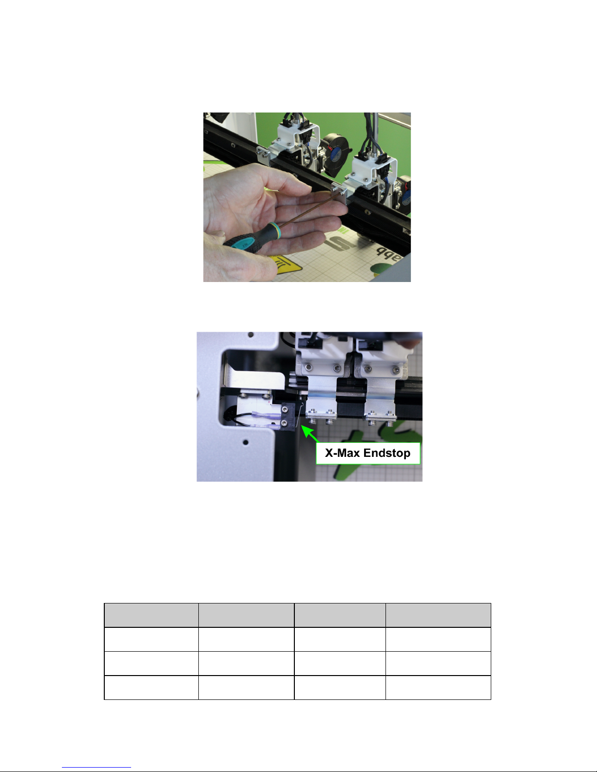
With your first print, you will only be using one printhead, so it is best practice to slide the three
unused heads to the right side of the gantry away from the printing head. Important, you do not
want the unused heads to trip the X-Max End Stop. If you trip the X-Max End Stop, your printer
will think it has reached the edge of the bed at the beginning of the print, and it will only print a
single line of filament along the left edge of the print bed. Be careful to avoid tripping the X-Max
End Stop with unused heads.
Note, the Guard Plate has been removed to show the endstop, do not operate your printer without
the guard plate in place.
E. Insert the SD Card and Select the File
To start your print, insert the microSD card into the controller. Whenever an SD card is inserted, a
menu of available files will appear on the LCD. Turn and depress the knob to select the GCODE
file you wish to print. Once the knob has been pressed, the selected GCODE file will begin to run
as soon as the bed and nozzles have reach the temperatures specified by the GCODE file.
STACKER S4 USER GUIDE 26
If something seems seriously wrong with the printer, such
as the nozzles crashing or scraping on the bed, you should
immediately press Reset/Emergency Stop button.
F. Watch your Test Print
While your first print is running, watch for any problems with the printer. Although the printer was
calibrated prior to shipping, calibration can sometimes be thrown off during shipping. If the printer is
not performing adequately, calibration may be necessary to improve print quality. For calibration
instructions turn Chapter 6. Please contact info@stacker3d.com if you have any questions.
G. Removing your Test Print from the Print Bed
It is sometimes difficult to remove a printed object from the BuildTak. If you allow the bed to fully
cool, it can sometimes make print removal easier. Also, using the BuildTak Spatula (sold
separately) is a very useful tool which allows you to pry your parts from the build plate.

STACKER S4 USER GUIDE 27
Another option for part removal is the BuildTak FlexPlate, p/n 90-109. The FlexPlate is a removable
build plate which enables you to literally “pop” your parts off the BuildTak. Please check our
website for availability.
4.2. Turning Off the Printer
When turning off your printer, wait for the cooling fans to fully cool your extruders before
turning off the printer. You can observe the temperatures of your extruders on the LCD. Turning
off the printer with hot extruders can damage your printer. Proper cooling is necessary to prolong
the life of your hot ends. We recommend allowing hot ends to cool below 50°C before turning off
the power to the printer.
4.3. Troubleshooting Poor Quality Prints
If your print quality is less than desired, please take a look at the Simplify3D print quality
troubleshooting guide. This User Guide provides excellent visuals of common problems and
solutions.
● https://www.simplify3d.com/support/print-quality-troubleshooting/
If your print failed, please go through the printer calibration steps in chapter 6, and contact Stacker
for help at info@stacker3d.com.

STACKER S4 USER GUIDE 28
Step 1. Remove the filament from your
hotend. From the LCD controller, depress the
knob to open the menu, then turn and depress
the knob to select Extruder.
From the Extruder sub-menu, set the
temperature for the nozzles you will be
removing. The temperature should be the
same as the type of filament which is in the
nozzle. In our example, we are changing
nozzles on head 1, so we have set the
temperature for extruder 1 to 220°C because
we have been using PLA/PHA with our nozzles.
5. Changing Nozzles, Filament Guide Tubes, and BuildTak
Your Stacker printer comes with four 0.50mm mid temp nozzles pre-installed. The 0.50mm nozzles
provide a good balance between printing speed and detail. Nonetheless, we recommend
experimenting with different nozzle sizes because changing your nozzle size can increase print
speeds (with larger nozzle sizes) or improve the fine detail of your prints (with smaller nozzle sizes).
A variety of nozzles are available from our website http://stacker3d.com/product/3d-printer-nozzles/.
Although nozzles and filament guide tubes can last for hundreds of hours of operation, both the
nozzles and filament guide tubes are wear parts which will eventually need to be replaced to
maintain optimal printing performance.
The following steps will instruct you on how to properly remove and install new nozzles and filament
guide tubes. Please follow these steps VERY CAREFULLY. Improper installation of nozzles or
filament guide tubes will result in poor quality prints and filament jams.
5.1. Removing Nozzles

STACKER S4 USER GUIDE 29
When the nozzle is hot, release the filament
drive idler assembly and pull out the filament by
hand. Remove the filament completely from
the filament guide tube by hand by pulling the
filament out of the guide tube.
Note: Whenever you return filament to a spool,
avoid filament crossover by pushing the end
of the filament through one of the side holes on
the filament spool. Filament crossover will
prevent the filament from feeding and cause
the printer to jam.
Step 2. Clean up any filament around the tip of the nozzle. While the nozzle is hot, you will be
able to wipe the warm filament from the nozzle and underneath heater block. Use a dry cotton cloth
and wipe the tip of the nozzle and underside of the heater block to remove any filament. NOTE,
THE NOZZLE IS HOT! PROTECT YOURSELF FROM GETTING BURNED! You will want to
thoroughly remove all the filament from underneath the hot end. If you fail to remove all of the
filament, you may experience difficulty removing the heater block in Step 6.
After the nozzle and heater block are clean, TURN OFF THE EXTRUDER and wait for it to cool.
Pressing the Reset/Emergency Stop button will turn off all of the extruders.

STACKER S4 USER GUIDE 30
IMPORTANT: Turn off the heat and wait until the hot end has cooled down
before proceeding with the next step!
Step 3. Remove the Filament Guide Tube Clips and Filament Guide Tube Support Bar. Detach
the filament guide tube clips and the filament guide tube support bar from the grey filament guide
tube sleeve.
Step 4. Remove the Filament Guide Tube from the Filament Drive. Loosen the filament guide
tube support bracket, and then depress the push-fit type fitting with your finger while pulling the
filament guide tube up and out of the fitting. Once the filament guide tube is removed from the
fitting, slide the grey filament guide tube sleeve off the filament guide tube and set it aside.

STACKER S4 USER GUIDE 31
Step 5. Remove the filament guide tube
from the nozzle. Use the supplied nozzle
wrench to release the grip on the push-type
fitting on the top of the hot end heat sink. With
the fitting compressed, gently pull up on the
filament guide tube until it releases from the
nozzle. Pull the tube all the way out and set it
aside.
Step 5a. What to do if your tube is stuck. If
the guide tube is stuck into the nozzle you must
remove the nozzle and guide tube
TOGETHER. Continue following steps with the
guide tube inside the nozzle. In a later step
you will be instructed to use a pliers to remove
the filament guide tube from the nozzle.
Step 6. Remove the heater block assembly.
First disconnect the electrical connector with
your fingernail by pressing down on the tab and
sliding off the connector. DO NOT USE A
PLIERS because pliers can easily damage
these small plastic connectors.
Next, using a 1.5mm hex wrench, loosen the
two heater block screws on the right side of the
block. These screws hold the block to the
nozzle. Once loosened, the heater block
should slide off the nozzle. If the heater block
will not slide down, then loosen the two screws
a little more until the heater block is free. Be
careful not to drop the heater block because
dropping the block can cause damage to
heater block’s electronics.

STACKER S4 USER GUIDE 32
Step 7. Remove the nozzle. To loosen the nozzle from the heat sink, use the supplied nozzle
wrench or a 5mm wrench to turn the nozzle counterclockwise. Once you loosen the nozzle with the
wrench, you can turn with your fingers unit it is removed.
Step 7a. Removing the nozzle when the Filament Guide Tube is stuck. If the filament guide
tube is still connected to the nozzle because it was stuck (from Step 5a), no worries. Just let the
tube rotate along with the nozzle as you unscrew it with the wrench. Once the nozzle is removed,
twist and turn the guide tube until it can be removed from the nozzle. You may need to use a pliers
to remove the filament guide tube if it is stuck in the nozzle.
SPECIAL NOTE ON FILAMENT GUIDE TUBES. After many hours of use at high temperatures the
filament guide tubes may degrade and get stuck inside the nozzle. If you are unable to remove the
filament guide tubes by hand, use a pliers. If the tube is damaged during removal, then trim the
damaged portion above the point where you gripped it with the pliers. You can usually trim the end
of the tube once or twice before the tube becomes too short for use. We recommend trimming the
end of your tube with a sharp knife at a 90° angle to ensure the end of the tube properly seals within
the nozzle. Make absolutely sure your trim cut is perfectly square. When in doubt, purchase a new
Filament Guide Tube.
5.2. Installing Nozzles
Step 1. Screw the nozzle into the heat sink by hand until it is fully seated. When the nozzle is
finger tight, reverse (and loosen) the nozzle ONE-AND-THREE-QUARTER REVOLUTIONS.
Step 2. Insert the filament guide tube. Check the end of the filament guide tube to be sure it is
cut square and in good condition. If the the tube is not in perfect condition, trim the damaged
portion of the tube with a sharp knife. Install the filament guide tube, and push it all the way into the
nozzle. Make sure the filament guide tube is seated at the bottom of the nozzle! If the guide tube is
not seated within the nozzle, problems can occur with filament extrusion.

STACKER S4 USER GUIDE 33
Step 3. Tighten the nozzle. Use your finger to tighten the nozzle, then use the nozzle wrench to
turn and secure the nozzle. DO NOT OVERTIGHTEN! Just turn the nozzle till it is snug. With the
nozzle snug, look at the filament guide tube to see that the push-type fitting was lifted by the
filament guide tube.
Finally, test for “play” in the filament guide tube system. Take the filament guide tube with your
fingers and pull up and push down. While you push and pull, make sure there is no movement in

STACKER S4 USER GUIDE 34
Step 4. Replace the filament guide tube
sleeve. When the filament guide tube is
attached to the hot end and there is no “play” in
the system, return the grey Filament Guide
Tube Sleeve onto the filament guide tube.
Step 5. Push the filament guide tube into the
grey filament guide tube sleeve toward the hot
end to remove any slack.
Step 6. Hold the grey sleeve with both hands as shown. While pushing and holding the tubes
together with one hand above the hotend, insert the opposite end through the filament guide tube
mounting bracket as shown. The gray sleeve will be held in position with the mounting bracket,
the tube. If the tube and fitting moves up and down, even a little bit, remove the nozzle and go back
to Step 1 and carefully redo each step again.

STACKER S4 USER GUIDE 35
and the inner tube will be inserted into the fitting. The filament guide tube will descend
approximately 20mm into the fitting.
Step 7. By turning the grey filament guide tube
sleeve, you can manipulate the tube’s arc. You
want the arc to stand as tall as possible.
Step 8. Once turned to the correct position,
tighten the screws on the filament guide tube
bracket to secure the grey sleeve tube in place.

STACKER S4 USER GUIDE 36
Step 9. Reattach the filament guide tube clips
and to secure the wire harnesses and guide
tubes together, then attach the filament guide
tube support bar.
5.3. Replacing BuildTak
Your print bed is covered by a thin, durable plastic sheet of BuildTak that adheres to the aluminum
bed. If treated with care, this BuildTak sheet can last for a very long time, but when parts are hastily
scrapped from the build surface, it is possible to damage your BuildTak. Furthermore, the BuildTak
surface will gradually become less reliable over time with heavy use in the same locations. Shifting
the position of parts in your GCODE can reduce the wear upon your BuildTak.
If you wish to clean the BuildTak surface, wipe it down with isopropyl rubbing alcohol. DO NOT use
acetone because acetone will destroy the BuildTak.
Custom BuildTak sheets for Stacker 3D printers are available at www.stacker3d.com.

To replace a sheet of BuildTak,
1. Heat the bed to 50°C.
2. Peel the old worn sheet of BuildTak from the bed.
3. Use isopropyl rubbing alcohol and a clean cloth to wipe the aluminum bed clean.
4. Carefully peel the backing from the new BuildTak sheet.
5. Starting at the front edge of the bed, slowly attach the new sheet while using a
plastic paint scraper to flatten the sheet and remove any air bubbles. Working slowly
and methodically will ultimately provide the best and flattest printing surface.
STACKER S4 USER GUIDE 37

STACKER S4 USER GUIDE 38
6. Printer Calibration
To assist with printer calibration, it is helpful to download and install
Stacker RUN software which is available for free on our website.
● http://stacker3d.com/stacker-3d-printer-support/
Stacker RUN software is an enhanced version of Repetier Host
customized for using Stacker printers. Most of the installation and
documentation available from the Repetier website is applicable. To familiarize yourself with
Repetier Host
● https://www.repetier.com/#documantation
Before attempting to use Stacker RUN, make sure you do not have any other software running
on your computer. If Simplify3D is open, you may be unable to connect to your printer with
Stacker RUN. Turn on the printer and open Stacker RUN. Connect the USB cable between your
computer and the printer. If the USB cable is not connected to your printer, please see chapter 11.1
for instructions on how to install the USB cable.
When all other software has been closed on your computer, click the Connect button located in the
upper left corner of Stacker RUN. A drop down menu will allow you to select the four head model.
, please visit their website.
With some computers, you may need to go into the Printer Settings menu of Stacker RUN and
change the Port setting from Auto to an available COM port. Also note, the Baud Rate should read
250000. In rare cases, some computers seem to have lackluster USB to Serial Bridge
communication. If you are having trouble connecting, even after (1) making sure the printer’s power
is on, (2) making sure the USB cables are connected properly, (3) restarting the computer, and (4)
specifying a specific COM port number within Stacker RUN, then we recommend trying Stacker
RUN with a different computer.

STACKER S4 USER GUIDE 39
When your printer is connected to Stacker RUN, you are ready to calibrate.
6.1. Adjusting First Layer Height
First layer height is critically important to 3D printing. When the printer is calibrated correctly, the
first layer has a perfect amount of “squish”. If your nozzle is too far away from the print bed, the
filament will not adhere properly, and if the nozzle is too close to the print bed, the filament will be
unable to come out of the nozzle and this will inevitably result in the filament stripping out on the
drive gear. Therefore, you want to set all the nozzles at the perfect height.
Although you can alter the layer height in your slicing software, it is always best practice to have
your printer’s actual (mechanical) layer height set perfectly.
Before making any adjustments to your printer, you should first check the gap between the nozzle
and bed with the 0.007”/0.18mm feeler gauge. When sliding the feeler gauge between the nozzle
tip and the bed, you should feel a small amount of friction from the nozzle tip. If there is no friction,
then the nozzle is too high, and if you are unable to slip the gauge between the nozzle and the bed,
then the nozzle is too close to the bed. Be aware that heating the bed will make a difference in the
gap between the nozzle and the bed, so for a more precise test, you should heat the bed to the
temperature you will be using for your print.
When confirming the gap between the bed and nozzle, all four nozzles should have the same gap.
By sliding the feeler gauge between each nozzle and the bed, the friction you feel should be very
similar. If you notice inconsistency in the gaps when comparing nozzles, you might need to perform
some advanced calibration (see section 10.1 and 10.2) to make sure all of the nozzles have equal
gaps. .
The nozzle gap is changed by turning the Z-height adjustment screw with a 2.5mm hex wrench.
Turning the screw clockwise (making the screw go upward) will LOWER the bed upon rehoming the
Z-axis (increase first layer height). Turning the knob counterclockwise will RAISE the bed into the
nozzles upon rehoming the Z-axis (decreasing first layer height). Each full rotation of the Z-height

STACKER S4 USER GUIDE 40
adjustment screw will change the layer height by ±0.2756”/0.7mm, so making quarter-turn
adjustments is often sufficient to make noticeable changes in the first layer height.
After making any change to the Z-height adjustment screw, you will need to re-home the Z-Axis with
either Stacker RUN or the LCD controller (►Main Menu » Position ►Home Z) and then test the
nozzle gap again. It is good practice to move the gantry all the way forward on the printer, so the
nozzles cannot crash into the bed if you have adjusted the Z-height incorrectly. Keep in mind, it
may take multiple attempts at turning the Z-height adjustment screw before you determine the
perfect position.
6.2. Volumetric Calibration
One secret to accurate prints and beautiful surface finish is proper volumetric flow control. Stacker
3D printers use four variables to control volume: (A) filament diameter, (B) filament drive E-STEPS,
(C) nozzle size, and (E) extrusion multiplier. Slicing engines use these variables to determine
exactly how much filament to extrude. Therefore, it is essential to set these variables carefully and
accurately for the best quality prints.
A. Filament Diameter
Stacker printers use 1.75mm diameter filament. It is very important to use filament with a highly
consistent diameter. A reason why Stacker sells and recommends colorFabb filaments is because
colorFabb uses highly advanced laser tools for precise diametric measurements, as well as a host
of other controls to ensure consistent filament diameters.
Regardless of what filament brand you use, always confirm consistent filament diameter with a
digital caliper. Measure the diameter of your filament in few different places to see if it is consistent.
If the diameter is not consistent, return the filament from where you purchased it. Filament with an
inconsistent diameter will inevitably provide inconsistent results and filament jams.

STACKER S4 USER GUIDE 41
Step 2. Clean the Drive Gear. Release the
filament drive idler bearing assembly and
remove any filament from the filament drive.
Look closely at the drive gear with a bright
flashlight. Turn the gear manually and inspect
it for filament debris. If the drive gear is dirty,
you will not get an accurate measurement
during calibration. Use the filament drive
cleaning brush to be sure the gear is clear of
any filament debris. When the gear is
completely clean, you are ready for the next
step.
Step 3. Insert the Filament: Insert the filament
upward through the small hole beneath the
filament gear, then push the filament upward
past the gear and through the filament guide
just above the gear. To avoid wasting filament
during this measuring process, you do not need
to push the filament all the way to the extruder.
Push the filament so it has just entered the
filament guide tube and then reattach the idler
bearing assembly. Note, you have preheated
your extruders just in case the filament is
advanced to the hot ends during this test.
B. Test Filament Drive E-STEPS
Calibrating your filament drive E-STEPS (extruder steps
) is essential to achieving the best quality
prints, and it should be done every time you change filament types or brands.
The calibration process only takes a few minutes and does not require you to waste filament. The
only tools you will need is the filament guide cleaning brush, a metric ruler, a calculator, and an ink
pen for marking the filament.
Step 1. Preheat the Extruder. Preheat your extruder to the filament’s required temperature.

STACKER S4 USER GUIDE 42
Step 4. Mark 120mm of filament: With a pen
and ruler, mark the filament at 120mm.
Step 5. Extrude 100mm of Filament: Open
Stacker RUN, connect to your printer, and use
the Manual Control tab to extrude exactly
100mm of filament.

STACKER S4 USER GUIDE 43
After attempting to extrude 100mm, measure to
see what was actually extruded and write down
the number. Because you marked 120mm and
extruded 100mm, your mark should show
20mm of filament. In other words, you
extruded 100mm of filament, so you should
have 20mm of filament remaining. In the image
to the right, we extruded 115mm of filament
because we only measure 5mm of filament.
For example, I attempted to extrude 100mm of filament but the printer actually extruded 115mm
of filament, so I would get the following result:
100 ÷ 115 = 0.869565
Because my current “steps per mm” in the EEPROM is set to 255, I would do the following:
0.869565 x 255 = 221.739
Step 6. Open your EEPROM window in Stacker RUN by pressing Alt+E or select “Firmware
EEPROM Configuration” under the Config menu to see your current E-STEPS for each extruder.
To calculate the new E-STEPS number, use this formula:
( 100mm ÷ Your Measurement ) x ( Your current E-Steps ) = Your New E-Steps

STACKER S4 USER GUIDE 44
Thus, in this example, I should change the “steps per mm” from 255 to 221.739.
Step 7. Enter your new E-Steps for your extruder, but before you start printing, be sure to confirm
these results. Go back and repeat steps 4 through 6 again to confirm your E-Steps setting.
C. Verify Nozzle Size
Stacker nozzles use a system of small machined dots around the tip for identification purposes. Be
sure to enter the correct nozzle size in your slicing software. Stacker’s standard nozzle size is
0.5mm, also called a 050 nozzle, and these were pre-installed on your printer.
A Note about Stacker’s MID and HIGH temp nozzles: For most filaments and
applications, it is best to use our MID temp nozzles. Our HIGH temp nozzles are only
necessary when using filaments which require temperatures between 275°C and 300°C.
HIGH temp nozzles are identified by a special machined “band” to distinguish them from our
MID temp nozzles.
D. Extrusion Multiplier
For even finer volumetric calibration you can adjust the extrusion multiplier in your slicing engine.
Most filaments will print very accurately with a 100% extrusion multiplier setting in your slicing
engine. Nevertheless, some filaments like XT-CF20 Carbon Fiber filament will over extrude due to
die swell, and will therefore require a lower extrusion multiplier, often a multiplier of 0.95 is sufficient
to compensate for die swell, but sometimes a multiplier as low as 0.88 is necessary. Printing a
simple single wall test cube will allow you to verify the accuracy of your print widths.

STACKER S4 USER GUIDE 45
6.3. PID Calibration
The PID controller on your printer continuously adjusts the power sent to the hot ends and heat bed
in an effort to maintain efficient and consistent temperatures. When the PID settings are incorrect,
the temperature changes of your bed and hot ends can affect your prints. Variations in nozzle
temperatures over a short time may not seem like a problem, but in extreme cases, wide
temperature variations during operation can cause stringing, blobs, or even clogged nozzles. To
best control temperatures, you should run a PID autotune on each of your nozzles. Whenever you
change a heater block, you should always perform a PID autotune and make the necessary
changes to your EEPROM.
To run a PID autotune, you will need to open Stacker RUN and enter the flowing text into the
manual control line.
M303 e0 s240
We should explain that command: M303 is the GCODE command to run a PID Autotune. The “e” is
referring to the extruder number; whereby, e0 = head 1, e1 = head 2, e2 = head 3, and e3 = head 4.
The “s” is setting the temperature, 240°C in our case. Therefore if you were going to run a PID
Autotune on head 2 at 240°C, you would type the following line into Stacker RUN:
M303 e1 s240
Whenever you run PID Autotune from Stacker RUN, you want the heaters to start at room
temperature!
will be invalid.
When Stacker RUN has completed the PID Autotune, you will see three sets of PID numbers with
the letters “Kp”, “Ki”, and “Kd”. Always use the first set of “p”, “i”, and “d” numbers. Enter these
numbers into your EEPROM for the corresponding nozzle you test.
Classic PID
Kp: 8.94
Ki: 0.51
Kd: 20.00
If you are calibrating all four nozzles, then you will need to run the PID autotune four times -- once
for each head.
If the heater blocks begin at a temperature other than “cold
”, then your PID results
STACKER S4 USER GUIDE 46
7. Multi-Head Printing
The Stacker S4 has four printheads, and these heads can be used to print the same part in different
materials, at the same time. When printing copies of the same part, this is called multi-part print
mode
. When using a certain number of printheads to print one part with different materials, it is
called multi-material print mode
7.1. Multi-part Print Mode
With Stacker’s multi-part print mode, each extruder can print a copy of whatever is being printed by
the first extruder. In other words, selected extruders will duplicate (copy) the movements of the first
extruder. Because the S4 has four heads, you are able to print up to four copies in multi-part print
mode.
Step 1. Spacing and Securing the Extruder Heads. In multi-part print mode, each of your heads
will operate on only a portion of the print bed. You must space your printheads apart at specific
distances along the X gantry depending upon the number of printheads you will be using. Use the
“Print Head Spacing Guide for 2/3/4 Copies” on the print bed to determine the locations of the
heads you will be using.
.
For example, if you were printing three copies, then you will be using three heads, and they would
be positioned in the locations shown below.
STACKER S4 USER GUIDE 47
Print Mode
Area (X-Axis)
Area (Y-Axis)
Area (Z-Axis)
No Copies
380
365
625
1 Copy
220
365
625
2 Copies
150
365
625
Once the heads have been positioned along the gantry where indicated by the guide, secure the
heads by pushing the belt clamp bracket upward with your finger and and securing it with the
2.5mm hex driver. Once tightened, make sure it is secure by moving head one. When head one
moves, all of the secured heads should move together along the X-gantry in tandem.
It is best practice to slide the unused heads to the right side of the gantry away from the printing
heads. Be careful to avoid tripping the X-Max End Stop with unused heads.
Step 2. Set Extrusion Mode. To set the number of printheads you will be using in multi-part print
mode
, use the LCD to set the number of copies you wish to print. ►Main Menu » Extruder » (■ 1
Copy/■ 2 Copies/■ 3 Copies).
Be aware that when you are printing in multi-part mode
changes depending upon the number of printheads you are using in multi-part mode
, the total build volume available on the bed
.

STACKER S4 USER GUIDE 48
3 Copies
120
365
625
When using multi-part printing, it is a good idea to adjust the bed size in your preferred slicing
engine, so you see the actual space available for part placement.
Step 3. Run your print. If the spacing is correct, you will be able to print multiple copies of the
same parts.
7.2. Multi-material Print Mode
Printing in multi-material mode is for advanced users and requires a good understanding of the
operation of your Stacker printer and Simplify3D. Multi-material printing involves a critical process
of calibration, and if calibration is not performed correctly, the results will be imperfect. Before
attempting multi-material
printing, Stacker recommends viewing the Simplify3D tutorials to learn the
basics about slicing your objects for multi-material printing.
Because the calibration process for multi-material printing is time consuming, we recommend you
record your settings. In the future, when you switch between multi-material printing and normal
printing, you will be able to easily enter your previous settings into the EEPROM of StackerRUN to
speed the calibration process.
A. Dual Color Prints (2 Head Printing)
Step 1. Set the X Offset for Extruder 2. To begin, remove heads three and four from the X rail
(see section 7.3 for hot end removal instructions). Position head two approximately 150mm from
head one and attach head two to the belt. With head two secured to the belt, use a caliper to
measure the exact distance between the nozzle tip of head one and the nozzle tip of head two.
Connect the printer to StackerRUN and open the EEPROM to enter the offsets. Note, StackerRUN
uses steps per millimeter rather than millimeters, so you must multiply your offset distance

STACKER S4 USER GUIDE 49
measurement by the number of X-axis steps per mm to get the distance in steps for the Extr.2
X-Offset.
For example, if your X-axis steps per mm is 146.1, then you would multiply 146.1 by the
exact distance you measured between the two nozzle tips. Thus, if the nozzle tips were
151mm apart, then 146.1 x 151 = 22,061.10 steps.
Enter the resulting number of steps into the Extr.2 X-offset in the EEPROM. The offset in the
EEPROM will be your starting point, and you will make fine adjustments to this setting using the
LCD after you perform a test print.
Step 2. Prepare your Print in Simplify3D. The Dual Extrusion Wizard in Simplify3D is a useful tool
to prepare your model for printing with two heads. Be sure to view the tutorials on the Simplify3D
website to better understand how to use this wizard. The bullet points below are essential
components for successful two head prints:
● When placing the model, be sure to position it to the far left side of the bed. The
model will automatically reposition to accommodate for the offset, so you want the
model placed as fart to the left as possible.
● You will need to bring in two models for dual color prints. Use the Dual Extrusion
Wizard to align models and establish a grouped process.
● If you are printing with support structures, then be sure to only have the model that
gets support selected and manually place the supports.
● Assign ONLY the ooze shield to extruder 1 and ONLY the wipe and prime tower to
extruder 2.
Step 3. Perform a Test Print. It is best to perform a simple test print to precisely calibrate the X
and Y offsets. We recommend printing a simple dual color calibration object such as the “Dual
Extruder Calibration Print” (http://www.thingiverse.com/thing:533814). Looking at a simple
calibration print and measuring the offset error with a calipers enables you to make small
adjustments to the X and Y offsets.
To make these small adjustments to the X and Y offsets use the LCD controller. Select ►Main
Menu » Configuration » Extruder » Select extr. 2 » X-offset (or Y-offset). Enter the distance for
the offset in mm.
For example, on the test print below, you can see that the silver filament is 0.75mm to the left of
where it should have been printing, so we need to add 0.75mm to the X-offset.

STACKER S4 USER GUIDE 50
Number of Print Heads
on X-Rail
Maximum X travel
distance of head 1
4
3
2
1
390mm
430mm
470mm
510mm
You may need to reprint the test print several times to precisely dial in the settings. Once your X
and Y offsets have been precisely calibrated, you are ready to slice and print your object.
B. Three Color, Four Color, or Multi-material Prints (3 or 4 Head Printing)
The process of calibrating the printer for using three or four heads is nearly an identical process to
dual color printing. Because of the limited travel distance available on the X-rail, you should
position your heads together as a group depending upon the size of the object you are printing.
Because the nozzles are approximately 40mm apart, the expected offsets would be 40mm for
Extruder 2, 80mm for Extruder 3, and 120mm for Extruder 4. Of course, printing a simple
calibration print will help with fine tuning these offsets.
Unfortunately, having the heads positioned together as a group can cause scarring and oozing of
filament on your print, but careful slicing and placement of custom wipe and prime towers can
alleviate many of these problems.
7.3. Removing Print Heads
Depending upon the number of print heads used for a print, any unused hot ends on the X-rail will
reduce the total available print area along the X axis. Each hot end attached to the X-rail reduces
the total available movement by approximately 40mm. Therefore, removing unused hot ends from
the the X-rail will increase the maximum available print area.
On the Stacker S4, you can remove the second, third, and fourth hot ends fairly easily. The first hot
end should never be removed from the printer.

STACKER S4 USER GUIDE 51
Whenever removing hot ends, it is critical that the electrical connections are not detached. If the
wires are disconnected from the hot end, the printer will go into an error state.
When removing one or more hot ends, please follow these steps:
Step 1. Make sure the hot ends are turned off. Confirm that your hot ends are at room
temperature to avoid injuring yourself or damaging the printer. If your hot ends are not at room
temperature, reduce the temperature and wait for them to cool before attempting to detach the hot
end from the X rail.
Step 2. Remove Guard Plate. On the printer frame, use a 2.5mm hex driver to remove the two M3
x 6mm screws and lock washers holding the guard plate in place.
Step 3. Remove Belt Clamp Bracket. On the rear of the hot end, use a 2.5mm hex driver to
remove the two M3 x 8mm screws attaching the belt clamp bracket. After the screws are removed,
slide the belt clamp bracket from the hot end.

STACKER S4 USER GUIDE 52
Step 4. Carefully slide the hot end from the linear rail. Using the space opened by removing the
guard plate, carefully and slowly slide the hot end to the right to remove it from the linear rail.
BE CAREFUL! Whenever a hot end is removed is removed from the rail, you
must handle it very carefully. The linear block which attaches to the linear
rail uses tiny recirculating ball bearings for movement, and if any of these
ball bearings fall out of the block, it will lead to catastrophic failure of the
movement system. Always handle the hot ends carefully to prevent any
damage to the linear blocks!
Step 5. Carefully Handle and Store the Removed Hot Ends. Because the electrical wires must
remain attached to the printer, it is best to attach the hot end directly to the printer. Ideally, the hot
ends should be attached to our Hot End Storage Rail (p/n 50-052).
3
3
The Hot End Storage Rail (p/n 50-052) is sold separately.

STACKER S4 USER GUIDE 53
Step 6. Reattach the Guard Plate. After the heads have been removed and stored carefully,
reattach the guard plate that was removed in Step 1.

STACKER S4 USER GUIDE 54
8. Basic Printer Maintenance
Other than periodically replacing nozzles, filament guide tubes, and BuildTak as needed, the basic
maintenance required on a Stacker 3D printer is minimal.
8.1. Keep Your Printer Clean
Inevitably, from regular use, small bits of filament debris will land on your printer. You must
periodically remove this filament debris to protect your printer from damage. The combination of
blower fans and small bits of filament can result in debris landing upon the moving parts of your
printer. Clean filament debris to prevent damage to your printer’s moving parts.
8.2. Linear Guides
The linear rail system on the S4 uses recirculating linear bearings and profile rail guides. For
optimal performance, lubrication of these parts is essential. Lubrication promotes smooth
operation, minimizes friction and wear along the raceways, dissipates heat, and prevents corrosion.
The absence of proper lubrication will eventually lead to machine failure.
The frequency with which you will need to re-apply lubricant to your linear rail system will largely
depend upon use and environmental conditions. More humid environments will generally require
more frequent re-application of lubricant to protect the printer’s raceways from rust.
Z Rails: To lubricate the vertical Z rails, use Mobil 1™ Synthetic Grease. Lightly apply the
grease to the entire rail. Run the bed up and down a couple times, and then use a clean dry
cloth to remove any excess grease.
X/Y Rails: To lubricate the horizontal X and Y rails, apply a 40 to 90 weight 100% synthetic
oil to a cloth and apply liberally to the raceways. Then manually slide the blocks by hand to
work the oil into the blocks. Finally, use a clean dry cloth to remove any excess oil by wiping
down the raceways

STACKER S4 USER GUIDE 55
9. CONTROLS
9.1. Manual control via Stacker RUN
A. Overview of controls.
The manual control panel in Stacker RUN allows you to make incremental movements and home
the X, Y, and Z axes, manually extrude or retract filament, turn on extruders, fans, and the heat bed.
You can also manually adjust temperatures for the heat bed and extruders. Learn more about the
manual control panel on the Repetier website:
● http://www.repetier.com/documentation/repetier-host/rhmanual-control/
B. Sending G-code to the printer.
From the manual control panel, Stacker RUN can accept most G-code commands. For advanced
users this can be quite helpful. Here is a list of the most codes that are compatible with Stacker.
Implemented Codes
● G0 [X/Y/Z] [Position] - Rapid movement to position
● G1 [X/Y/Z/E] [Position]- Coordinated Movement to position
● G4 [S/P] - Dwell / Wait in ms
● G20 - Set units for G0/G1 to inches.
● G21 - Set units for G0/G1 to mm.
● G28 [X/Y/Z] - Home all axis or named axis.
● G90 - Use absolute coordinates
● G91 - Use relative coordinates
● G92 [X Position/Y Position/Z Position/E Position] - Set position to coordinates given
RepRap M Codes
● M104 S[temperature] - Set extruder target temp
● M105 - Read current temp
● M106 S[0-255] - Set fan speed
● M107 - Fan off
● M109 S[temperature]- Wait for extruder current temp to reach target temp
● M112 - Emergency stop
● M114 - Display current position
Custom M Codes
● M20 - List files on SD card

STACKER S4 USER GUIDE 56
● M21 - mount SD card
● M22 - unmount SD card
● M23 [filename] - Select an SD file for printing
● M24 - Pause/resume SD print
● M25 - Pause SD print
● M26 S[bytes]- Set SD position in bytes
● M27 - Report SD print status
● M28 [filename] - Write program to SD card
● M29 [filename] - Stop program write to SD card
● M82 - Set E codes absolute (default)
● M83 - Set E codes relative while in Absolute Coordinates (G90) mode
● M84 S[value]- Disable steppers until next move, or use S to specify an inactivity timeout, after which the steppers
will be disabled. S0 to disable the timeout.
● M85 S[Value]- Set inactivity shutdown timer with parameter S. To disable set zero (default)
● M92 [X Position/Y Position/Z Position/E Position] - Set axis steps per unit
● M115 - Capabilities string
● M140 S[Target Temperature] - Set bed target temp
● M190 - Wait for bed current temp to reach target temp.
● M201 X[value] Y[value] - Set max acceleration in units/s^2 for print moves (e.g., M201 X1000 Y1000)
● M202 X[value] Y[value] - Set max acceleration in units/s^2 for travel moves (M202 X1000 Y1000)
● M203 S[value]- Set temperature monitor to Sx
● M204 X[Kp] Y[Ki] Z[Kd] - Set PID parameter. Values are 100*real value!
● M205 - Output EEPROM settings
● M206 - Set EEPROM value
● M231 S[OPS_MODE] X[Min_Distance] Y[Retract] Z[Backslash] F[Retract Move] - Set OPS parameter
● M232 - Read and reset maximum advance values
● M280 S0 - Print single head only (cancels ditto mode for more than one head)
● M280 S1 - Ditto print mode for heads 1 and 2 (for making two copies at same time)
● M280 S2 - Ditto print mode for heads 1, 2 and 3 (for making three copies at same time)
● M280 S3 - Ditto print mode for heads 1, 2, 3 and 4 (for making four copies at same time)
9.2. LCD Controls
The LCD controller is a very powerful tool for operating your printer. For most users, the LCD
controls will be used for basic functions like warming up the printer’s nozzles and bed, and starting
and stopping prints. The following section is provided for the advanced users. The LCD menus
provide powerful tools to do just about anything you can do with Stacker RUN. Always be careful
when making changes to your printer’s settings through the LCD.
Default Screen

STACKER S4 USER GUIDE 57
Back ┘
Quick Settings »
Position »
Extruder »
Fan Speed »
SD Card »
Debugging »
Configuration »
Back ┘
Home All
Z babystep. : 0.00mm
Speed mul. : 100%
The Stacker splash screen will appear briefly on your LCD screen during startup. When the splash
screen vanishes, you will see the default screen. The default screen divided into four quadrants
which provide basic information about the printer’s status.
● The top left quadrant shows the actual extruder and bed temperatures, as well as, the
temperatures the bed and extruder are attempting to reach. In the image above, the bed
and extruder are both showing about 25°C which is near room temperature, and they are set
to a temperature of 0°C, so the extruders are turned off. Below the temperatures, it shows
the number of copies selected. On our screen, it shows 0 copes which means multi-part
mode has not been turned on and the printer will only print with head one.
● The lower left displays the speed multiplier and the buffer number.
● The upper right shows the position of extruder one. In our case, the printhead has been
homed to the X, Y, Z position of 0,0,0.
● The lower right quadrant shows the amount of filament that has been extruded during the
print. In our case, the number is 0.00m.
►Main Menu
By pressing the controller once knob, you will open the main menu. From the main menu, you can
choose from a number of a number of sub-menus by turning the knob and depressing it to make
your selection. If you ever wish to go back, select “Back ┘” from the menu to return to the previous
screen.
►Main Menu
►Main Menu » Quick Settings

STACKER S4 USER GUIDE 58
Flow mul. : 100%
Change filament
Preheat PLA
Preheat ABS
Cooldown
Set to origin
Disable stepper
Back ┘
Home All
Home X
Home Y
Home Z
X pos. Fast
X position
Y pos. Fast
Y position
Z pos. Fast
Z position
Extr. position
Set print offsets
»
»
»
»
»
»
»
»
Home All: The X, Y, and Z axes will all move to their home positions.
Z babystep: Will move Z axis incremental distances around 0.01mm per click.
Speed multiplier: While you are printing, this will override the programed rate of movement to increase or decrease the
actual print speed by a percentage.
Flow multiplier: While printing, this will override the programmed filament feed rate to increase or decrease the amount
of filament extruded by a percentage.
Change filament: Drops bed a small amount and enables filament to be changed.
Preheat PLA: Unfortunately, these settings are incorrect for Stacker, but Extruder 1 will be set to 190°C and the bed
temperature will preheat 60°C.
Preheat ABS: Unfortunately, these settings are incorrect for Stacker, but Extruder 1 will be set to 240°C and the bed
temperature will preheat 110°C.
Cooldown: Will turn off the temperatures to allow the printer to cool down prior to turning off the printer.
Set to origin: n/a
Disable Stepper: Turns off the X and Y stepper motors enabling the user to easily move the X/Y gantry by hand.
►Main Menu » Position
Home All: The X, Y, and Z axes will all move to their home positions.
Home X / Home Y / Home Z: Will move the selected axis to its home position.
X pos. Fast / Y pos. Fast / Z pos. Fast: Enables user to change the selected axis position quickly by turning the knob.
Each rotated click moves the axis about 10mm.
X position / Y position / Z position: Enables user to make small changes the chosen position by turning the knob. Each
rotated click moves the axis about 1mm.
Extr. Position: Advance or retract the filament by turning the knob right or left. Note, be sure your extruder is hot
before attempting to advance filament into the extruder. Filament will not move through a cold extruder, and your
filament will strip in the filament drive.
Set print offsets: Allows you to set print offsets for X, Y, and Z in mm.

►Main Menu » Extruder
Back ┘
Bed temp: 25.0/ 0°C
Temp. 1 : 25.5/ 0°C
Temp. 2 : 25.5/ 0°C
Temp. 3 : 25.5/ 0°C
Temp. 4 : 25.5/ 0°C
Turn extr. 1 off
Turn extr. 2 off
Turn extr. 3 off
Turn extr. 4 off
■ Select extr. 1
■ Select extr. 2
■ Select extr. 3
■ Select extr. 4
Ext. position
Set Origin
■ No copies
■ 1 copy
■ 2 copies
■ 3 copies
»
Back ┘
Turn Fan Off
Set Fan 25%
Set Fan 50%
Set Fan 75%
Set Fan Full
Ignore M106 cmd ■
STACKER S4 USER GUIDE 59
Bed temp: Turning the knob will allow you to adjust the bed temperature. The temperature on the right shows the current
temperature of the bed, and the temperature on the left displays the temperature you have requested Adjustments made
during a print will override any GCODE bed temperature settings.
Temp. 1 / Temp 2. / Temp 3. / Temp. 4: Turning the knob will allow you to adjust the extruder temperature. The
temperature on the right shows the current temperature of the extruder, and the temperature on the left displays the
temperature you have requested Adjustments made during a print will override any GCODE bed temperature settings.
Turn extr. 1 off / Turn extr. 2 off / Turn extr. 3 off / Turn extr. 4 off: The extruder selected will be turned off, i.e., the
temperature will immediately be set to 0°C.
Select extr. 1 / Select extr. 2 / Select extr. 3 / Select extr 4: Selects an extruder that will be affected by changes.
Ext. position: Makes changes to the extruder position.
Set origin: This will reset the feed position counter.
No copies / 1 copy / 2 copies / 3 copies: When printing with multi-head mode and making copies of a print, No copies
will only operate extruder 1, 1 copy will enable extruder 1 and extruder 2 to perform duplicate movements, 2 copies will
enable extruders 1, 2, and 3 to perform the same movements, and 3 copies will enable all of the heads to make the same
movements.
►Main Menu » Fan Speed
Turn Fan Off: Shuts down the fan.

STACKER S4 USER GUIDE 60
Back ┘
Print file
Pause print
Resume print
Delete file
Back ┘
Echo
Info
Errors
Dry Run
:Off
:On
:On
:Off
Back ┘
General
Language
Acceleration
Feedrate
Extruder
Heating bed
Store to EEPROM
Load f. EEPROM
»
»
»
»
»
»
»
»
Set Fan 25% / Set Fan 50% / Set Fan 75% / Set Fan Full: Adjusts the blower fan speed on the print from 25% to 100%.
Ignore M106 cmd: Turning this feature on will override any GCODE commands regarding the fan for the remainder of the
print. Therefore you can manually set a fan speed, and the GCODE will not override your manual setting.
►Main Menu » SD Card
Print file: Selecting this option will open a list of files available on the SD card. You can browse and select the file you
wish to print. The selected print will begin immediately
Pause print: To temporarily stop the printing process, pause print will move heads close to Y-max position.
Resume print: This will resume a paused print, and continue the print where it left off.
Delete file: This will permanently remove the selected file from the SD card.
.
►Main Menu » Debugging
Echo: Will enable sending feedback to your host (a PC connected to the printer). To prevent communication errors, it is
best to leave the echo off
Info: Will send diagnostic messages to your host (a PC connected to the printer).
Error: Error messages will be sent to your host (a PC connected to the printer).
Dry Run: If turned on, your printer will ignore any extrusion commands. This is a useful method to watch the movements
of your printheads without wasting any filament.
.
►Main Menu » Configuration
ATTENTION: Be careful with the Configuration menu items. Altering values
in the Configuration menu can have major effects upon the printer. Read and
be sure to fully understand the ramifications of the setting you are changing
before making any changes within the Configuration menu. Improper
settings can damage your printer.

STACKER S4 USER GUIDE 61
Back ┘
Baudrate
Stepper inactive
Max. inactive
Autolevel:
250000
»
»
Off
Back ┘
English
Deutsch
Expanol
Portugues
Francais
Nederlandse
Italiano
Svenska
Cestina
Polski
Türk
Back ┘
Print X
Print Y
Print Z
Move X
Move Y
Move Z
Jerk
Z-Jerk
: 800
: 800
: 50
: 1000
: 1000
: 50
: 15.0
: 0.3
►Main Menu » Configuration » General
Baudrate: This should be set to 250000.
Stepper inactive: This sets a timer as to when the stepper motors to power off after remaining idle for a specified amount
of time.
Max. inactive: This sets a timer as to when the extruders and heated bed are powered off after remaining idle for a
specified amount of time. Note, this has been turned off to allow your GCODE to control heat power off.
Autolevel: Should be set to Off.
►Main Menu » Configuration » Language
The language menu allows to to change all of the menus on the LCD to one of the listed languages.
►Main Menu » Configuration » Acceleration
Acceleration is the time it takes for a movment to change from zero to a desired speed, and it is expressed in mm/sec².
With higher acceleration:
● Printer runs faster
● Corners are sharper
● Printer shakes more and makes more noise

STACKER S4 USER GUIDE 62
Back ┘
Max X
Max Y
Max Z
Home X
Home Y
Home Z
: 200
: 200
: 80
: 40
: 40
: 10
Back ┘
■ Select extr. 1
■ Select extr. 2
■ Select extr. 3
■ Select extr. 4
X-Offset:
Y-Offset:
Steps/MM:
Start FR:
Max FR:
Accel:
Stab. Time:
Wait retr.:
Wait temp.
Control:
PID P:
PID I:
0.00
0.00
239.4
20
50
5000
1
0 mm
150°C
PID
8.94
0.51
● Possibility of missed steps increases (i.e., the printer can lose positional accuracy)
With lower acceleration:
● Prints runs slower
● Corners are more round and less sharp
● Printer is quieter
● More precision
Print X / Print Y / Print Z: These set the maximum acceleration for the for the X, Y, and Z movements while the printer is
extruding.
Move X / Move Y / Move Z: These set the maximum acceleration rate for the X, Y, and Z movements when the printer is
not extruding.
Jerk: Jerk is the speed at which the extruder changes direction. A high setting will make your printer shake more, but it
will reduce print time and have less blobs. A low jerk value will cause less mechanical stress to the printer, but you can
lose sharp edges because of the smoother movement.
Z-Jerk: Is the Jerk setting for Z movements rather than the X/Y movements of the printer.
►Main Menu » Configuration » Feedrate
Feedrate is the axes speeds expressed in mm/sec².
Max X / Max Y / Max Z: Set the maximum speed of movements of the X, Y, and Z axes.
Home X / Home Y / Home Z: These set the maximum movement rate of the X, Y, and Z axes during homing movements.
►Main Menu » Configuration » Extruder

STACKER S4 USER GUIDE 63
PID D:
Drive Min:
Drive Max:
PID Max:
20.00
40
255
255
Back ┘
Control:
PID P:
PID I:
PID D:
Drive Min:
Drive Max:
PID Max:
PID
196.00
33.00
290.00
80
255
255
Back ┘
Configuration
stored in EEPROM
Back ┘
■ Select extr. 1 / extr. 2 /extr. 3 / extr. 4: Enables you to select which of the four extruders you are changing the settings.
Once selected, you will see the parameters for the selected extruder.
X-Offset / Y-Offset: This setting will offset the head by a specified number of steps. Changes to the offset can be used
for multi-material prints.
Steps/MM: This is the number of steps required to extrude 1mm of filament.
Start FR: This is the minimum feed rate (mm/minute) for the filament drive motor.
Max FR: This is the maximum feed rate (mm/minute) for the filament drive motor.
Accel: Sets the maximum acceleration (mm/sec²) for the filament drive motor.
Stab. Time: Sets the wait time (in seconds) once the temperatures have been reached on the extruder before starting
the print.
Wait temp.: Automatic retraction will be performed after reaching a specified temperature.
Control: Set this to PID.
PID P / PID I / PID D: These parameters set the rules for a PID heater. See section 6.3 for more information.
Drive Min: Sets the minimum I value for the PID (0-255).
Drive Max: Sets the maximum I value for the PID (0-255).
PID Max: Sets the maximum voltage you can send to the heater (0-255).
►Main Menu » Configuration » Heating bed
Control: Set this to PID.
PID P / PID I / PID D: These parameters set the rules for a PID heater. See section 6.3 for more information.
Drive Min: Sets the minimum I value for the PID (0-255).
Drive Max: Sets the maximum I value for the PID (0-255).
PID Max: Sets the maximum voltage you can send to the heater (0-255).
►Main Menu » Configuration » Store to EEPROM
Store to EEPROM: If you have made changes within the Configuration settings, the changes will be lost unless you store
the changes to the EEPROM. Store to EEPROM will save your changes permanently to the printer, so next time you turn
on the printer, the settings will be the same.
►Main Menu » Configuration » Read f. EEPROM

STACKER S4 USER GUIDE 64
Configuration
loaded f. EEPROM
Loaded f. EEPROM: This option will overwrite the current machine settings with the last saved settings.

STACKER S4 USER GUIDE 65
10. Advanced Calibration
The information provided in this chapter is for advanced users. Although it is unlikely you will need
to perform advanced calibration on your printer in the short term, this section is included to assist
you if Stacker’s customer support recommends advanced calibration on your printer.
10.1 Leveling the Bed
Your print bed was leveled (adjusted to be coplanar to the nozzles) at the factory, and for most
users, the bed will remain level during the shipping. Nevertheless, if you notice inconsistent layer
heights across the bed, you may need to re-level the bed. Test the gap between the nozzle and the
bed using the 0.007”/0.18mm feeler gauge in several areas across your bed with the same
printhead. If you discover inconsistent gaps across the bed, then you should probably re-level your
bed.
Step 1. Home the Z Axis. Use the LCD controller to home all axes (►Main Menu » Position
►Home All).
Step 2. Position the printheads. First, disable the stepper motors using Stacker RUN or the LCD
controller (►Main Menu » Quick Settings ► Disable Stepper), then use both hands to push the
X/Y gantry to the rear of the print bed as shown below. Avoid pushing in the middle of the
gantry, and always use both hands when you manually push or pull the gantry. Finally, slide
two heads to the far right and two heads to the far left of the X gantry.
Step 3. Using only head 2, level the rear of the bed (make X/Y gantry coplanar to print bed).
Underneath the bed are three special bed leveling screws. You will be adjusting the two rear bed
leveling screws with a 7mm nut driver to make the X/Y gantry coplanar to the print bed. To begin,
slide the 0.007”/0.18mm feeler gauge between the nozzle tip of head 2 and the print bed. You
should feel slight friction from the nozzle tip as you move the feeler gauge. If the gap is too large or
too small, you will need to make an adjustment to the bed leveling screw underneath the bed.

STACKER S4 USER GUIDE 66
Start by adjusting the left rear leveling screw. Turn the nut driver clockwise or counter-clockwise
until the feeler gauge slides beneath the nozzle with a small amount of friction from the nozzle.
When you have a small amount of friction on the left side, slide printhead 2 by hand to the far left
side of the gantry. Again, use the 0.007”/0.18mm feeler gauge to determine the gap between the
nozzle tip and the bed. You should feel slight friction from the nozzle tip as you move the feeler
gauge. If the gap is too large or too small, you will need to make an adjustment to the right rear bed
leveling screw found underneath the bed.
Turn the nut driver clockwise or counter-clockwise until the feeler gauge slides with a small amount
of friction from the nozzle. You want to achieve the same feeler gauge height at all leveling
locations.
Now, repeat the same process again by sliding head 2 back to the far left side of the bed. Slide
head 2 back and forth making the necessary adjustments to the two rear bed leveling screws until
the nozzle on head 2 provides a small amount of friction in both locations at the rear of the bed.

STACKER S4 USER GUIDE 67
Step 4. Slide the X/Y gantry forward and level the front of the bed. Use both hands to move the
gantry forward to the front of the bed. Repeat the same testing process with the feeler gauge and
the nozzle of head 2. There is only one front bed leveling screw which is located at the front center
of the bed. Turn the 7mm hex driver clockwise or counterclockwise until the feeler gauge slides
with a small amount of friction. Test both the right, left, and center of the bed with head 2 and the
feeler gauge. The nozzle gap for head 2 should be consistent across the entire front of the bed. If
you discover that the nozzle gap is inconsistent, you will need to return to step 3 and relevel the
rear of the bed again.
When the nozzle gap is perfect across at the front of the bed, slide the gantry back to the rear of the
bed and double check the nozzle gap with the feeler gauge across the rear of the bed. It is good to
verify the same feeler gauge fit with head 2 at all four corners of the bed. When the gap is the
same at all four locations, your bed is level.
After leveling the bed, you must complete 10.2. to set the proper nozzle heights for heads 1, 3, and
4.
10.2. Nozzle Height Adjustment.
With multi-head printing,
all the four nozzles must be at the same height for consistent printer
operation. The easiest way to adjust the height is to use the 0.007”/0.18mm feeler gauge. Note,
this method only works if your bed is level.

STACKER S4 USER GUIDE 68
Use the supplied 7mm nut driver to loosen the two nuts on the front of the hotends, shown below.
Loosening the two nuts on a hotend will enable you to move the entire hotend assembly up or down
accordingly -- allow the nozzle height to be set by the thickness of the feeler gauge. To do this,
simply allow the nozzle to drop onto the feeler gauge, and then retighten the nuts.
When retightening the two nuts, be sure to alternate between the two nuts and tighten them
gradually and equally. Do not overtighten! They just need to be snug.
If you let all of the nozzles drop onto the feeler gauge and retighten the nuts, then all of the nozzles
will be at an equal distance from the bed.
10.3. Calibration of X/Y/Z Motion System.
Your Stacker printer was fully calibrated at the factory. We are providing the information in this
section in the unlikely situation where you will need to perform calibration on the X/Y/Z motion
system. Before making any changes to the motion system, please contact Stacker.
There are five basic calibration/adjustment areas associated with your X/Y/Z Motion System:
A. Belt Tension
B. X/Y Gantry Squareness
C. X/Y/Z Motor Steps
D. Z-Backlash
E. Linear Block Tension
Please take each one of these calibration steps in order. For example, it’s important to get your
gantry square and belts tensioned properly BEFORE you change the motor steps in your EEPROM,
as changes to either of these two things will have an obvious impact on your step settings.
A. Belt Tension. Upon arrival, your printer’s belts should be properly tensioned and stay properly
tensioned for many many hours of use. Adjusting belt tension can affect the performance of
your printer and should only be done if absolutely necessary.

STACKER S4 USER GUIDE 69
By pressing on the belt with your finger, you can feel the tension. The belts should all feel
loosely-snug; in other words, there should be enough tension so that the belt will not slip when
moving over the pulleys, but the belt should never be drum tight. The linear motion system is fairly
forgiving, so variances in belt tension caused by temperature and humidity should not affect the
quality of your prints.
X-Belt: If the X belt becomes too loose or too tight, simply use a 7mm hex wrench to turn the nut to
tighten or loosen the tension on the belt.
Y-Belt: Adjusting the belt tension on the Y-axis belts can change the squareness of the gantry.
When making adjustments to these belts, be careful to make equal changes to both belts. When
making changes to the Y-axis belt tension, you will need a square to verify that the X-gantry
remains square with the Y-gantry.
B. X/Y Gantry Squareness. The X/Y gantries should remain square unless the two belts of the
Y-axis have been altered unevenly. Keep in mind, the two Y-axis belts are connected by a common
shaft. Therefore, the easiest way to square the X/Y gantry is by adjusting the Y-axis belts and using
the special squaring jig.
The best method to confirm squareness is to print a test cube. If you discover that the X/Y gantries
are not square, please contact Stacker.
C. Changing the Motor Steps for the X/Y/Z movements. The easiest way to adjust the X/Y/Z
steps is to use a dial indicator and holder. A good quality dial indicator and holder can be
purchased for less than $100.

STACKER S4 USER GUIDE 70
X-Axis Calibration Setup: Dial indicator is reading
the right/left movements of head 1 along the X-axis.
There are many ways to position your dial indicator to measure the X/Y/Z movements, and the
photos below are provided as suggestions. Note, by placing a small piece of paper between the
magnet on the printer frame, you can prevent the dial indicator holder from scratching your printer.

STACKER S4 USER GUIDE 71
Y-Axis Calibration Setup: Dial indicator is reading
the forward/backward movements of the X-rail.
Change your steps in the EEPROM. Once you have the dial indicator positioned to measure the
X, Y, or Z motor steps, you will need to open your EEPROM window in Stacker RUN by pressing
the key combination Alt+E or select “Firmware EEPROM Configuration” under the Config menu.
Within the EEPROM settings, locate the number you will be changing. Write this number down or
take a screenshot.
To calculate the new motor steps, zero the dial indicator, then use Stacker RUN to manually move
the motor 10mm. To calculate the new steps, use this formula below:

STACKER S4 USER GUIDE 72
X 146.1
Y 146.1
Z 320
Once you have entered your new steps into the EEPROM and saved it. You should test the results
and make incremental changes as necessary. Retesting your results two or three times will provide
more precise results.
Measuring and fine tuning the motor steps found in your EEPROM for the X, Y, and Z motors will
enable your printer to make the highest quality prints.
If you accidentally make changes to your motor steps, the table below provides the factory default
settings. Use these settings as a starting point as each printer will have slight variations
D. Z-Axis Backlash Calibration Procedure. With an acme screw, there is a minimal amount of
backlash, and a setting of 0.05mm is probably sufficient to account for the variances for the grease
in the system. Nevertheless, if you wish to test and adjust your Z backlash, you can do the
following step:

STACKER S4 USER GUIDE 73
If you decided to test or adjust your Vref settings be certain to discharge any
static electricity before touching any of the electronic components on your
printer. DO NOT MAKE ADJUSTMENTS WHILE THE MOTORS ARE
OPERATING, and when making adjustments, NEVER EXCEED YOUR
MOTOR’S CURRENT RATING.
1. In Stacker RUN, open the EEPROM and change the Z backlash number to 0mm.
2. Home the Z-Axis.
3. Set up dial indicator and zero out.
4. Send the print bed down 1mm using Stacker RUN.
5. Measure the actual distance traveled using the dial indicator.
6. Subtract the distance traveled from 1mm. This is the number you put into the EEPROM for
your Z backlash.
7. Repeat steps 1 through 6 to verify your result.
10.4. Vref for Stepper Motor Drivers
The information provided this section is primarily for reference.
The Vref (voltage reference) for the
stepper motor drivers was set at the factory. It is unlikely that you would ever be required to adjust
these settings.
To check the Vref settings do the following:
1. Turn on the printer.
2. Carefully open the controller housing, (see section 11.1).
3. Do not touch the LCD smart controller or connect via any host software, such as STACKER
RUN or Simplify3D while making any Vref adjustments.
4. Using a very high quality voltage meter touch the + of the voltmeter to the VREF Test Point
on the driver and the [-] lead to the Ground Nut. BE EXTREMELY CAREFUL! You run the
risk of shorting out all sorts of things with your voltmeter and small screw driver. You must
proceed carefully and with steady hands.

STACKER S4 USER GUIDE 74
Filament Drivers
0.95 V
Z Driver
1.2 V
Y Driver
1.0 V
X Driver
1.0 V
5. The current limit can be adjusted by turning the Vref Trim Pot with a small slot head
screwdriver. While watching the voltage meter, turn the Vref Trim Pot with a small
screwdriver until it has reached the voltage indicated for the driver on the table below.
Turning clockwise will increase voltage. Turning counterclockwise will reduce voltage. DO
NOT EXCEED THE FACTORY VOLTAGES!
6. When voltages are set, close the controller housing.
More information about the stepper motor drivers can be found at:
http://files.panucatt.com/datasheets/sd8825_user_guide.pdf
http://files.panucatt.com/datasheets/sd6128_user_guide.pdf
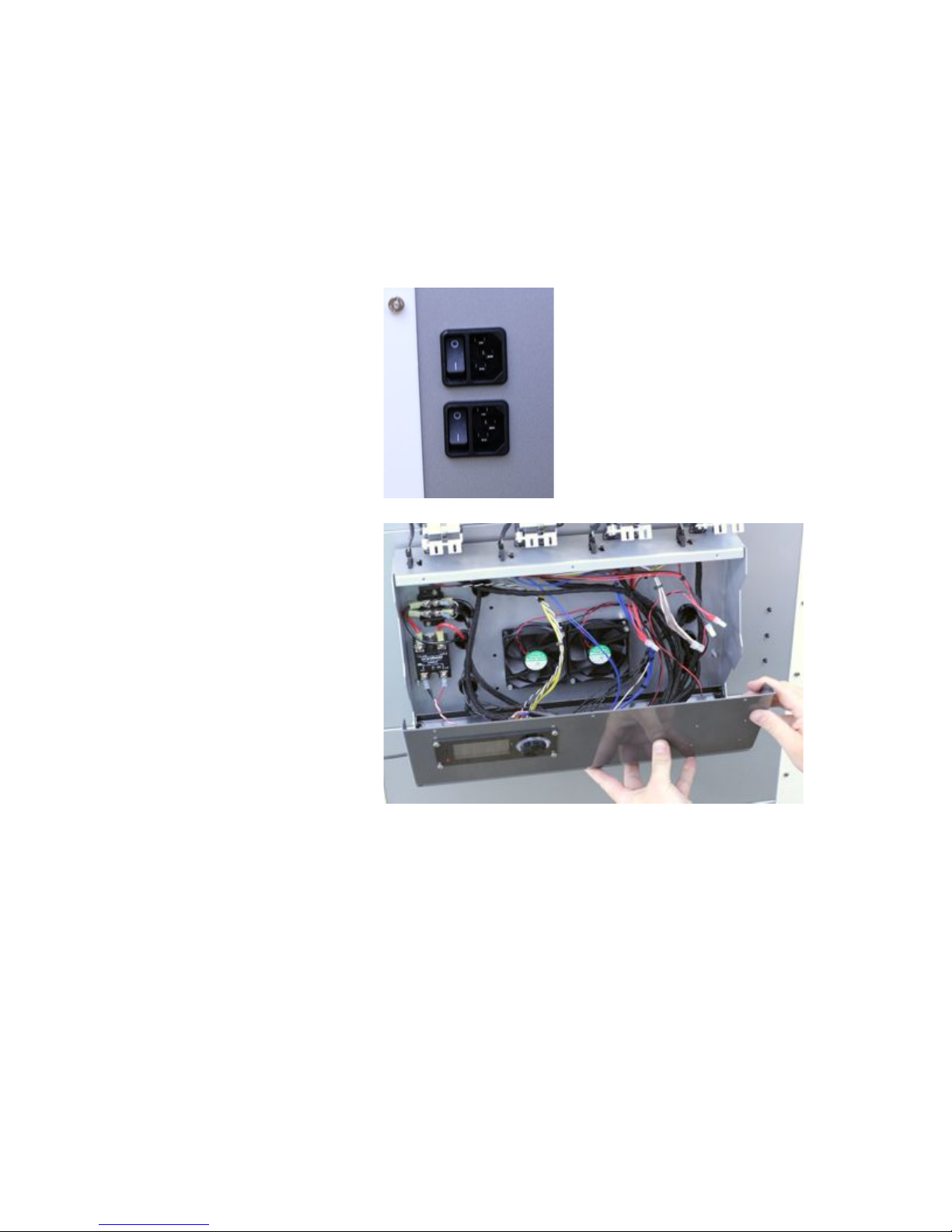
STACKER S4 USER GUIDE 75
Step 1. Disconnect Power
Cords. Make sure the
printheads are cool before you
turn off and unplug the printer.
Step 2. Carefully remove the
three small screws at the top of
the controller housing on the
back of the printer. Once the
screws are removed, the
controller housing will swing
open. Open the controller
housing SLOWLY! If you do
not support the housing with
your hands, it will swing open
and wires can detach from the
electronics. Only open the
housing enough so you can
view the USB input on the far
left corner of the controller card.
11. Useful Information
11.1. Connecting and disconnecting the USB Cable
Your printer ships with the USB cable attached to the printer. In the unlikely situation where the
USB cable becomes detached, or if you would like to remove the USB cable, please follow the
following steps to attach or detach the USB cable from the printer.
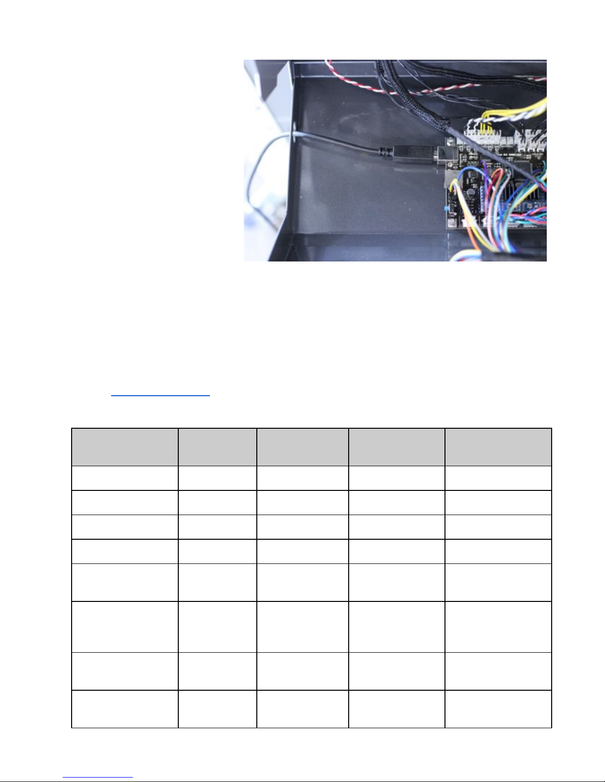
STACKER S4 USER GUIDE 76
Step 3. The USB cable runs
through a hole along the side of
the controller housing. A USB
standard B connector is located
on the lower left side of the
controller card. When
connecting or disconnecting the
USB cable, run the USB cable
through this hole (as shown).
Step 4. Close the controller housing. Secure the controller housing with all three screws.
Filament
Nozzle
Temp. (C)
Bed Temp. (C)
Speed
Fan After First
Layer
PLA/PHA
220°
60°
45mm/sec
Yes
colorFabb_XT
255°
75°
35mm/sec
No
colorFabb_HT
280°
100°
40mm/sec
No
colorFabb nGen
237°
70°
45mm/sec
No
colorFabb nGen
Flex
260°
75°
15mm/sec
No
NinjaFlex
SemiFlex,
MakeShaper TPU
225°
60°
15mm/sec
No
Woodfill‡,
Bamboofill, Corkfill
220°
60°
40mm/sec
Yes
Brassfill, Bronzefill,
Copperfill, Steelfill
225°
60°
30mm/sec
Yes
11.2. Filament Settings Reference
The numbers below are being provided as a starting point when attempting to use various filaments.
Because the size and shape of printed parts varies greatly, some prints may require adjustments to
temperatures and speed. If you are struggling in finding good settings for a part, please contact
Stacker info@stacker3d.com and ask for help. We will gladly help to find working settings for your
printed parts.

STACKER S4 USER GUIDE 77
‡
Due to the fibrous nature of Woodfill filament, it is prone to jamming on smaller nozzles
(e.g., 0.40mm and 0.50mm nozzles). If you are experiencing clogged nozzles with Woodfill,
switch to an 0.60mm or larger nozzle.
11.3. Printer Settings for a Slicing Engine
Because the Stacker S4 is a new printer, most slicing software will not have a default profile
available. To create a profile, you will likely need to enter the follow information:
Printer Name: Stacker S4 - 050 Nozzle
Machine type: Cartesian robot
Firmware: RepRap Repetier
Baud Rate: 250000
Build Volume:
X-Axis: 510mm
Y-Axis 360mm
Z-Axis 600mm
Nozzle Diameter: 0.50mm
Filament diameter: 1.75mm
Number of Extruders: 4
Heated Bed: Yes
Simplify3D Settings: Stacker’s support page (http://stacker3d.com/stacker-3d-printer-support/)
offers factory files for Simplify3D. Please download and Import these FFF files into your copy of
Simplify3D to use with your Stacker printer.

11.4. Power Supply Data Sheet
STACKER S4 USER GUIDE 78

STACKER S4 USER GUIDE 79
12. Terms and Conditions
STACKER, LLC
TERMS AND CONDITIONS OF SALE & LICENSE
As used herein, “Seller” shall mean Stacker, LLC, a Minnesota limited liability company, or any wholly-owned subsidiary of
Stacker, LLC.
These terms and conditions, and any applicable Seller quotation, sales order acknowledgement and Separate Software
License, along with any other documents incorporated by reference in any of the foregoing (hereinafter collectively the
“Agreement”), bind the buyer (“Buyer”) and Seller as to any hardware products sold by Seller to Buyer (“Hardware”), any
services sold by Seller to Buyer (“Services”), and any software (including without limitation, any embedded software)
licensed or sublicensed by Seller to Buyer (“Software”), and constitute the entire agreement between Buyer and Seller
regarding such sale and/or license.
Also as used herein and as applicable: (1) Hardware, Software and Services are collectively, and as applicable, referred
to as “Goods” and (2) the term “Separate Software License” shall mean a set of terms and conditions that govern the
licensing of specific Software and which is communicated to the Buyer by Seller or by a third party software owner.
This Agreement is subject and expressly limited to the terms and conditions contained in this Agreement. Any terms or
conditions stated by the Buyer in any prior, concurrent and/or subsequent request for proposal, offer, purchase order
and/or other documents are deemed by Seller to be a material alteration of this Agreement and are hereby rejected and
inapplicable unless specifically agreed to in writing by an authorized representative of Seller. Buyer shall be deemed to
have accepted the Agreement and all of its terms and conditions, without exception, if any of the following
events occur: (1) Buyer communicates to Seller its acceptance of the applicable Seller’s quotation and/or sales
documents; (2) Buyer issues Seller a purchase order which includes the same Goods and prices as set forth on
the corresponding Seller’s quotation and/or sales documents; and/or (3) Seller delivers any of the Goods covered
by the applicable Seller’s quotation and/or sales documents.
1. PRICES: Except as otherwise set forth in writing by Seller, the price for Goods shall be as set forth in the
applicable Seller’s quotation and/or sales documents, or if the price is not set forth in any such quotation or
documents, in accordance with Seller then-current list price. Prices set forth in a Seller’s quotation shall be valid for
thirty (30) days from the date of such quotation.
2. SHIPPING, RISK AND TITLE: All shipping dates are approximate and are based on Seller’s prompt receipt of all
necessary information from Buyer to properly process the order. Goods are shipped Ex Works Seller’s facility
(pursuant to Incoterms 2010). Subject to Section 8(a) below, title to the Goods and risk of loss thereto shall transfer
to Buyer upon tender of the Goods to a carrier at Seller’s factory. Buyer shall be responsible for all of the following
related to the Goods: freight, duty and tax costs, risk, securing insurance, customs clearance and related costs, and
arranging for a carrier and determining the method of shipment.
3. TAXES AND DUTIES: Prices do not include applicable taxes, duties or fees, including without limitation, any sales,
excise, value added or goods sold taxes, or any customs duties or fees. Except for taxes due on Seller’s net income,
any taxes, duties or fees payable on any transactions hereunder shall be the responsibility of Buyer, and Seller may
invoice Buyer for any such taxes, duties or fees that are or may be payable by Seller.
4. PAYMENT:
(a) Except as otherwise required by Seller in its sole discretion (e.g., payment in advance, payment by letter of
credit), Buyer agrees to pay Seller’s invoice, in U.S. currency, net thirty (30) days from the invoice date.
(b) If any payment owed to Seller hereunder is not paid when due, Seller may charge Buyer a late payment
charge of one and one-half percent (1½%) per month or, if less, the maximum rate allowed by law, on all past

STACKER S4 USER GUIDE 80
outstanding balances. In the event Buyer fails to make any payment when due, Seller shall have the right,
among other remedies, to terminate this Agreement or to suspend further delivery of Goods under this and/or
other agreements with Buyer. Buyer shall be liable to Seller for all expenses attendant to collection of any past
due amounts, including without limitation, reasonable attorneys’ fees.
(c) Seller reserves a purchase money security interest in the Goods sold only to the extent of the invoiced
amount and solely for the purpose of securing Buyer’s payment obligation hereunder. This Agreement is a
security agreement. At Seller’s request, Buyer agrees to promptly execute any instrument or statement, and
otherwise cooperate with Seller, in order to perfect the aforesaid security interest; provided, however, that in the
event Buyer fails to comply with any such request, Buyer authorizes Seller, or a representative on behalf of
Seller, to sign and file the necessary instruments or statements for the Buyer.
5. DOCUMENTATION: Seller shall provide Buyer with that data/documentation that: (1) is specifically identified in the
applicable Seller’s quotation and/or order documents; and (2) is made commercially available and provided by Seller
with the applicable Goods in Seller’s normal course of business.
6. RECEIVING: Except as set forth in the applicable Seller quotation and/or other applicable Seller documentation
provided with the Goods, Buyer shall be responsible for receiving, storing, installing, starting up and maintaining all
Goods.
7. CANCELLATION: Buyer may cancel its order at any time prior to shipment by providing written notice thereof to
Seller and paying Seller liquidated damages in the following amounts: (a) if the order is cancelled within 10 calendar
days of the Buyer’s purchase order date, then an amount equal to twenty-five percent (25%) of the total order price;
(b) if the order is cancelled within 11 to 30 calendar days of the Buyer’s purchase order date, then an amount equal
to fifty percent (50%) of the total order price; and (c) if the Buyer’s order is cancelled between 31 and 60 days of the
Buyer’s purchase order date, then an amount equal to seventy-five percent (75%) of the total order price. The
parties agree that actual damages stemming from any order cancellation will be difficult to calculate and as such the
parties agree that the aforesaid amounts do not represent a cancellation penalty, but rather a reasonable and good
faith estimate of the actual damages incurred as a result of the cancellation. To the extent Buyer has made any
payments prior to cancellation, Seller may apply any payments against any liquidated damages or other amounts due
Seller under this Agreement.
8. RETURNS:
(a) Allowable Period: For all electronic items, the Seller will accept returns only within ten (10) calendar days
from the date of the Buyer’s receipt of merchandise, subject to a 10% restocking fee. For non-electronic items,
excluding filament, the Seller accepts returns only on unopened items within thirty (30) calendar days from the
date of Buyer’s receipt of merchandise. Filament may not be returned.
(b) Return Process: The Buyer shall arrange and pay all shipping, freight, and customs, taxes, and duties
related to returning merchandise to the Seller. For credit, all merchandise must be returned in its original
packaging. The customer must contact the Seller to be issued a return authorization account (RMA) number. Any
returns made by a Buyer without a return authorization account number will be considered an “Unauthorized
Return” and will not be subject to a refund or credit by the Seller. If the returned product is not received by the
Seller in “Resalable Condition”, the Buyer may not receive credit. “Resalable condition” means the Product has
no sign of: use, wear and tear, cosmetic damage, or any other damage; furthermore, the Buyer is responsible for
any damage to the returned product incurred during the shipping.
9. SOFTWARE:
(a) Seller and/or any applicable third party owner shall retain exclusive right, title and ownership in and to their
respective Software, and the license provided herein does not convey to Buyer any interest in the Software or
any part thereof. Buyer acknowledges and agrees that the Software consists of proprietary material and
information of Seller and/or any applicable third party owner, and is protected under U.S. and foreign copyright
and other intellectual property laws, as well as international treaty provisions.
(b) If a Separate Software License is provided with the Software, referenced on Seller order documents and/or
otherwise communicated to Buyer, then such Software shall be governed, in order of precedence, by the terms
of the Separate Software License and then by any non-conflicting terms hereof. If no Separate Software License
applies, then Seller hereby grants to Buyer, and Buyer accepts, a limited, personal, non-exclusive license,
without the right to sublicense, to use the Software only: (1) with the specific Seller’s manufactured Hardware
that such Software is intended to operate with; or (2) if the Software is not intended to operate with Seller’s
manufactured Hardware, on a single computer owned, leased or otherwise controlled by the Buyer. Any

STACKER S4 USER GUIDE 81
concurrent use of the Software and any use on any local area network or other type of network are not
authorized. Notwithstanding any term in this Section 8(b) to the contrary, Buyer’s license rights in the Software
shall include the right to use the Software in any manner expressly described in any Seller supplied
documentation as described in Section 5 above.
(c) Except as required to be permitted by applicable law, Buyer may not copy, reverse engineer, decompile,
disassemble or modify the Software in any way. The aforesaid Software license does not entitle Buyer to any
Software source code.
(d) Repair of Software may be in the form of available corrections, fixes and/or patches to address Software
bugs or inconsistencies, and/or to address non-conformance with the applicable Software specifications
(collectively “Updates”). Following expiration of the Software warranty, Updates available from Seller shall be
provided to Buyer either: (1) in accordance with Seller’s quoted price therefore; or (2) at no charge if Seller
provides such specific Updates at no-charge on a commercial basis to all of its customers. Seller shall not be
required to make available any new versions and/or releases of any Software that provide new and/or enhanced
features, performance and/or capabilities for the Software (“Upgrades”). In the event Seller does, in its sole
discretion, make any Upgrades available, such Upgrades shall be subject to Seller's quoted price therefore. As
used in this Agreement, Software shall include any Updates and Upgrades made thereto.
(e) Notwithstanding any term or provision in this Agreement to the contrary, and with respect to any Software
and/or any part thereof for which the intellectual property rights are not owned by Seller, including any third party
commercial software and any software commonly referred to as open source code or open source software
(collectively “Third Party Software”): (1) any such Third Party Software shall be governed exclusively by the Third
Party Software owner’s applicable license terms if such terms are provided with or as part of the Third Party
Software; (2) nothing in this Agreement, a Separate Software License or any other agreement shall restrict or
otherwise affect any rights and/or obligations Buyer may have, or conditions to which Buyer may be subject to,
under any open source licenses to any open source code or software provided in or with the Software; and (3)
Seller provides no warranty of any kind, express or implied, with respect to any such Third Party Software, which
is provided “AS IS”; provided, however that Buyer may avail itself to any warranty provided by the supplier of any
such Third Party Software.
(f) The aforesaid Software license(s) shall be nontransferable except as follows: (1) any embedded Software
that is included in and intended to operate with any Hardware shall be transferable with the transfer of the
Hardware to another party provided that such transfer is on terms that do not materially conflict with the Software
license terms in this Agreement; and (2) for Software that is not embedded Software, Buyer shall have a
permanent right to transfer all its Software rights under this Agreement to another party, provided Buyer passes
all the copies of the Software licensed to the other party along with the accompanying documentation and a copy
of this Agreement, and provided that the other party accepts the terms of this Agreement. If you transfer the
Software as permitted herein, you may not retain any copies of the Software for your own use and your license
rights under this Agreement are terminated.
(g) The aforesaid Software license(s) shall continue until and automatically terminate upon Buyer’s breach of
any of the terms hereof.
10. LIMITED WARRANTY: With respect to all Goods, the following warranty terms (“General Warranty Terms”) shall
apply solely during the applicable warranty period set forth in Sections 9(a) through 9(f) below. If Buyer has used the
Goods under normal use and care and discovers any defects in material or workmanship, or any material deviation
from the Goods’ applicable published specifications, and notifies Seller in writing thereof during the applicable
warranty period, Seller shall, at its option, use reasonably commercial efforts to repair or replace that portion of the
Goods found by Seller to be defective in material or workmanship, or in material deviation from the applicable
specifications, or refund the purchase price of such Goods. Any Goods to be returned to Seller for repair or
replacement under this warranty must be returned to Seller’s designated facility and in accordance with Seller’s
then-current return material authorization (RMA) procedures and Buyer must contact Seller and obtain a RMA
number and such procedures prior to any such return. This limited warranty shall not apply in the event any such
defects and/or deviations are based in whole or part by improper or inadequate maintenance, unsuitable power
sources or environmental conditions, improper maintenance, alteration or modification by any party other than Seller
or its authorized representative, storage or handling, accident, repair by a party other than Seller or its authorized
representative, or any other cause not the fault of Seller. Except as expressly set forth in this limited warranty, all
costs incurred by Buyer relating to or arising out of this warranty, including without limitation, those related to

STACKER S4 USER GUIDE 82
dismantling and reinstallation of the Goods, shall be borne by Buyer. Except as expressly agreed to in writing by
Seller prior to shipment, Seller makes no warranty or representation that the Goods supplied hereunder comply with
any local laws, rules, regulations or ordinances, and Buyer shall be responsible for obtaining all permits, licenses,
authorizations and/or certificates required by any regulatory body for installation or use of the Goods. This limited
warranty is the only warranty made by Seller, and SELLER DOES NOT WARRANT THAT THE USE OF THE
GOODS OR ANY PARTS THEREOF WILL BE UNINTERRUPTED OR ERROR FREE, AND THERE ARE NO
OTHER WARRANTIES OR REPRESENTATIONS OF ANY KIND WITH RESPECT TO THE GOODS OR ANY
PARTS THEREOF, EXPRESS OR IMPLIED, INCLUDING WITHOUT LIMITATION, THOSE OF
MERCHANTABILITY, FITNESS FOR A PARTICULAR PURPOSE OR NON-INFRINGEMENT.
(a) Hardware (including embedded Software therein) is warranted for a period of twenty-four (24) months from the date of
shipment by Seller.
(b) Notwithstanding the foregoing, the following parts (“Wear Parts”) are warranted for a period of forty five (45) days: 1)
filament drive gears, 2) belts, 3) bearings, 4) pulleys, and 5) hot ends. Hot ends include the following components: (i)
heater cartridges, (ii) heater blocks, and (iii) thermistors. Adhesive print bed coatings or sheets and glass print beds carry
no warranty.
(c) Services are warranted for a period of ninety (90) days from the date the Services are provided by Seller.
(d) Notwithstanding any of the foregoing, Goods repaired or replaced during the warranty period, or Goods identified as
rebuilt regardless of when purchased, are warranted for the longer of the remainder of the original warranty period or
ninety (90) days from the date of shipment by Seller.
(e) Software is warranted for a period of ninety (90) days from the date of “shipment”. As used herein, “shipment” shall mean
either: (1) the date the Software is physically shipped by Seller to Buyer (with or without Hardware); or (2) the date the
Software is electronically transmitted to Buyer by Seller.
(f) No warranty is extended with respect to third party owned software. Notwithstanding any language in this limited
warranty to the contrary, Seller shall have the right to discontinue the availability of any Goods or components or
replacement parts therefore, or to make design changes or improvements in the Goods at any time and such
discontinuance or change shall not constitute a breach of warranty, or result in any liability or obligation to Seller
whatsoever, including, without limitation, any obligation to retrofit, change or improve Goods purchased by Buyer prior to
the discontinuance or change.
11. LIMITATION OF REMEDY AND LIABILITY: THE SOLE AND EXCLUSIVE REMEDY FOR BREACH OF
WARRANTY HEREUNDER SHALL BE LIMITED TO REPAIR, REPLACEMENT OR REFUND UNDER THE LIMITED
WARRANTY SET FORTH IN SECTION 9 ABOVE. IN NO EVENT, REGARDLESS OF THE FORM OF THE CLAIM
OR CAUSE OF ACTION (WHETHER BASED IN CONTRACT, INFRINGEMENT, NEGLIGENCE, STRICT
LIABILITY, OTHER TORT OR OTHERWISE), SHALL SELLER’S LIABILITY TO BUYER AND/OR BUYER’S
CUSTOMERS EXCEED THE PRICE TO BUYER OF THE SPECIFIC GOODS PROVIDED BY SELLER GIVING
RISE TO THE CLAIM OR CAUSE OF ACTION. BUYER AGREES THAT IN NO EVENT, SHALL SELLER’S
LIABILITY TO BUYER AND/OR BUYER’S CUSTOMERS EXTEND TO INCLUDE INCIDENTAL, CONSEQUENTIAL
OR PUNITIVE DAMAGES. THE TERM “CONSEQUENTIAL DAMAGES” SHALL INCLUDE, WITHOUT LIMITATION,
LOSS OF ANTICIPATED REVENUE OR PROFITS, LOSS OF USE OR DATA, DAMAGES BASED ON ANY DELAY
IN PERFORMANCE, AND CLAIMS OF BUYER’S CUSTOMERS. SELLER AND BUYER AGREE THAT THE
LIMITATIONS SET FORTH IN THIS PROVISION SHALL BE ENFORCED TO THE MAXIMUM EXTENT
PERMITTED BY APPLICABLE LAW. TO THE EXTENT PERMITTED BY APPLICABLE LAW, THE LIMITATIONS
SET FORTH HEREIN SHALL EXTEND TO THE BENEFIT OF SELLER’S SUPPLIERS.
12. CONFIDENTIAL INFORMATION. Any information disclosed by Seller to Buyer related to this Agreement, including
quotations, pricing, technical information or otherwise, shall be deemed “Confidential Information”. Buyer shall not
disclose any Confidential Information to any third parties without Seller’s prior written consent and shall use such
Confidential Information only for the purposes reasonably related to the purchase and use of Seller’s Goods. Seller
shall, at all times, retain all right, title and interest in the Confidential Information and all copies thereof.
Notwithstanding the foregoing, Confidential Information shall not include information which is or becomes publicly
known through no wrongful act of Buyer.
13. GOVERNING LAW / DISPUTES:
(a) This Agreement shall be construed, performed and enforced under the laws of the State of Minnesota,
U.S.A.

(b) If Buyer’s address is in the United States, the sole and exclusive venue for any claims or actions under or
related to this Agreement shall be in the applicable court(s) in the city of Minneapolis, Minnesota, U.S.A. If
Buyer’s address is not located in the United States, then Seller and Buyer agree that any controversy or claim
arising out of or relating to this Agreement shall be determined by arbitration in accordance the then-current rules
of the American Arbitration Association by one or more arbitrators appointed in accordance with said rules, and
such arbitration shall be conducted in the city of Minneapolis, Minnesota, U.S.A. Notwithstanding the foregoing,
either party may, at anytime, apply to a court having jurisdiction for a preliminary injunction and/or other equitable
relief where such relief is necessary to protect the party’s interests pending completion or anticipated beginning
of any arbitration.
(c) This Agreement shall be interpreted and construed in the English language and any proceedings and/or
arbitration conducted hereunder shall be in English.
(d) Notwithstanding the foregoing, if applicable law requires that any of the terms and conditions set forth in the
Agreement be different than those set forth in the Agreement, including without limitation, the governing law,
arbitration and/or other dispute resolution terms set forth in this Section 14, then the Agreement shall be deemed
modified and amended to the minimal extent necessary to comply with and incorporate such applicable law, and
the rest of the terms and conditions of the Agreement, as so amended, shall continue in full force and effect.
14. GENERAL PROVISIONS:
(a) Except as expressly set forth in this Agreement, Buyer may not assign this Agreement, or any rights or
obligations hereunder, without Seller’s prior written consent.
(b) No action, regardless of form, arising out of or related to this Agreement, may be brought by Buyer more than
two (2) years after the cause of action has accrued.
(c) Seller shall not be liable for delays in performance or for non-performance due to acts of God, war, terrorism,
riot, fire, labor trouble, unavailability of materials or components, accident, compliance with governmental laws,
rules, regulations, orders or requests, or any other circumstances or causes beyond Seller’s reasonable control.
(d) In the event any of the terms of this Agreement are in conflict with any rule of law or statutory provision, or
are otherwise unenforceable under any applicable laws or regulations, such terms shall be enforced to maximum
extent permitted by the applicable laws or regulations, and to the extent unenforceable, such terms shall deemed
stricken from this Agreement, but such invalidity or unenforceability shall not invalidate any of the other terms of
this Agreement.
(e) No failure by Seller to take any action or assert any right hereunder shall be deemed to be a waiver of such
right in the event of the continuation or repetition of the circumstances giving rise to such right.
(f) Any modification of these terms and conditions must be set forth in a written instrument signed or issued by
duly authorized representative of Seller.
(g) This Agreement is the entire agreement between the parties with respect to the subject matter herein and
supersedes all oral and written communications regarding the subject matter hereof. There are no
understandings, agreements or representations, express or implied, not specified in the Agreement.
STACKER S4 USER GUIDE 83
 Loading...