

Page 1

TPMS Lite Installation Guide ST542119-002
TPMS Lite
Installation Guide
Sensor Installation
Antenna Installation
Configuration Software
Display Gauge
CAN Message Formats
Troubleshooting
Page 2

TPMS Lite Installation Guide ST542119-002
2
This page intentionally left blank.
Page 3
TPMS Lite Installation Guide ST542119-002
3
1. TPMS Lite Sensor Installation
_________________________________________________________
Tools Required
The following tools will be required for the fitting process:
Torx (R) T20 Screwdriver /Torque driver (RS 662-608, DemonTweeks BIKTORXKEY)
4Nm Torque screwdriver ¼” Drive (e.g. Teng Tools 1492SD)
11mm x 50mm Socket (e.g. Teng Tools M140611-C)
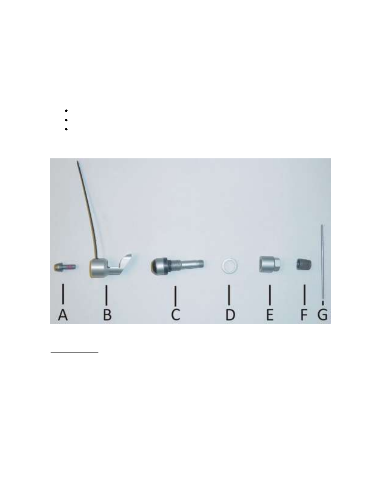
Parts Description
TPMS Fitting Kit
A: Self Locking Torx Screw
B: Sensor
C: Valve
D: Spacer Ring
E: Collar Nut
F: Valve Cap
G: Installation Bar
Page 4
TPMS Lite Installation Guide ST542119-002
4
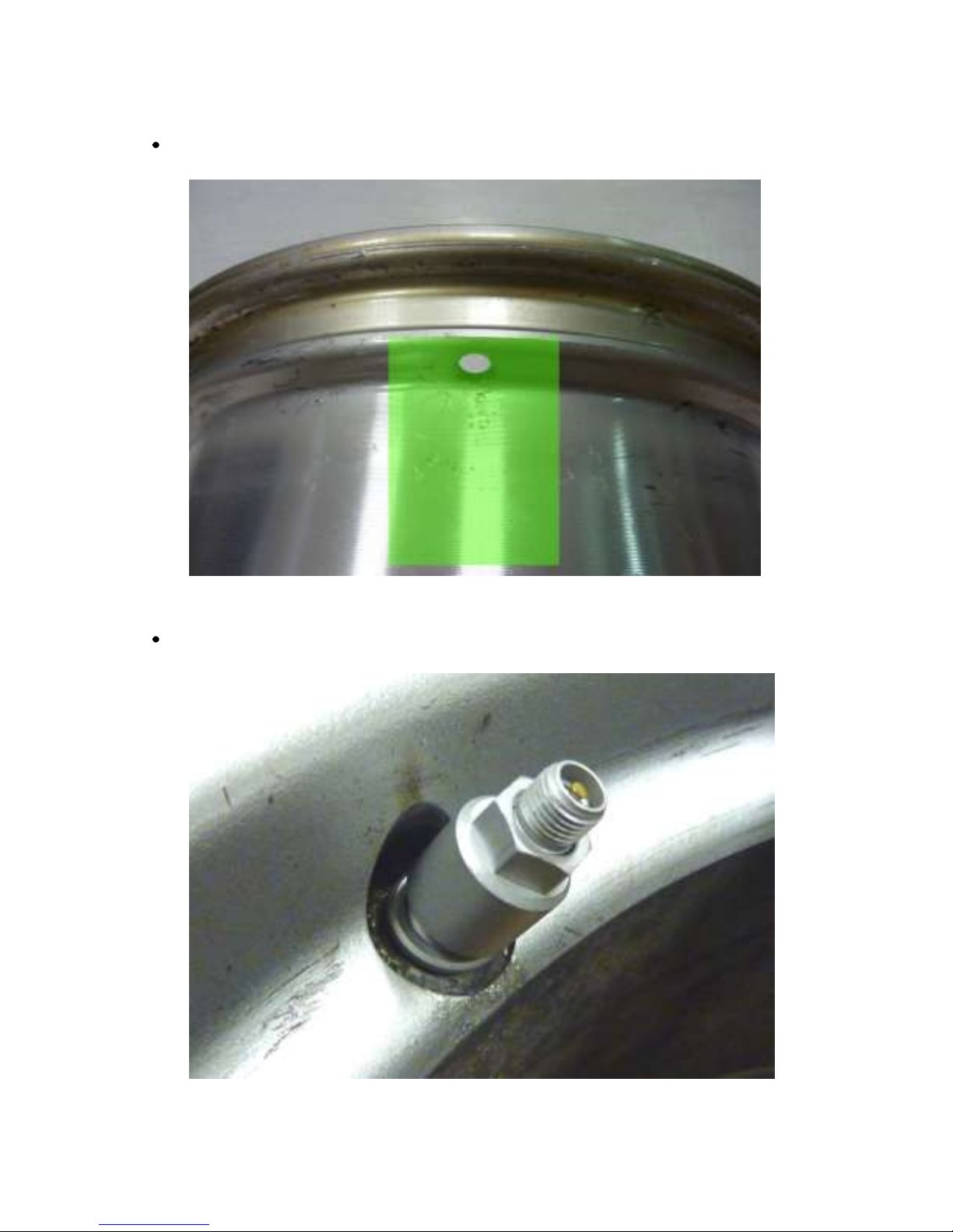
Valve Fitting
Ensure the wheel rim is cleaned and degreased around the valve and wheel well (Green area).
Insert valve into wheel rim. Fit the spacer ring (D) and then the collar nut (E) finger tight.
Page 5
TPMS Lite Installation Guide ST542119-002
5
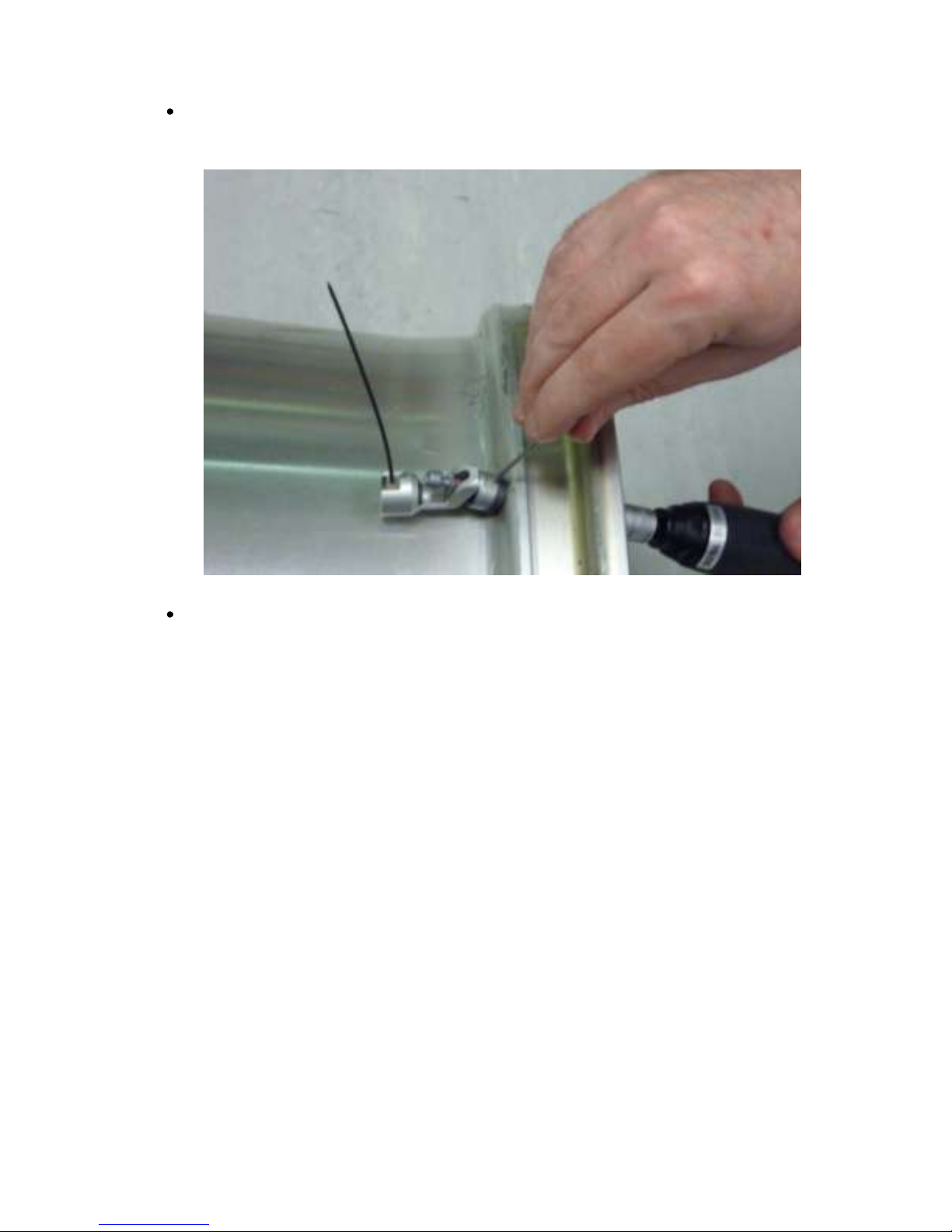
Insert the installation bar (G) into the valve body and tighten the collar nut (E) to a torque of
4Nm +/-0.5Nm
Press the sensor down into the wheel well so that base of the sensor is touching the rim.
NOTE: The base of the sensor must make contact with the wheel rim.
NOTE: The sensor antenna must point away from the centre of the wheel.
Page 6
TPMS Lite Installation Guide ST542119-002
6
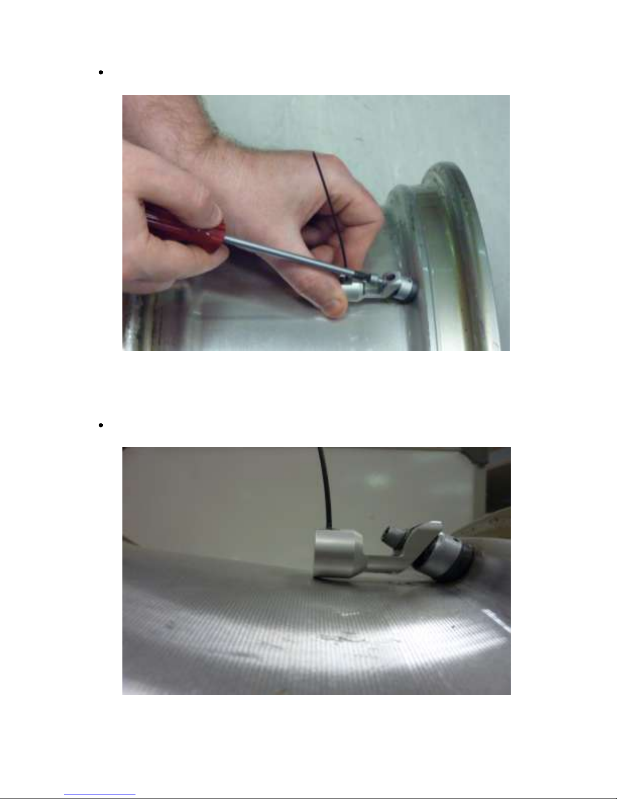
Tighten the Torx screw (A) to 4Nm +/- 0.5N
Once tightened check the sensor is still in contact with the rim.
Page 7

TPMS Lite Installation Guide ST542119-002
7
The sensor is now fitted correctly to the rim and ready for the tyre mounting.
NOTE: It is recommended to fit some identifying mark on the outside of the tyre to indicate
the rim is fitted with a TPMS sensor. This will alert tyre fitters to the fact there is a sensor
fitted and extra care should be taken when mounting/dismounting the tyres.
Page 8
TPMS Lite Installation Guide ST542119-002
8
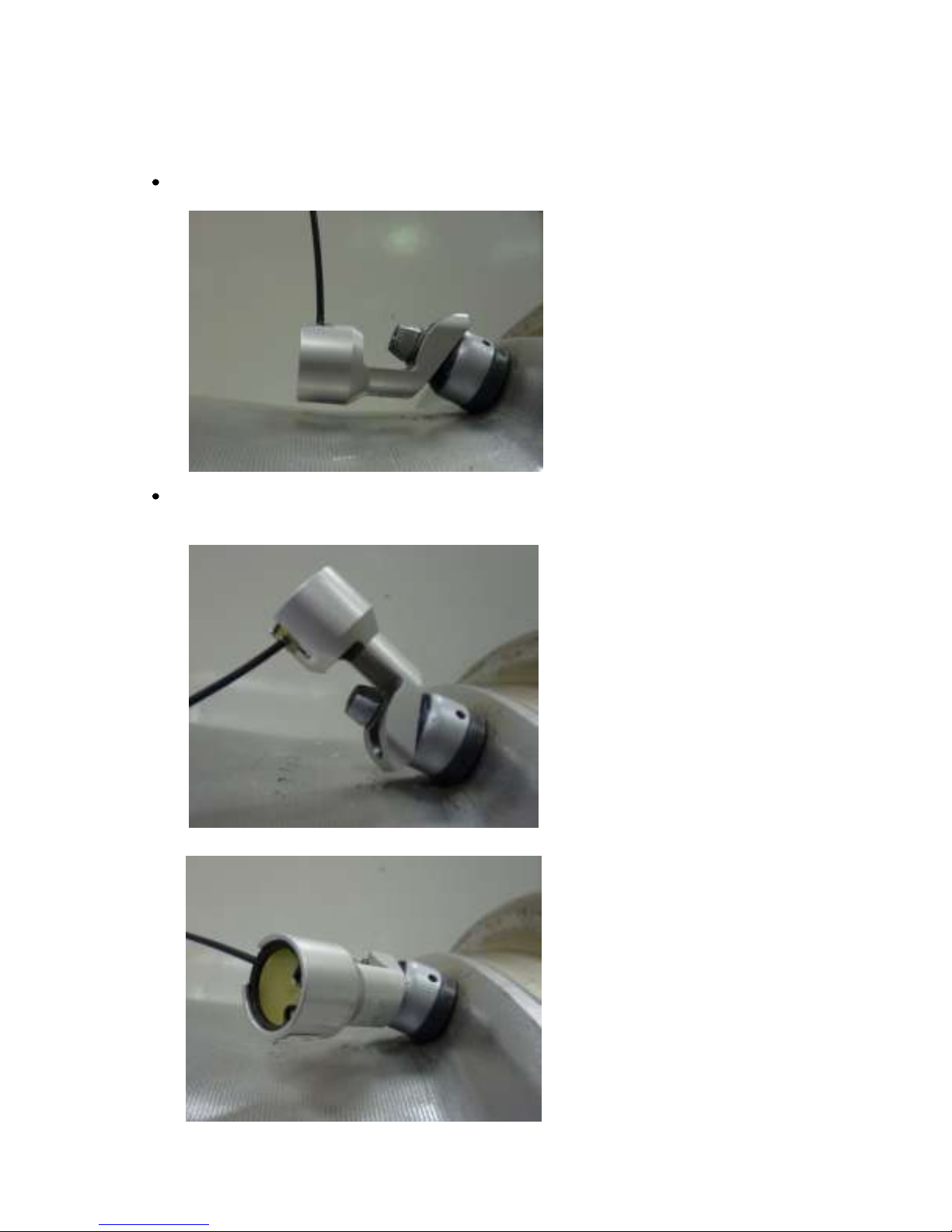
Incorrect Fitting Examples
The following are examples of bad fitment that will degrade the performance of the system:
Sensor not in contact with rim.
X
Sensor antenna pointing away from wheel centre and sensor base not
touching rim.
X
X
Page 9
TPMS Lite Installation Guide ST542119-002
9
2. TPMS Lite Antenna Installation
_________________________________________________________
Introduction
This chapter will describe the fitting of the TPMS Dual-Band Antennas to a vehicle. Please ensure you
read this guide carefully to obtain the best performance out of the system.
Antenna Details
The Stack TPMS antenna is an advanced Dual-Band Antenna (DBA). For optimum system performance,
care should be taken to fit the antennas according to the guidelines in this document. The system
performance can be impaired with poor antenna placement.
The antenna picks up 2 signals. The first is the SAW (433 MHz). This is the signal used to measure
pressure and temperature. The second signal is the RFID or Sensor ID (868 MHz). This is used to pick up
the sensor serial number and the calibration details. Both signals are required for successful operation of
the TPMS system.
Antenna Placement
The goal of choosing an antenna position is to achieve the strongest signal strength for both SAW and
RFID over the widest wheel rotation. There will be some points of wheel rotation where a signal will not
be strong enough to take a measurement. These are generally called NULLS. It is common to have 3 nulls
per rotation of the wheel for the SAW signal.
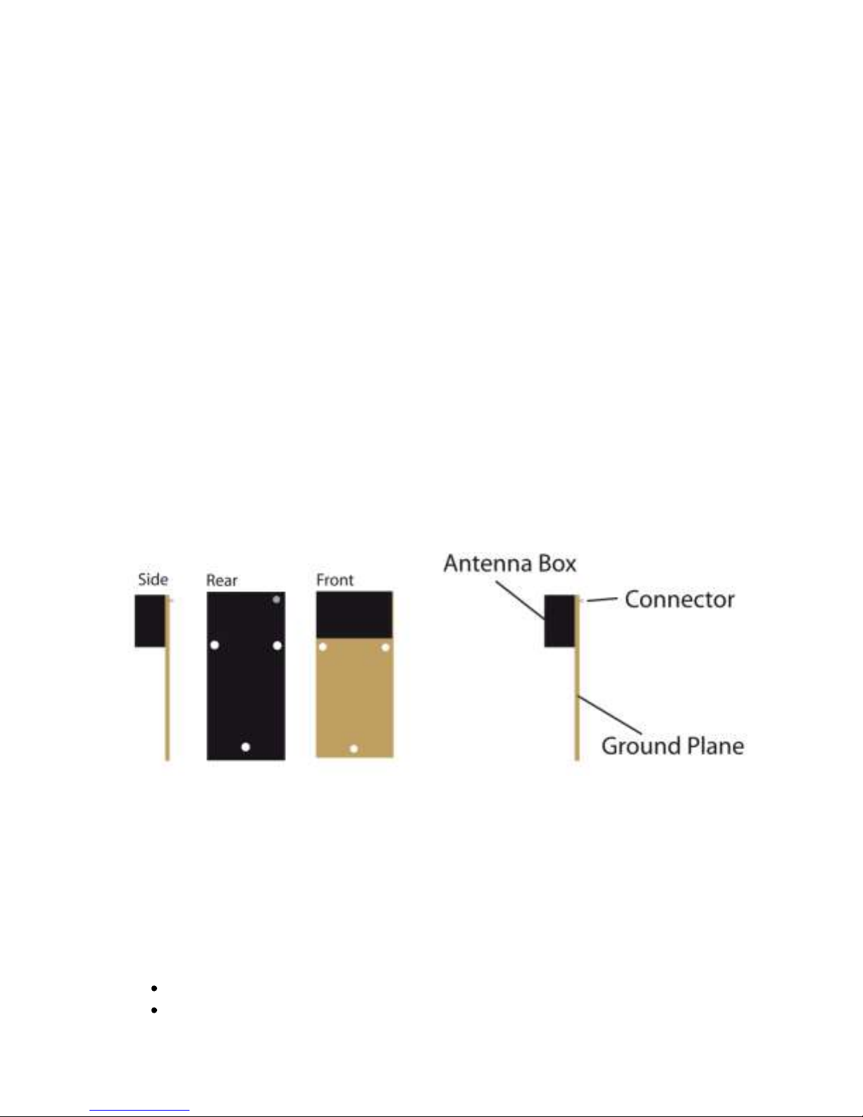
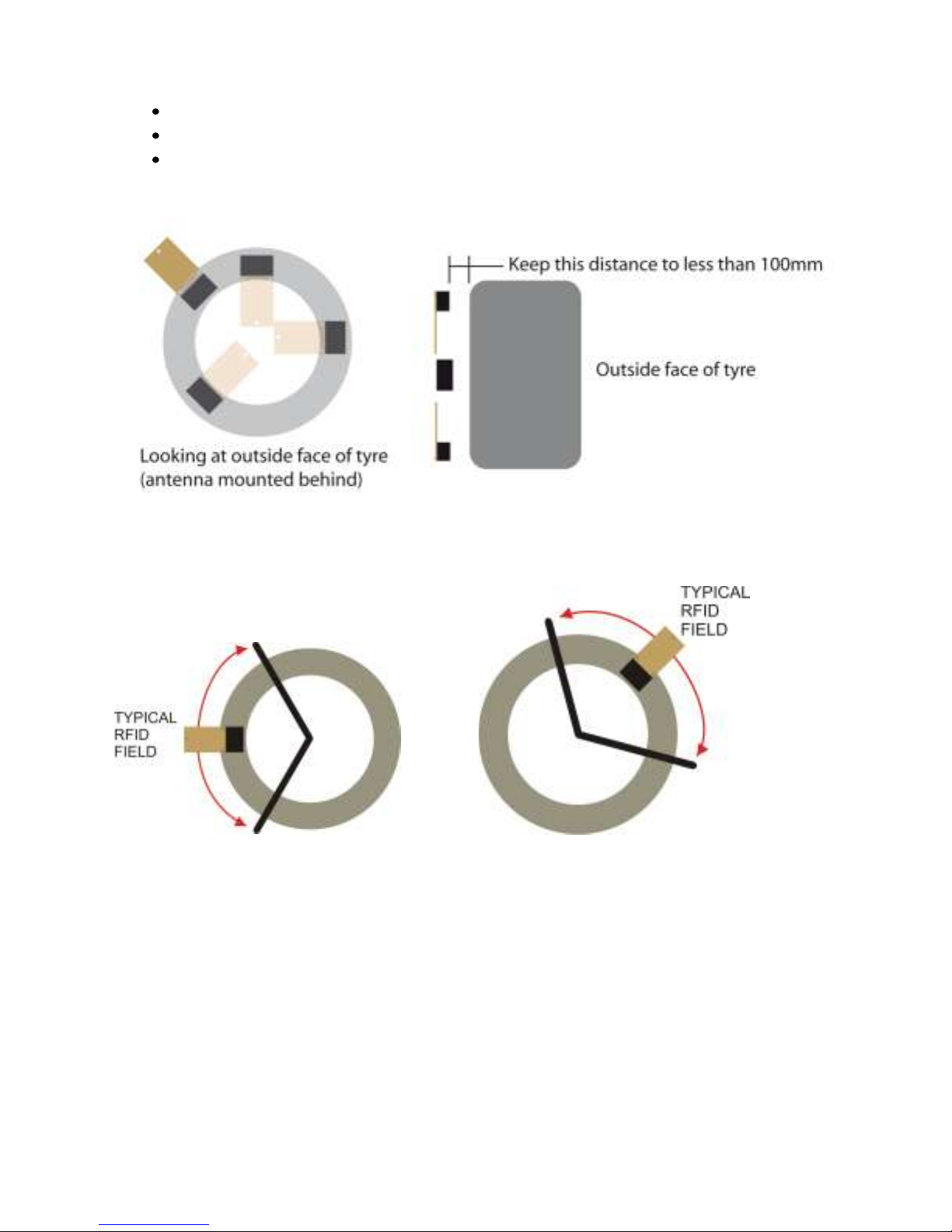
The antenna must be placed as close as possible to the wheel.
The antenna front “box” must be directly in line with the tyre sidewall
Page 10
TPMS Lite Installation Guide ST542119-002
10
The antenna must be mounted radially from the centre of the tyre.
The Ground plane can point towards or away from the centre of the wheel.
The antenna can be mounted behind NON conductive panels (Kevlar, GRP)
In a typical installation you will achieve 90-120deg of RFID coverage and 270 degrees of SAW coverage. It
is important to optimise the RFID coverage to maximise the area at which the RFID can be read over.
Typically the RFID cannot be read outside the area shown above. This should not be a concern when
finding an antenna position as long as you have the coverage shown above.
It is important to get to as close to 120deg of rotational coverage as possible for optimum system
operation.
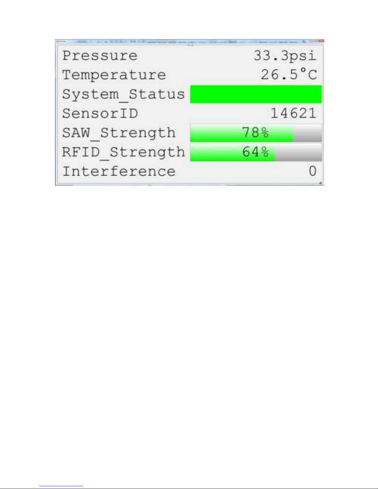
For ease of installation we recommend you use the Monitor mode in the TPMS configuration software.
This can be found on the Monitor tab of the configuration software. Selecting simple monitoring mode
will allow you to see the following information.
Page 11
TPMS Lite Installation Guide ST542119-002
11
The SAW_Strength and RFID_Strength indicators can be used to tune the antenna position.
Antenna Placement
The antenna installation is normally done in several parts. The first is to choose an initial location for the
antenna based on the above guidelines and measure the signal strength during a complete wheel
rotation. This will give a baseline to work from. Then the process is repeated with a new antenna
position. Each time the goal is to increase the wheel rotation coverage or signal strength.
Note: Please ensure that the antenna is secured onto the car with Velcro/dual lock when taking
measurements. Holding the antenna can lead to signal variations.
NOTE: It is strongly recommended that you spend the time at this stage to find the optimum antenna
position as it will significantly reduce the potential for problems later on.
Page 12
TPMS Lite Installation Guide ST542119-002
12
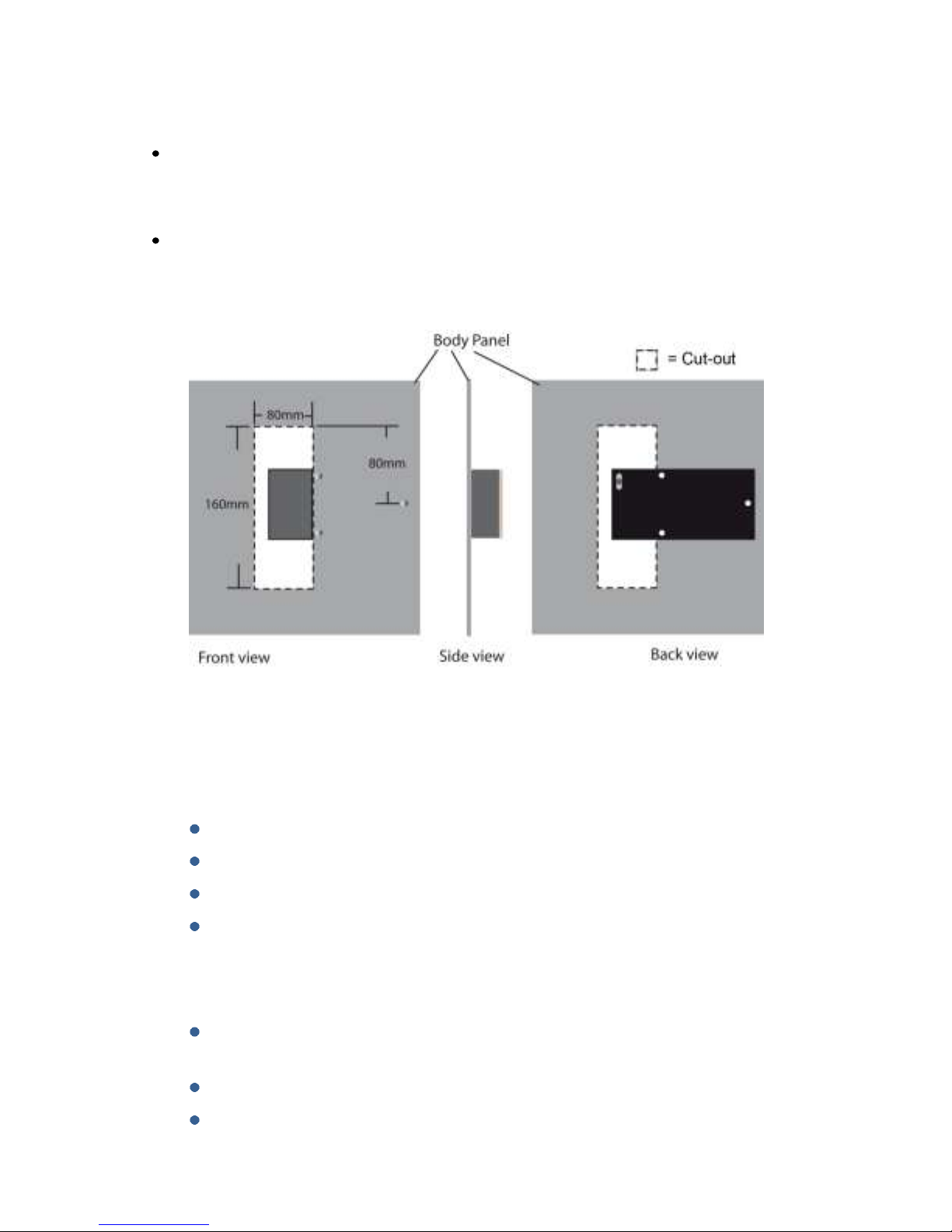
Antenna Placement Restrictions
If you have to mount the antenna to a conductive surface (metal, carbon) then you MUST
space it off the surface by 10mm. Dual lock is ideal for this.
Should you have to mount the antenna behind a conduction surface then please ensure that
you cut a window for the antenna that is the same as the dimensions below. This is essential
for the correct operation of the antenna.
Antenna Do’s and Don’ts
Do
Ensure the antenna is mounted following the guidelines in this manual
Take the time to ensure the antenna placement and tuning is as good as possible
Make sure the RFID signal can be read over at least 90deg of wheel rotation
Ensure the SAW signal is as strong as possible throughout the whole wheel rotation
Don’t
Mount the antenna behind a conductive panel (Carbon, Metal) without first making the
hole as above in the panel
Don’t hold the antenna when performing the installation. Use dual lock
Don’t cut or modify the ground plane of the antenna. This is crucial for correct
operation.
Page 13

TPMS Lite Installation Guide ST542119-002
13
Example Antenna Installation Log
Keeping a hard copy log during antenna installation is a useful way of capturing the data in the field but
can also be helpful in aiding a Stack engineer diagnose possible problems with an installation. A sample
log may look like this:
A blank example log for your use is printed overleaf.
Page 14

TPMS Lite Installation Guide ST542119-002
14
Page 15

TPMS Lite Installation Guide ST542119-002
15
3. TPMS Lite Configuration Software Set-up
_________________________________________________________
Introduction
This guide will describe the TPMS configuration software and how to use the features in it. This software
can be used to configure the TPMS control unit and to monitor the values in real time being measured.
System Requirements
The TPMS configuration software is compatible with the following 32-bit and 64-bit operating systems:
Microsoft® Windows 7
Microsoft® Windows Vista SP2
Microsoft® Windows XP SP3
Connecting to the TPMS Interrogator
1. Double click on the TPMS Configuration Utility icon on the desktop or by
navigating to Start->All Programs->Stack Limited->TPMS Configuration Utility.
2. After a few seconds, the main screen will appear. Please take some time to become familiar
with this screen and the layout. Some of the options will remain greyed out and nonselectable until a connection is made to the TPMS interrogator.
Note: Please ensure that 115200 is selected as the Baud Rate.
Select Serial port
Select Baud Rate
Connect to Box
Disconnect from Box
Connection Status
Page 16

TPMS Lite Installation Guide ST542119-002
16
3. Select the Serial (COM) port you have connected the TPMS Control unit to and press the
Connect button. If the connection is made to the box the program will display to the
Information Tab and display the information for the unit. To confirm a connection has been
made the Connection Status changes from Disconnected to Connected.
Reading and Writing Configurations
The software will automatically read the configuration from the interrogator when the Connect
button is pressed.
Any changes that are then made to the configuration will need to be written to the interrogator.
This is done with the Write Config button. The Write Config button is only activated when the
configurations of the interrogator and config software do not match. The Config Status will show
Up-To Date if they match and Modified if they don’t.
The Read Config button can be used to get the configuration from the interrogator at any time.
Connection Status
Page 17

TPMS Lite Installation Guide ST542119-002
17
CAN Configuration
The TPMS interrogator has a fully configurable CAN bus output. This is used to send data to the
TPMS gauge and can also be used to connect the system to a data logger.
Note: The gauge is fixed to received CAN data on ID 1440 (FL), 1441(FR), 1442(RL) and 1443(RR).
The gauge expects and will only function with these CAN IDs.
To configure the CAN options click on the Wheel CAN ID tab.
CAN IDs
The interrogator outputs a CAN data message per wheel. By default the interrogator
outputs on IDs 1440 to 1443. These are the IDs the TPMS gauge reads. The CAN IDs can
be changed to suit the system the TPMS is connecting to.
Read Config
Read Config
Config Status
CAN IDs
CAN Receive ID
Gauge Fitted
CAN Bit Rate
Page 18

TPMS Lite Installation Guide ST542119-002
18
CAN Receive ID
The TPMS interrogator can receive data over the CAN bus.
Display Fitted
Unchecking this option stops the TPMS interrogator sending the CAN messages to the
gauge. This is useful if the gauge CAN IDs are taken by another device on the system and
should not be sent out by the TPMS interrogator.
Checking this option allows the CAN IDs of the interrogator to be changed while keeping
the gauge functionality.
CAN Bit Rate
The bit rate of the TPMS interrogator can be selected. If the TPMS system is not being
connected to an external data logger then this can be left at 1Mbit. If the system is
being connected to a data logger, set this to the bit rate of the system you are
connecting it too.
Real-time Monitoring
The configuration software can be used to display real time information from the TPMS interrogator.
This is useful during installation and the running of the system.
To enable the real time monitor click the Monitor tab, then click the Monitor button
Note: The monitor window can be resized by dragging the bottom right corner to the size desired.
Front Left
Front Right
Rear Left
Rear Right
Page 19

TPMS Lite Installation Guide ST542119-002
19
The Monitor window displays the values from each of the 4 wheels. The monitored parameters are listed
below.
Parameter
Range
Optimum
Description
Pressure
0-320psi
N/A
Measured pressure
Temperature
0-320DegC
N/A
Measured temperature
System Status
Green
No Sensor Detected
Sensor Detected - Trying to measure
Sensor Detected - Measuring Pressure and Temp
Sensor ID
0-65000
N/A
ID of sensor on that corner
SAW Strength
0-100%
100%
Strength of the pressure and temperature signal
Interference
0-100%
0%
Amount of external radio interference
The monitor window allows for a single corner to be expanded to fill the screen. This also allows that
corner to update faster allowing for more instantaeous feedback. To expand a corner to full screen, click
the icon. To return to the 4 corner view click the icon again.
It is possible to customise the monitor window. Right click on any of the corner displays and a pop-up
menu will appear.
The description of each parameter can be found in the table below.
Parameter
Range
Description
Text Colour
-
Sets the text colour for the corner
Back Colour
-
Sets the background colour for the corner
Temp Units
DegC/DegF
Sets the temperature display units
Press Units
Psi/Bar
Sets the pressure display units
Grid Lines
Yes/No
Shows or hides the grid lines
Text Colour
Back Colour
Temp Units
Press Units
Page 20

TPMS Lite Installation Guide ST542119-002
20
To close the monitor window click the red X in the corner . This will close the monitor window and
return to the main program.
Importing Sensors
The TPMS Lite system allows for 3 sets of wheels to be configured. Each set can contain up to 4
sensors. The sensors need to be imported to the TPMS sensor library before being configured for
use in the box. The action of importing a sensor in also authorises it for use with the system.
Note: To add a sensor to the library the TPMS config software must be used. The library is stored
on the local PC.
Sensor Importing and Authorisation
The pincodes can be found on the outside of the sensor packaging and on the id card supplied with
each sensor. If you have difficulty locating your pin code please contact your dealer.
To import pincodes click the Pincodes tab.
Click the Import button and select the location on the computer where the pincode files
have been saved, then click OK.
NOTE: It is possible to enter the pincode without a file by entering it into the pincode input
and clicking the add button. This authorises and adds the sensor to the library.
Import Pincodes
Manual Pincode
Page 21

TPMS Lite Installation Guide ST542119-002
21
The configuration utility will scan the directory and list the sensors that are available for
importing. You can identify the sensors you have by looking at each sensor’s individual
label which has its id printed on it.
Select the sensor ids that are to be imported. The select all button will select all sensors
in the list. Once they have been selected click the import button. The sensors will now
be imported and authorised for use with the system.
Page 22

TPMS Lite Installation Guide ST542119-002
22
To export the pincode library click the export button, select the directory to export the pincode
files too, select the files required and click Export. The files will be saved in the directory specified
Configuring Wheel Sets
Once the sensors have been added to the library and authorised it is now possible to configure the wheel
sets. Depending on the system purchased sensors can be autorised for use in the following ways:
PRO Systems
To authorise sensors in a Pro system. Click on the Sensor ID tab.
In this mode the sensors that are authorised in the interrogator can be fitted to any corner of the vehicle
and the interrogator will automatically discover the sensor.
Select All
Import
Page 23

TPMS Lite Installation Guide ST542119-002
23
The sensors that have valid imported PIN codes will now be listed.
Unchecked Black text = Pincode Valid not authorised in the interrogator
Checked Black text = Pincode valid and authorised in the interrogator
Checked Red text = Sensor authorised in interrogator but no valid pincode in library
Select each sensor by ticking the checkbox next to the sensor id. When all the sensors required are
selected press the Write Config button to send the sensor list to the
NOTE: Any sensor highlighed red will be unable to be selected or deselected until a valid pincode for that
sensor is imported into the library.
Page 24

TPMS Lite Installation Guide ST542119-002
24
To assign a sensor to a set, click on the corner and a drop down of the sensors that are
authorised will appear.
Select the sensor required for this corner.
Note: The configuration software will only allow valid sensor assignments, for example it
is not possible to select the same sensor in the same wheel set.
To disable a corner, for example on a motorbike or if a sensor has not been fitted select
none. This will stop the interrogator measuring that channel.
When the set configuration is complete, select the wheel set that should be used by default when the
box is powered up.
Set Configuration
Selected Set
Sensor IDs
Page 25

TPMS Lite Installation Guide ST542119-002
25
The wheel set configuration can be written to the box by pressing the write config button.
Misc. Options
The “misc.” options allow the user to configure the way the atmospheric compensation and out of range
values are handled by the interrogator.
The atmospheric compensation value can be handled by setting the atmospheric pressure manually. This
is typically done at the start of each day. It is also possible to send the interrogator the atmospheric
pressure over the CAN link from an existing logger. In this mode the compensation can be more accurate
as it compensates in real time from an existing sensor reading.
The CAN spec is covered in Section 5 of this document.
The out of range values tell the interrogator how to handle a loss of signal from a sensor. Should a sensor
become damaged and the interrogator is unable to read temperature and pressure from it after 10secs
the interrogator will set the output from that channel to either of the two following states:
Hold last Value
this keeps the last value that was successfully measured with the sensor on the output
until the sensor can be read again.
Default Pressure/Temperature
this will force the output to the values defined if the sensor cannot be read. For example
this can be set to a large value outside normal operating range so it is very clear when
the sensor is not being read.
Page 26

TPMS Lite Installation Guide ST542119-002
26
Atmospheric Adjust
Out-Of-Range Adjust
Page 27

TPMS Lite Installation Guide ST542119-002
27
4. TPMS Lite Display Gauge Installation
________________________________________________________
Introduction
The TPMS display gauge has been designed to display pressure and temperature data in real-time from a
Stack TPMS system. The gauge allows you to set alarms and parameters to alert you to tyre problems
while the vehicle is running on track.
Connection & Setup
The gauge is connected to the TPMS interrogator via the NET harness connection. The gauge is powered
via this connection too. The gauge is operated using the two switches on the gauge and two external
switches. These switches can be located near to the driver to enable easy and quick operation of the
gauge.
NOTE: The TPMS Interrogator still requires power supplied even when connected to a Stack Data
Logging product.
Page 28

TPMS Lite Installation Guide ST542119-002
28
Gauge Layout
The gauge has been designed to provide a clear and simple view of the status of the tyres on the vehicle.
There is also a numeric display which can display any of the pressures or temperatures required for more
in depth information.
Pressure and Temp status LEDS
The pressure and temperature status LED’s at the top of the gauge illuminate when each corner is
selected to indicate which parameter is displayed on the numeric display. There is a red and green LED
for each one. The green LED indicates that the parameter being displayed is “normal” and within limits.
The red LED indicates the parameter being displayed is outside the thresholds set.
Numeric display
Pressure Status
Temperature Status
Corner Indicators
Switches
Page 29

TPMS Lite Installation Guide ST542119-002
29
Corner Indicators
In normal operation the gauge will display the status of the tyres via 4 LEDS on each “corner” of the
gauge. These corners are positioned on the dial to reflect the real life position of the wheels on the
vehicle this allows for quick “at a glance” feedback.
The coloured LED descriptions are as follows:
LED
Description
Red
Alarm state present on Corner
Green
Wheel OK
Blue
Low Temperature*
Amber
No sensor detected in wheel
Red LED
- will illuminate if the gauge detects an alarm state on that corner. If the red LED is illuminated you
should be aware that one of the parameters is now outside the thresholds set.
Green LED
- indicates that the wheel is working within the thresholds set.
Blue LED
- illuminated when the temperature is lower than the low temperature threshold.
*The blue LED will illuminate when the LOT menu (see Configuration Menus on Page 3 for details) is set
to “ind” and the measured temperature is below the low temperature threshold.
Amber LED
- will illuminate when the system does not detect a sensor in the wheel. If a sensor is fitted then please
refer to the troubleshooting guide.
Page 30

TPMS Lite Installation Guide ST542119-002
30
Alarms
The gauge features a configurable pressure and temperature thresholds for each of the wheels. There is
an upper and lower pressure limit and an upper and lower temperature threshold. The wheels are
constantly monitored to see if they fall outside these thresholds. If they do the gauge will display an
alarm.
Acknowledging Alarms
To acknowledge an alarm press switch 1, this will clear the alarm display. The RED corner LED will remain
illuminated until the actual alarm condition is cleared.
Configuration Menus
To enter the menus press the switch on the gauge.
To scroll through the menu items press the switch on the gauge.
When you have reached the menu item you wish to edit press the switch on the gauge.
The menus are shown below:
Menu
Description
Value Scroll Mode
Display Mode
Pressure Units
Temperature Units
Threshold Type
Pressure Threshold High
Pressure Threshold Low
Temperature Threshold High
Temperature Threshold Low
Low Temperature Alert Type
Switch 2 Function
Low Brightness Level
Corner Display Timeout
Note: If no user input is detected within 5 seconds after entering the menu the gauge will return to realtime mode.
Page 31

TPMS Lite Installation Guide ST542119-002
31
Menu Descriptions
– Scroll Mode
This sets the way the gauge scrolls round the temperature and pressure values that are displayed on the
numeric display. The options are as follows:
Scroll Order
Mode 1 2 3 4 5 6 7 8
FL Pres
FR Pres
RL Pres
RR Pres
Back to 1
NA
NA
NA
FL Temp
FR Temp
RL Temp
RR Temp
Back to 1
NA
NA
NA
FL Pres
FR Pres
RL Pres
RR Pres
FL Temp
FR Temp
RL Temp
RR Temp
Back
to 1
FL Pres
FL Temp
FR Pres
FR Temp
RL Pres
RL Temp
RR Pres
RR Temp
Back
to 1
To change the menu option, press the switch on the gauge to cycle through them. To select the new
option press the switch on the gauge.
The gauge will now flash the chosen value 5 times then display S-C (Save – Cancel) to save the selection
press the switch and to cancel the change press the switch.
The gauge will now return to real time mode.
– Display Mode
This menu controls how the gauge should display the values selected above. There are 3 options for this:
: The gauge will automatically scroll round each reading in the order set in the SCr menu.
Each value will be displayed for 3seconds before moving onto the next.
: The gauge will scroll round each reading in the order set in the SCr when SW1 is pressed.
Each press of SW1 will move the display on 1 parameter.
: The gauge will display no value until SW1 is pressed. Each press of SW1 will move the
parameter on to the next one. If no user input is detected within the time set in the TIO menu
then it will return to a blank display.
To change the menu option, press the switch on the gauge to cycle through them. To select the new
option press the switch on the gauge.
The gauge will now flash the chosen value 5 times then display S-C (Save – Cancel) to save the selection
press the switch and to cancel the change press the switch. The gauge will now return to real
time mode.
Page 32

TPMS Lite Installation Guide ST542119-002
32
- Gauge Threshold Type
The gauge thresholds can be setup to work in two different ways.
- (Single) in this mode all wheels are compared against a single pressure band and a
single temperature band.
– (Separate) each wheel has its own pressure and temperature threshold band.
To change the menu option, press the switch on the gauge to cycle through them. To select the new
option press the switch on the gauge.
The gauge will now flash the chosen value 5 times then display S-C (Save – Cancel) to save the selection
press the switch and to cancel the change press the switch.
The gauge will now return to real time mode.
- Gauge Thresholds
The options within this menu change depending on the setting:
In = (Single) mode the threshold is set and applies to all wheels.
To change the threshold press – to decrement the value and to increment the value.
When you have reached the desired value wait for 3seconds, the new value with flash 5 times
and then display S-C (Save- Cancel)
Press – to save and to cancel the changes.
The gauge will now return to real time mode.
In = (Separate) mode
the wheel must be selected first before the threshold is set. The threshold only applies to that
wheel.
To change the selected Wheel press - to edit the threshold value press . The current
threshold value will be displayed.
To decrement the value press – and to increment the value press . When you have
reached the desired value wait for 3 seconds and the value will flash 5 times then the display
will show S-C (Save – Cancel).
To save the change press – to cancel press .
The gauge will now move onto the next wheel. To skip this wheel press -.
Page 33

TPMS Lite Installation Guide ST542119-002
33
- Pressure Units
The pressure units can be selected as either PSI or Bar.
To change the menu option, press the switch on the gauge to cycle through them. To select the new
option press the switch on the gauge. The gauge will now flash the chosen value 5 times then display
S-C (Save – Cancel) to save the selection press the switch and to cancel the change press the
switch.
The gauge will now return to real time mode.
– Temperature Units
The temperature units can be selected as either DegC (C) or Deg (F)
To change the menu option, press the switch on the gauge to cycle through them. To select the new
option press the switch on the gauge.
The gauge will now flash the chosen value 5 times then display S-C (Save – Cancel) to save the selection
press the switch and to cancel the change press the switch.
The gauge will now return to real time mode.
– Low Temperature Alert Type
The type of alert when there is a low temperature on a wheel can be selected. The two options are “ind”
indicator or “alm” alarm.
This is useful if you want to know your tyres are below temperature but the conditions are such that this
does not necessarily indicate an alarm. A typical example is on a warm up lap out of the pits.
To change the menu option, press the switch on the gauge to cycle through them. To select the new
option press the switch on the gauge.
The gauge will now flash the chosen value 5 times then display S-C (Save – Cancel) to save the selection
press the switch and to cancel the change press the switch.
The gauge will now return to real time mode.
Page 34

TPMS Lite Installation Guide ST542119-002
34
– Switch 2 Function
Switch 2 can be configured for 3 functions.
– Illumination Level
Pressing switch 2 will cycle through the 4 brightness levels for the gauge.
– Illumination Toggle
Switch 2 can now be a toggle switch or vehicle input and will toggle between High brightness and
Low brightness. See LBL menu for setting the low brightness level.
– Wheel Set Selection
Switch 2 now selects which tyre set the interrogator used to scale the data.
To change the menu option, press the switch on the gauge to cycle through them. To select the new
option press the switch on the gauge.
The gauge will now flash the chosen value 5 times then display S-C (Save – Cancel) to save the selection
press the switch and to cancel the change press the switch.
The gauge will now return to real time mode.
– Low Brightness Level
This sets the low brightness level for the gauge illumination. There are 4 adjustments steps 0 (Lowest) to
3 (highest). When the S2F menu is set to the illumination is toggled between the highest brightness
level and the low brightness Level.
In the other modes this menu can be used at adjust the brightness of the gauge.
To change the menu option, press the switch on the gauge to cycle through them. To select the new
option press the switch on the gauge.
The gauge will now flash the chosen value 5 times then display S-C (Save – Cancel) to save the selection
press the switch and to cancel the change press the switch.
The gauge will now return to real time mode.
– Parameter Display Timeout
This sets the amount of time that a temperature or pressure reading is displayed when is selected in
the menu. For example setting this to 10 will keep the value displayed for 10 seconds after you press
SW1. The value can be set from 0 to 120. 0 means there is no timeout and the value will remain on the
display indefinitely whereas 1-120 will keep the value being displayed for that number of seconds.
Page 35

TPMS Lite Installation Guide ST542119-002
35
To change the menu option, press the switch on the gauge to cycle through them. To select the new
option press the switch on the gauge. The gauge will now flash the chosen value 5 times then display
S-C (Save – Cancel) to save the selection press the switch and to cancel the change press the
switch.
The gauge will now return to real time mode.
Wheel Set Selection
The TPMS lite system has 3 wheel sets which can be configured. The driver will be able to set which set
the interrogator will read and scale the data for. This will be done by setting the menu to and
then pressing external switch 2 momentarily to change the set number.
With each press the gauge will display the set number in the form , and .
When you have chosen the set you want the set number will remain on the display for 3 seconds. After
that the gauge will return to real time mode and the set number will be changed.
Alarms
If any of the parameters go outside the thresholds defined in the menus then the gauge will generate an
alarm warning for the user. The alarm can be cleared by a single press of external switch 1. This action
will acknowledge the alarm indicated, the display will still indicate an error condition on that corner with
the RED corner LED. However the gauge will return to normal operation mode.
If multiple alarms occur on multiple corners then the alarms will cycled through in the order they
appeared. Each alarm will be displayed for 3 seconds before moving onto the next one.
Page 36

TPMS Lite Installation Guide ST542119-002
36
5. TPMS Lite Control Unit CAN Message Format
_________________________________________________________
Background
This section will describe the CAN message format for the TPMS control unit.
CAN Transmit Message Format
The TPMS control unit outputs the following CAN messages:
Byte0 Byte1 Byte
2
Byte
3
Byte
4
Byte
5
Byte
6
Byte
7
Corn
er
CAN
ID*
Rate
(ms)
SensorID
Pressure
(0.001BAR)
Temp (0.01DegC)
System Status
FL
0x5A0
1000
0-65535
e.g 2094 =
2.094bar
e.g 2094 =
20.94DegC
Bit0 = 1 = No
Sensor
FR
0x5A1
1000
0-65535
e.g 2094 =
2.094bar
e.g 2094 =
20.94DegC
Bit0 = 1 = No
Sensor
RL
0x5A2
1000
0-65535
e.g 2094 =
2.094bar
e.g 2094 =
20.94DegC
Bit0 = 1 = No
Sensor
RR
0x5A3
1000
0-65535
e.g 2094 =
2.094bar
e.g 2094 =
20.94DegC
Bit0 = 1 = No
Sensor
*Factory default settings
The rate is dependent on the system type being used. It can be 1000ms, 200ms or 100ms (1Hz, 5Hz or
10hz)
The CAN ID’s can be changed via the PC configuration software, but the message structure remains the
same.
Page 37

TPMS Lite Installation Guide ST542119-002
37
CAN Receive Message Format
The TPMS interrogator can receive CAN messages to control some parameters
Byte
0
Byte 1 Byte 2 Byte
3
Byte4
Byte
5
Byte6
Byte
7
CAN ID
Car Speed
Atmospheric Pressure
(mb)
Spare
Moving
Mode
Spare
Moving
Flag
0x5A4
U16
U16
N/A
U8
N/A
U8
Car Speed:
This is used to detect the car moving state when the Moving mode is set to 2. The units of this are not
important as long as when the car is not moving the value is zero.
Atmospheric Pressure:
This is used to compensate for atmospheric pressure changes. The units are mBar.
Note: To enable this function you must enable Use CAN derived atmos. Pressure in the Misc tab of the
configuration software.
Moving Flag:
This is the CAN bit that signals the moving state of the car when the Moving Mode is set to 1. Setting this
to 1 will indicate the car is moving and setting it to zero will indicate to the interrogator that the car is
stationary.
Moving Mode:
This sets the mode that the interrogator uses to determine when to scan for wheel changes and new
sensors, i.e. when the car is not moving.
Value Moving Mode
0 Internal
1 CAN Moving Flag
2 CAN WSPD
Note: It is recommended to leave the Interrogator in Internal moving mode.
Page 38

TPMS Lite Installation Guide ST542119-002
38
6. TPMS Installation Troubleshooting
_______________________________________________________
Issue
Possible Solution
Action Needed
Sensor readings
incorrect.
SensorID allocated to wrong
corner in interrogator.
Assign sensor to correct corner.
Sensor is damaged.
Send back?
Atmospheric pressure
compensation set to wrong
value
Set correct pressure or set to
1013 for no compensation.
Issue
Possible Solution
Action Needed
Low signal strength.
Antenna mounting position
incorrect.
Refer to manual.
SMA connector not done up
correctly.
Tighten connectors.
Continued overleaf…
Page 39

TPMS Lite Installation Guide ST542119-002
39
Issue
Possible Solution
Action Needed
No sensors can be
detected.
Sensors not authorised for use
in interrogator.
Add sensors.
Sensor damage
Replace sensors.
Antenna position bad.
Refer to manual.
Antenna cables not done up.
Tighten connectors.
Stack® is a registered trademark of Stack Limited.
Information in this publication is subject to change without notice and does not represent a commitment
on the part of Stack Limited. No responsibility is accepted for error or omission.
Copyright © 2011 Stack Limited
 Loading...