

Page 1
Installation Instructions STACK102
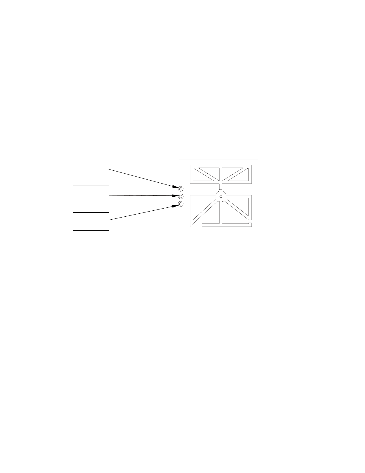
1) Provide 5V DC on pad 1 (4.75V-5.25V)
2) Provide DC groun
d onto PAD3
3) Connect PAD 2 (IF) to the µPC for signal processing
4) Operating temperature: -10-70°C
PAD1
PAD3
PAD2
NOTICE:
This device complies with Part 15 of the FCC Rules and with RSS-210 of Industry
Canada.
Operation is subject to the following two conditions:
(1) this device may not cause harmful interference, and
(2) this device must accept any interference received, including interference
that may cause undesired operation.
NOTICE:
Changes or modifications made to the equipment not expressly approved by Stack
may void the FCC / IC authorization to operate this equipment.
The use of the transceiver is authorized into mobile or fixed devices taking into
account the conditions listed below :
• OEM Integrator may be sure that the end user manual may not contain any
information about the way to install or remove the module from the final
product.
Microwave Sensor
Page 2
• Depends on final host configuration additional authorization requirements for
the non-transmitter functions on the transmitter module may be required (i.e.,
Verification, or Declaration of Conformity) OEM integrator is responsible for
ensuring that after the module is installed and operational into the host, it
continues to be compliant with the Part 15B unintentional radiator
requirements.
• The information on label and user manual is required to be incorporated in the
user manual of the final system. see 47 CFR15 requirements for more details
(e.g. 15.19 / 15.21 / 15.101 / 15.105 / RSS-GEN / ICES)
• Additional label with the words ‘Contains FC
C ID:2AGFX-STACK102’ and ‘Contains
IC:20845-STACK102’ shall be applied and visible from the outside of the end
product.
• The module must be installed and used in strict accordance with the
manufacturer’s instructions as described in the user documentation that
comes with the product.
• The antenna of the module may not be removed, replaced nor modified. The
antenna must not be co-located or operating in conjunction with any other
antenna or transmitter. No additional antenna must be used.
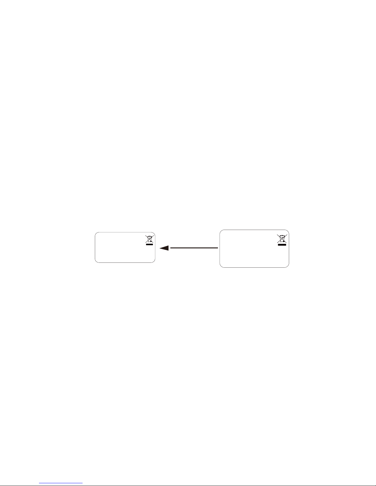
20X12mm
Microwave Sensor
IC:20845-STACK102
FCC ID:2AGFX-STACK102
MODEL:STACK102
Microwave Sensor
IC:20845-STACK102
FCC ID:2AGFX-STACK102
MODEL:STACK102
approved hosts: sensor switch,sensor lighting
Note:These hosts provide power supply regulator to integrate with limited
compliance testing.
 Loading...