

Stack Motorsport DVL User Manual

Part No. ST542113-002
Motorsport DVLs
User Guide


Preface
Stack DVL User Guide i
Preface
Congratulations
Thank you for choosing the Stack DVL. This solid-state
recorder will give you many opportunities to make video
recordings in environments where ordinary video recorders
cannot be used.
Purpose of this User Guide
This user guide will help you install and use the Stack DVL.
It explains how to set up and configure the system for your
application.
Related Products From Stack
If you need information about other Stack products, these
can be obtained from Stack or from your local Stack dealer.
Products available from Stack include :-
Tyre Pressure Monitoring Systems
Digital Video-loggers & Digital Video Recorders
Event Recorders
Multi-function Recorders (MFRs)
Data Analysis Software
Multi-function Displays (MFDs)
Pro-control & Professional Auxiliary Gauges
Intelligent Tachometers & Integrated Displays
Analogue & Digital Sensors
Health & Usage Monitoring Systems (HUMS)
Stack ® is a registered trademark of Stack Limited.
Information in this publication is subject to change without notice and
does not represent a commitment on the part of Stack Limited. No
responsibility is accepted for error or omission.
Copyright © 2011 Stack Limited

Contents
ii Stack DVL User Guide
Contents
Chapter 1. Introduction 1
Chapter 2. Essential User Information 3
Video Standard 4
Using a New Compact Flash Card 4
Playing a Recording 4
Before Making a Recording 4
Deleting Files 5
Chapter 3. Installation 6
CLUBMAN-3 Wiring 8
PRO-4 Wiring 10
Chapter 4. Operation 13
To make a recording: 13
To play a recording: 16
Operation with a new Compact Flash Card 17
Formatting a Compact Flash Card 18
Deleting Files 18
Corrupted Compact Flash Cards 18
Chapter 5. Compact Flash Cards 20
Chapter 6. Configuration 21
PC Connection 21
System Information 23
Video Setup 24
Camera Configuration 27
Audio Setup 30
Advanced AGC 31
Data Recorder 33
Record Control 35
G Sensors 37
Ports 37
Tools 39
Chapter 7. Video and Data Systems 41
Controlling Synchronised Video 41
Manual recording control 42

Contents
Stack DVL User Guide iii
Recording Lamp 43
Recommended Vehicle System Power connections 43
Downloading Video 43
Chapter 8. Troubleshooting 46
Chapter 9. Specifications 47
Appendix A. Mounting Template 49
Appendix B. Wiring Harness Diagrams 51
CLUBMAN-3 Harness (ST918119) 51
PRO-4 System Harness (ST918118) 52
PRO-4 Monitor Harness (ST918114) 52
PRO-4 Input Harness (ST918107) 53
Power Harness (ST918078) 53
Control / Status Harness (ST918105) 54
Appendix C. Upgrading the Firmware 55
Appendix D. Service and Support 58
Stack Web-site 58
Contacting your Dealer 58
Stack Contact Details 61
Index 62

Chapter 1. Introduction
Stack DVL User Guide 1
Chapter 1. Introduction
The DVL is part of Stack's third generation Digital Video
Recorder range. Specially designed for harsh environments,
they provide the optimum solution for capturing audio and
video on the move. Now they record data too...
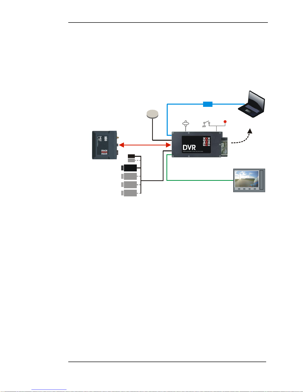
Monitor
CAM 1
CAM 2
CAM 4
CAM 3
ECU
MIC 2
MIC 1
Record
Lamp
Record
Switch
Built-in 3-axis
Accelerometer
USB
Laptop with
Configuration Software
& DataPro
Audio/Video Out
GPS
Receiver
Audio/Video In
Removable
CF
Card to PC
STACK DIGITAL VIDEO RECORDER
STACK
MULTI-FUNCTION
MODULE
Typical DVL Application
Stack's Digital Video Recorders employ broadcast standard
MPEG-2 video compression to record high quality real-time
video and audio direct to a Compact Flash (CF) card. The
card is easily removed and played on a PC or laptop using a
standard media player application. Recordings can also be
copied to DVD for playback on either a PC or DD player.
A data overlay feature is available so that date, time and GPS
data may be stamped onto the recorded video. Connecting
the DVR directly by CAN-bus to a Stack Data System allows
up to 128 channels of data, including GPS and the internal
3-axis G sensor channels, to be recorded alongside the video
and audio. The recording can be viewed and analyzed in the
supplied Stack DataPro analysis software.
Stack DVLs feature a rugged machined aluminum housing
specifically designed and manufactured to protect the unit in
harsh and extreme environments. The unit is compact and

Chapter 1. Introduction
2 Stack DVL User Guide
durable with no moving parts (other than the sealed CF card
access door) and is capable of operating where normal VCRs
or DV recorders can not. Its anti-vibration and shockresistant abilities are perfect for consideration as commercial
off-the-shelf (COTS) equipment. Stack DVLs have been
successfully used in many demanding applications such as
motorsport, military vehicles, aerospace, marine and many
more.
CLUBMAN-3 is perfect for applications that don't require
full environmental protection whilst PRO-4 is a fully
waterproof unit with Motorsport “AS” connectors and a
higher operating temperature range. Both models have an
A/V output for connection to an external monitor.
Recording can be triggered automatically using the built-in
3-axis G sensor, from the Stack MF module or using the
included remote control record trigger switch with status
LED.
Stack DVLs provide superior high-quality video recording in
real time over a wide range of bit rates suitable for different
applications – up to 20 Mbps is available, quality equivalent
or better than DV tape.
Chapter 2. Essential User Information
Stack DVL User Guide 3
Chapter 2. Essential User Information
Please read the important information in this chapter before
using the Stack DVL.
CLUBMAN-3 DVL Standard Components
Quantity
Description
1
ST8310 CLUBMAN-3 Module
1
ST918119 CLUBMAN-3 System Harness
1
ST918105 Switch and Lamp Harness
1
ST169049 USB DVL to PC Lead
1
ST918119 Power lead
1
ST169021 Audio/Video Lead
1
ST920039 DVR Configuration Utility Software
PRO-4 DVL Standard Components
Quantity
Description
1
ST8311 PRO-4 Module
1
ST918118 PRO-4 System Harness (red)
1
ST918107 PRO-4 Input Harness (yellow)
1
ST918114 PRO-4 Audio/Video Harness (blue)
1
ST918119 Power lead
1
ST918105 Switch and Lamp Harness
1
ST920039 DVR Configuration Utility Software
Optional Components
Quantity
Description
1
or
ST918129 Expansion harness for ST8100, ST8130 etc
ST918130 Expansion harness for MF, MFR or MFD etc
up to 4
Bullet Camera (ST8393 PAL or ST8394 NTSC)
up to 4
ST918106 CAM plug to BNC & Power Harness
up to 4
ST169047 2 metre Camera Extension Cable
up to 4
ST39008x Camera Mount
1
Microphone Kit
Compact Flash (CF) Card
1
ST995 GPS Receiver

Chapter 2. Essential User Information
4 Stack DVL User Guide
Video Standard
The DVL can be configured to either the PAL or NTSC
video standard to match the camera which is connected.
!
Only PAL and NTSC are currently supported.
Using a New Compact Flash Card
The DVL will only operate with a Compact Flash card
formatted with a FAT32 File System. Before using a new
card, check its File System by inserting it into a PC running
Windows XP or Vista and display the disk properties by
right clicking the disk icon in “My Computer”. If supplied
as FAT16, reformat to FAT32 (see page 17).
Playing a Recording
The files produced by the DVL are fully MPEG-2 compliant.
They may be played directly from the card by inserting it
into a PC with a suitable Compact Flash card slot or adapter.
However, better replay results are usually obtained by
transferring the file to the PC‟s hard drive (see page 16).
Before Making a Recording
Before a recording session clear the Compact Flash card so
that maximum space is available. Deleting files can cause
the write/read speed of the removable Compact Flash card to
degrade but a format will restore its performance. A format
can be achieved using a PC running Windows XP or Vista.
Right-click on the disk icon in “My Computer” and select
“Format”. Ensure the “File system” is set to “FAT32”,
choose the “Quick Format” option and then click “Start” (see
page 17).
Alternatively click on the “Information” tab in the DVR
Configuration Utility and select “Format”. (see page 23)

Chapter 2. Essential User Information
Stack DVL User Guide 5
Deleting Files
Whilst it is possible to delete files from the CF card, that
won‟t necessarily restore full performance due to file
fragmentation. To restore performance once a recording has
been made, transfer the files to your PC‟s hard drive and then
perform a format.
!
Ensure any useful recordings have been archived before
performing a format.
Chapter 3. Installation
6 Stack DVL User Guide
Chapter 3. Installation
Before installing the DVL, take a few moments to plan the
installation. First identify all the components which came
with your system. You may like to perform a dry run by
connecting the components together to get a feel for how the
final installation will be accomplished.
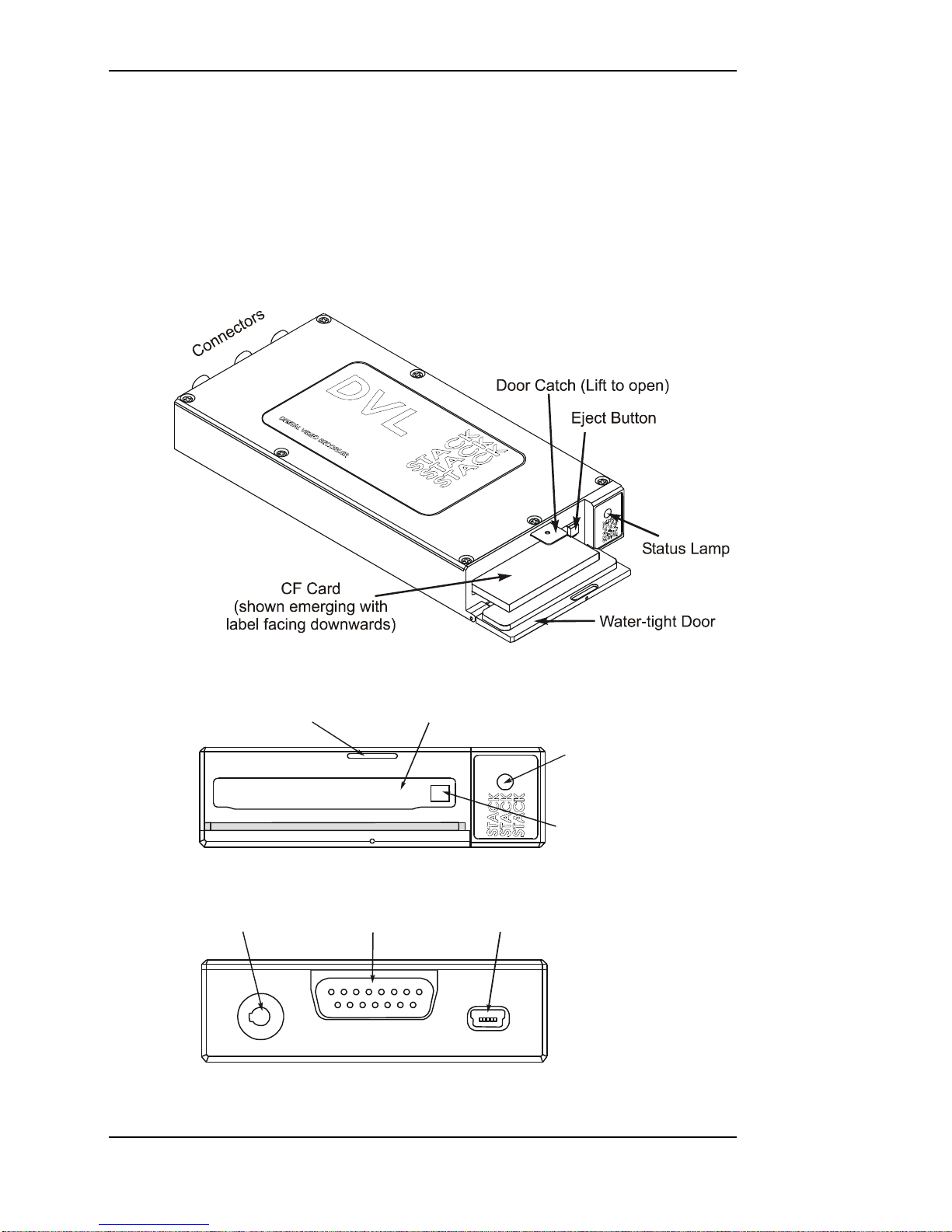
The DVL Module
Status
Lamp
Flash Card Slot
Card Eject Button
Door Catch
The Front Panel showing the Card Slot
USB-B
15-way D Conn
AV Jack
CLUBMAN-3 Rear Panel showing the Connectors

Chapter 3. Installation
Stack DVL User Guide 7
Monitor
(blue)
System
(red)
Input
(yellow)
PRO-4 Rear Panel
Now identify a suitable location for the DVL. It can be
mounted in any orientation but, when looking for a location,
please bear in mind that there must be approximately 50mm
(2”) clearance for the wiring harnesses at the back of the unit
to ensure that the cables will not be bent too sharply. There
must also be enough space to remove the Compact Flash card
at the front.
The module can be mounted by various means including
using double-sided tape or Dual-Lock™. A rigid mounting
can be made to a suitable bracket using the six M3 tapped
holes in its underside (see Appendix A. Mounting Template
for dimensions).
Once a mounting position has been determined, the
components should be connected using the wiring harnesses
supplied. The figures below show the standard electrical
connections to the unit.
If you are using the DVL with a Stack Video Overlay
system, an adapter harness is available for that system. The
differences are described at the end of this chapter. Please
contact your Stack distributor if you need to purchase the
adapter wiring harness.
!
The wiring harnesses supplied by Stack are terminated with
commonly used connectors. If your equipment uses different
connectors, please obtain appropriate adapters, available
from your Stack dealer.
Chapter 3. Installation
8 Stack DVL User Guide
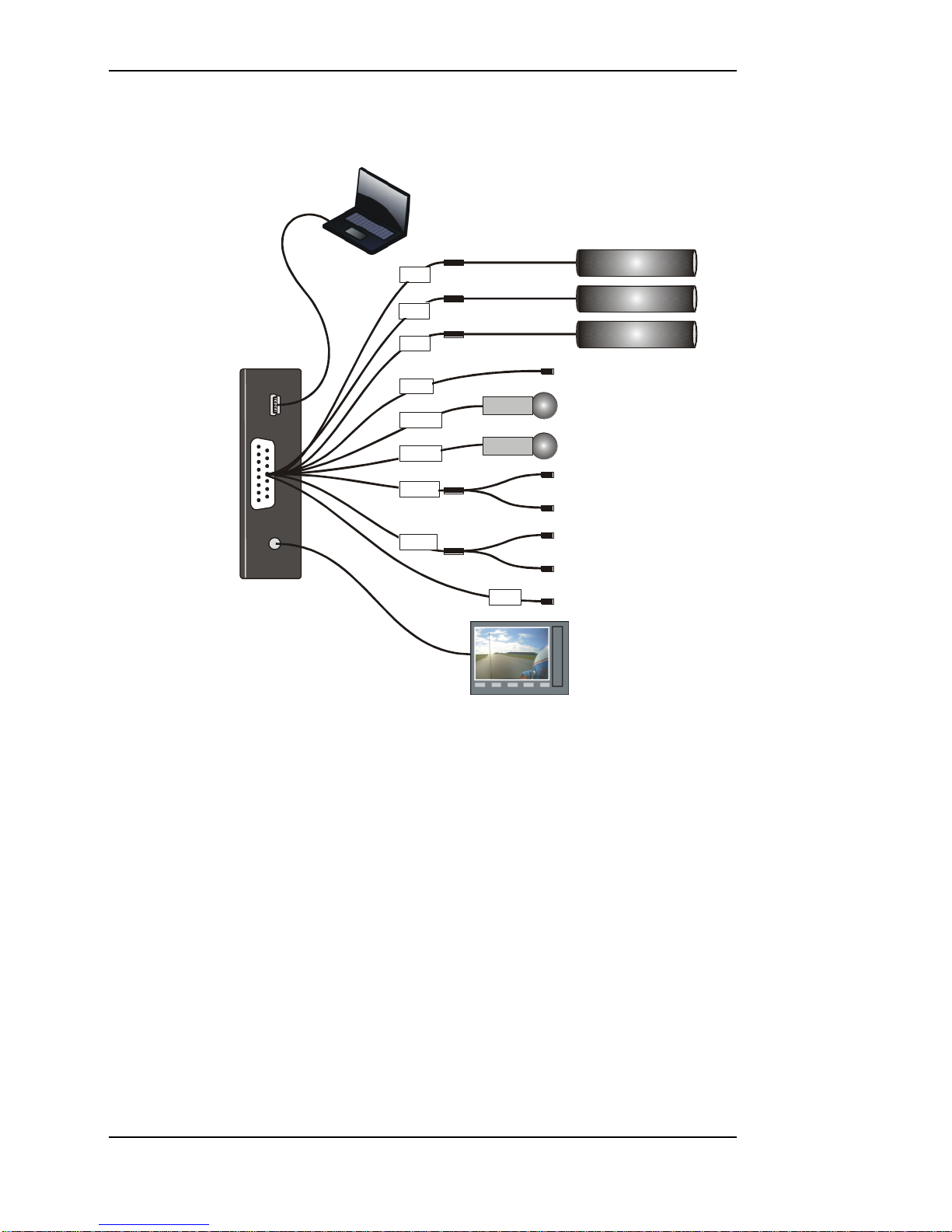
CLUBMAN-3 Wiring
Micro
USB
15-way
D Conn
4-way
Jack
Bullet Cameras
Microphones
Record Switch
Recording Lamp
CAN bus
PC USB Port
Monitor
Power supply
for mics etc
red
NET
12V
C1
CTL
left
right
white
DL
Data Link In (GPS)
C3
C2
Power (9 to 20 volts)
Starting from C1, connect a camera to each of the 4-way
CAM plugs on the wiring harness.
!
If you are using your own cameras, you may need to obtain
the optional CAM plug to BNC and Power leads (ST918106)
from your Stack distributor.
Connect the Record Switch and Recording Lamp lead to the
CTL connector. Extender cables are available from Stack‟s
dealers.
The Recording Lamp output can be used to drive an input on
some other equipment to indicate the DVL is recording.
This is an open collector output and must not be used to
drive more than 25mA max.
Connect a permanent DC supply of between 9 and 20 volts
(or 20 to 50volts for the High Voltage Option ST9399) to the

Chapter 3. Installation
Stack DVL User Guide 9
Power (B+ and B-) connectors. You must provide a 5 amp
fuse in the B+ connection to protect the DVL. An
independent switch can be added to isolate the module.
!
A permanent power supply is required to ensure that
recording finishes cleanly when the Record Switch is turned
off. If the supply is obtained from a vehicle‟s ignition switch,
the DVL could switch off before the recording has finished
and the last few seconds may be lost (see page 18).
The following connections are optional:
If audio recording is required, connect your microphones to
the white (left) and red (right) microphone inputs.
Microphone gain can be adjusted using the DVR
Configuration Utility (see page 30).
A Regulated 12 volt 2.1 mm power connector has been
provided for powering microphones.
!
The regulated 12 volt power also supplies the camera. The
maximum total load is 1.0 Amps so, if the current required is
greater, you must provide a separate power supply.
!
If audio recording is not required, it may be disabled to
extend the recording time (see page 30).
Connect a GPS receiver into the DL (Data Link) connector
input for GPS video overlay (see page 38)
A composite video output is provided via the 4-way AV jack
socket. This can be used to connect to an external monitor to
help align the camera, etc. The video monitor output is the
same as the input. Connect the yellow phono plug to the
video input on your monitor.
Stereo audio monitor outputs are also provided to aid the setup of the microphone levels (see page 30). Connect the
white and red phono plugs to the audio inputs on your
monitor or speakers.

Chapter 3. Installation
10 Stack DVL User Guide
PRO-4 Wiring
Monitor
System
Input
Bullet Cameras
Microphones
Record Switch
Recording Lamp
CAN bus
PC USB Port
Monitor &
Speaker
Power supply
for mics etc
left
right
V
A
Data Link In (GPS)
CTL
DL
red
white
12V
C2
C3
C4
C1
NET
Power (9 to 20 volts)
Plug each harness into the appropriately coloured connector
on the rear panel of the DVL.
Input Harness (yellow)
Starting from C1, connect a camera to each of the 4-way
CAM plugs on the wiring harness.
!
If you are using your own cameras, you may need to obtain
the optional CAM plug to BNC and Power leads (ST918106)
from your Stack dealer.
The following connections are optional:
If audio recording is required, connect your microphones to
the white (left) and red (right) microphone inputs.

Chapter 3. Installation
Stack DVL User Guide 11
Microphone gain can be adjusted using the DVR
Configuration Utility (see page 30).
A Regulated 12 volt 2.1 mm power connector has been
provided for powering microphones.
!
The regulated 12 volt power also supplies the cameras;
maximum total load is 1.0 Amps. If the current required is
greater, you must provide a separate power supply.
!
If audio recording is not required, it may be disabled to
extend the recording time (see page 23).
System Harness (red)
Connect the Record Switch and Recording Lamp lead to the
CTL connector. Extender cables are available from Stack‟s
dealers.
The Recording Lamp output can be used to drive an input on
some other equipment to indicate the DVL is recording.
This is an open collector output and must not be used to
drive more than 25mA max.
Connect a permanent DC supply of between 9 and 20 volts
(or 20 to 50volts for the High Voltage Option ST9399) to the
Power (B+ and B-) connectors. You must provide a 5 Amp
fuse in the B+ connection to protect the DVL. An
independent switch can be added to isolate the module.
!
A permanent power supply is required to ensure that
recording finishes cleanly when the Record Switch is turned
off. If the supply is obtained from a vehicle‟s ignition switch,
the DVL could switch off before the recording has finished
and that recording may be lost (see page 18).
Connect a GPS receiver into the DL (Data Link) connector
input for GPS video overlay (see page 38)
Monitor Harness (blue)
The composite video output can be used to connect to an
external monitor to help align the camera, etc. The video
monitor output is the same as the input. Connect the yellow
phono plug to the video input on your monitor.

Chapter 3. Installation
12 Stack DVL User Guide
Stereo audio monitor outputs are also provided to aid the setup of the microphone levels (see page 23). Connect the
white and red phono plugs to the audio inputs on your
monitor or speakers.

Chapter 4. Operation
Stack DVL User Guide 13
Chapter 4. Operation
To make a recording:
Check that video, power and a Record Switch are connected
as described in Chapter 3. Check that the Record Switch is
set to the open (off) position.
!
A red marker on the Record Switch indicates when it is in the
recording position.
If not already installed, open the waterproof door and ensure
the Eject Button is pushed fully home. Insert a Compact
Flash card into the slot until it is flush with the opening.
Once inserted, close the waterproof door.
!
The Compact Flash card must only be inserted with its
manufacturer‟s label facing downwards and the lip
uppermost. If there is resistance, the card is probably upside
down. Attempting to insert the card incorrectly will damage
the DVL and void the warranty.
Apply DC power and after about a 20 second delay (while
the system boots up), the Status Lamp on the front panel will
light showing the status of the unit.
If the Status Lamp shows static green the system is ready to
record.
If the Status Lamp is not static green, refer to the table below
to find out the DVL‟s status.
!
Before making a recording, ensure there is enough space
available or preferably, clear the Compact Flash card (see
page 4). Card space may be checked on a PC or by making
a trial recording and viewing the DVL‟s Status Lamp (as
described below).

Chapter 4. Operation
14 Stack DVL User Guide
To start recording close the Record Switch. Once recording,
the Recording Lamp will illuminate and the Status Lamp will
flash green for 3 seconds with a mark space ratio showing
the capacity remaining:
With an empty Compact Flash card the Status Lamp will
flash for approximately 2.7 seconds on : 0.3 seconds off.
With approximately 50% capacity remaining it will flash
1.5 seconds on : 1.5 seconds off.
With approximately 10% remaining the Status Lamp will
flash for 0.3 seconds on : 2.7 seconds off.
To stop recording, open (switch off) the Record Switch. The
Status Lamp will revert to showing static green and the
Recording Lamp will be extinguished.
!
Do NOT remove the CF card whilst recording is in progress
because the data will be corrupted (see page 18).
The Compact Flash card may now be removed and placed
into a PC with a suitable Compact Flash card slot card slot.
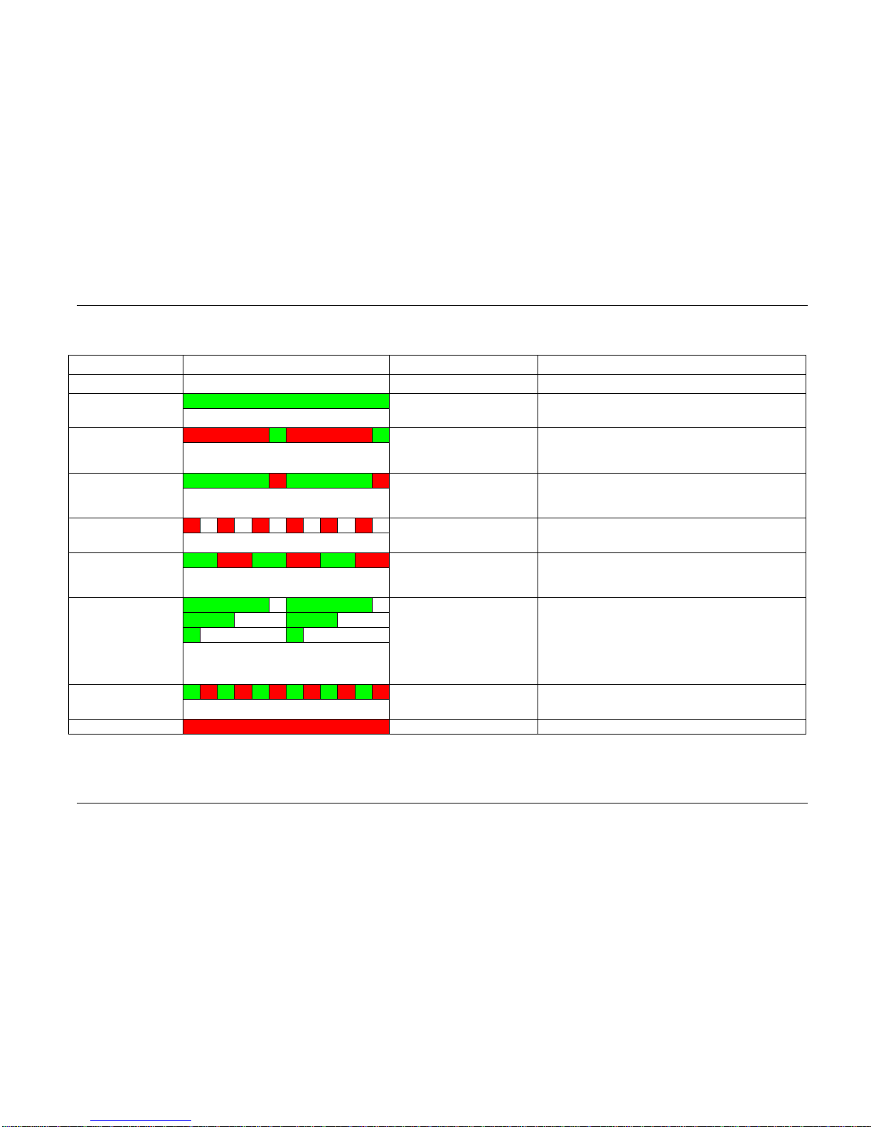
The table below shows the function of the DVL‟s front panel
Status Lamp. Green generally indicates the unit is
functioning correctly and red indicates a fault or reset
condition.
Chapter 4. Operation
Stack DVL User Guide 15
Operation
Status Lamp Operation
Description
Ready
Static green
The DVL is ready to record. Video and card OK.
Video OK, No Card
Flashing long red / short
green
In stand-by or unable to record with card not
present or full. Video input OK. If card present,
reformat with FAT32
No Video, Card OK
Flashing long green / short
red
In stand-by (or unable to record) with video not
present but card OK. Check Camera connection
& power or check PAL / NTSC setting OK
No Video, No Card
Fast flashing red
Unable to record. Video and card not present or
full, or system fault.
PC Connected
Flashing equally
green / red
(0.5s red / 0.5s green)
DVL is under external control of the DVR
Configuration Utility.
Recording 100%
Memory 50%
Remaining 10%
Flashing green
External Recording Lamp
also illuminated
Recording OK. The longer the green flash the
greater the memory remaining. With a new card
the Status Lamp will flash for approx. 2.7 seconds
on : 0.3 off. 50% remaining, lamp flashes 1.5 sec
on : 1.5 off. 10% remaining lamp flashes for
0.3 sec on : 2.7 off.
Recording, No Video
Fast flashing green / red
Recording but video is not present, audio only is
being recorded.
Resetting or Busy
Static red
System reset / preparing to record or card format.
 Loading...