

Page 1
UM2538
User manual
STM32 motor-control pack using the FOC algorithm for three-phase, low-voltage,
and low-current motor evaluation
Introduction
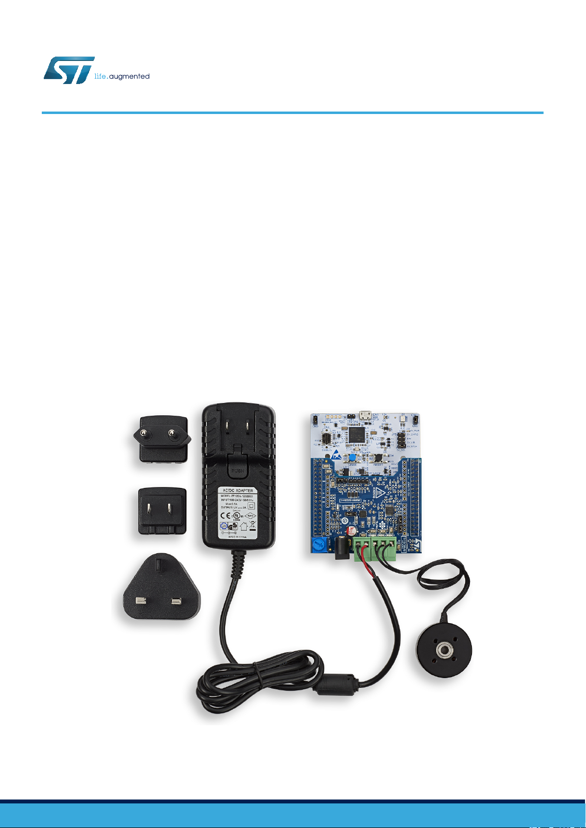
The P-NUCLEO-IHM03 pack is the motor-control kit based on the X-NUCLEO-IHM16M1 and NUCLEO-G431RB boards. The
power board with the STSPIN830 driver in the STPIN family provides a motor-control solution for three-phase, low-voltage,
PMSM motors with the addition of the STM32 Nucleo board through the ST morpho connector as illustrated in Figure 1. P-
NUCLEO-IHM03 is provided with a power supply unit also shown in Figure 1.
The device used on the power board is the STSPIN830. It is a compact and versatile FOC-ready driver for a three-phase motor.
It supports both single- and three-shunt architectures and embeds a PWM current controller based on user-settable values of
reference voltage and OFF time. Thanks to a dedicated MODE input pin, the device offers the freedom to decide whether to
drive it through 6 inputs (one for each power switch) or a more common 3 PWM direct-driving inputs. In addition, it integrates
both the control logic and a fully protected low-RDSon triple-half-bridge power stage. The NUCLEO-G431RB board provides an
affordable and flexible way for users to try out new concepts and build prototypes with the STM32G4 microcontroller. It does not
require any separate probe as it integrates the STLINK-V3E debugger and programmer.
This motor-control evaluation kit is fully configurable to support the closed-loop control (FOC only). It can be used with either a
speed sensor mode (Hall or Encoder), or speed sensorless mode. It is compatible with both 1-shunt and 3-shunt current-sense
topologies.
Figure 1. P-NUCLEO-IHM03 pack
Picture is not contractual.
UM2538 - Rev 1 - April 2019
For further information contact your local STMicroelectronics sales office.
www.st.com
Page 2
1 Features
• X-NUCLEO-IHM16M1
– Three-phase driver board for BLDC/PMSM motors based on STSPIN830
– Nominal operating voltage range from 7 V dc to 45 V dc
– Output current up to 1.5 A rms
– Over-current, short-circuit, and interlocking protections
– Thermal shutdown and under-voltage lockout
– BEMF sensing circuitry
– Support of 3-shunt or 1-shunt motor current sensing
– Hall-effect-based sensors or encoder input connector
– Potentiometer available for speed regulation
– Equipped with ST morpho connectors
• NUCLEO-G431RB
–
STM32G431RB 32-bit microcontroller based on the Arm® Cortex®-M4 core at 170 MHz in LQFP64
package with 128 Kbytes of Flash memory and 32 Kbytes of SRAM
– Two types of extension resources:
◦
◦ ST morpho extension pin headers for full access to all STM32 I/Os
– On-board STLINK-V3E debugger/programmer with USB re-enumeration capability: mass storage,
Virtual COM port, and debug port
– 1 user and 1 reset push-buttons
• Three-phase motor:
– Gimbal motor: GBM2804H-100T
– Maximum DC voltage: 14.8 V
– Maximum rotational speed: 2180 rpm
– Maximum torque: 0.981 N·m
– Maximum DC current: 5 A
– Number of pole pairs: 7
• DC power supply:
– Nominal output voltage: 12 V dc
– Maximum output current: 2 A
– Input voltage range: from 100 V ac to 240 V ac
– Frequency range: from 50 Hz to 60 Hz
UM2538
Features
Arduino™ Uno V3 expansion connector
The STM32 32-bit microcontrollers are based on the Arm® Cortex®-M processor.
Note: Arm is a registered trademark of Arm Limited (or its subsidiaries) in the US and/or elsewhere.
UM2538 - Rev 1
page 2/27
Page 3
2 Ordering information
To order the P-NUCLEO-IHM03, refer to Table 1. Additional information is available from the datasheet and
reference manual of the target STM32.
Order code Boards Target STM32 Additional content
P-NUCLEO-IHM03
2.1 Product marking
Evaluation tools marked as “ES” or “E” are not yet qualified and therefore not ready to be used as reference
design or in production. Any consequences deriving from such usage will not be at ST charge. In no event, ST will
be liable for any customer usage of these engineering sample tools as reference design or in production.
“E” or “ES” marking examples of location:
• On the targeted STM32 that is soldered on the board (for illustration of STM32 marking, refer to the STM32
datasheet “Package information” paragraph at the www.st.com website).
• Next to the evaluation tool ordering part number that is stuck or silk-screen printed on the board.
This board features a specific STM32 device version, which allows the operation of any bundled commercial
stack/library available. This STM32 device shows a "U" marking option at the end of the standard part number
and is not available for sales.
In order to use the same commercial stack in his application, a developer may need to purchase a part number
specific to this stack/library. The price of those part numbers includes the stack/library royalties.
• X-NUCLEO-IHM16M1
• NUCLEO-G431RB
Table 1. List of available products
STM32G431RBT6U
UM2538
Ordering information
• Power supply (12 V dc, 2 A)
• Gimbal motor (GBM2804H-100T)
2.2 Codification
The meaning of the codification of the Nucleo board is explained in Table 2.
NUCLEO-XXYYZT Description Example: NUCLEO-G431RB
XX MCU series in STM32 32-bit Arm Cortex MCUs STM32G4 Series
YY MCU product line in the series STM32G431
Z
T
The order code is mentioned on a sticker placed on the top side of the board.
Table 2. Nucleo-board codification explanation
STM32 package pin count:
• R for 64 pins
STM32 Flash memory size:
• B for 128 Kbytes
64 pins
128 Kbytes
UM2538 - Rev 1
page 3/27
Page 4

3 Development environment
3.1 System requirements
• Windows® OS (7, 8 and 10), Linux® 64-bit, or macOS
• USB Type-A to Micro-B cable
Note:
macOS® is a trademark of Apple Inc. registered in the U.S. and other countries.
UM2538
Development environment
®
3.2
Note:
Development toolchains
• Keil® MDK-ARM (see note)
• IAR™ EWARM (see note)
• GCC-based IDEs
On Windows® only.
3.3 Demonstration software
The demonstration software, included in the X-CUBE-MCSDK STM32Cube Expansion Package, is preloaded in
the STM32 Flash memory for easy demonstration of the device peripherals in standalone mode. The latest
versions of the demonstration source code and associated documentation can be downloaded from www.st.com.
UM2538 - Rev 1
page 4/27
Page 5
4 Getting started (basic user)
4.1 System architecture
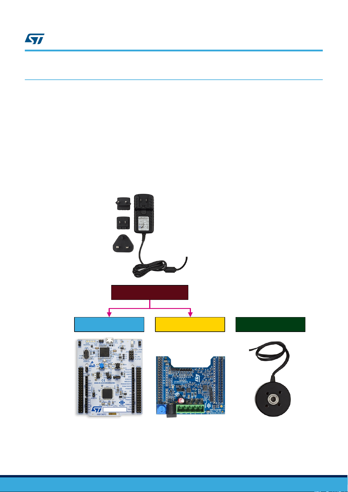
The P-NUCLEO-IHM03 kit is based on the usual four-block architecture for a motor-control system :
• Control block: it interfaces user commands and configuration parameters to drive a motor. The PNUCLEO-IHM03 kit is based on the NUCLEO-G431RB board that provides all needed signals to perform the
proper motor-driving control algorithm (for instance FOC).
• Power block: the X-NUCLEO-IHM16M1 is based on a 3-phase inverter topology. The core of the power
block embedded on board is the STSPIN830 driver, which embeds all the necessary active power and
analog components to perform a low-voltage PMSM motor control.
• PMSM motor: low-voltage, 3-phase, brushless motor.
• DC Power supply unit: it provides the power for the other blocks (12 V, 2 A).
Figure 2. Four-block architecture of the P-NUCLEO-IHM03 pack
UM2538
Getting started (basic user)
Power supply unit
Control Power PMSM
UM2538 - Rev 1
page 5/27
Page 6
UM2538
Configure and run the motor control from the STM32 Nucleo motor-control pack
4.2 Configure and run the motor control from the STM32 Nucleo motor-control
pack
The P-NUCLEO-IHM03 Nucleo pack is a complete hardware development platform for the STM32 Nucleo
ecosystem to evaluate a motor-control solution with a single motor.
For operating the standard pack, follow these hardware configuration steps:
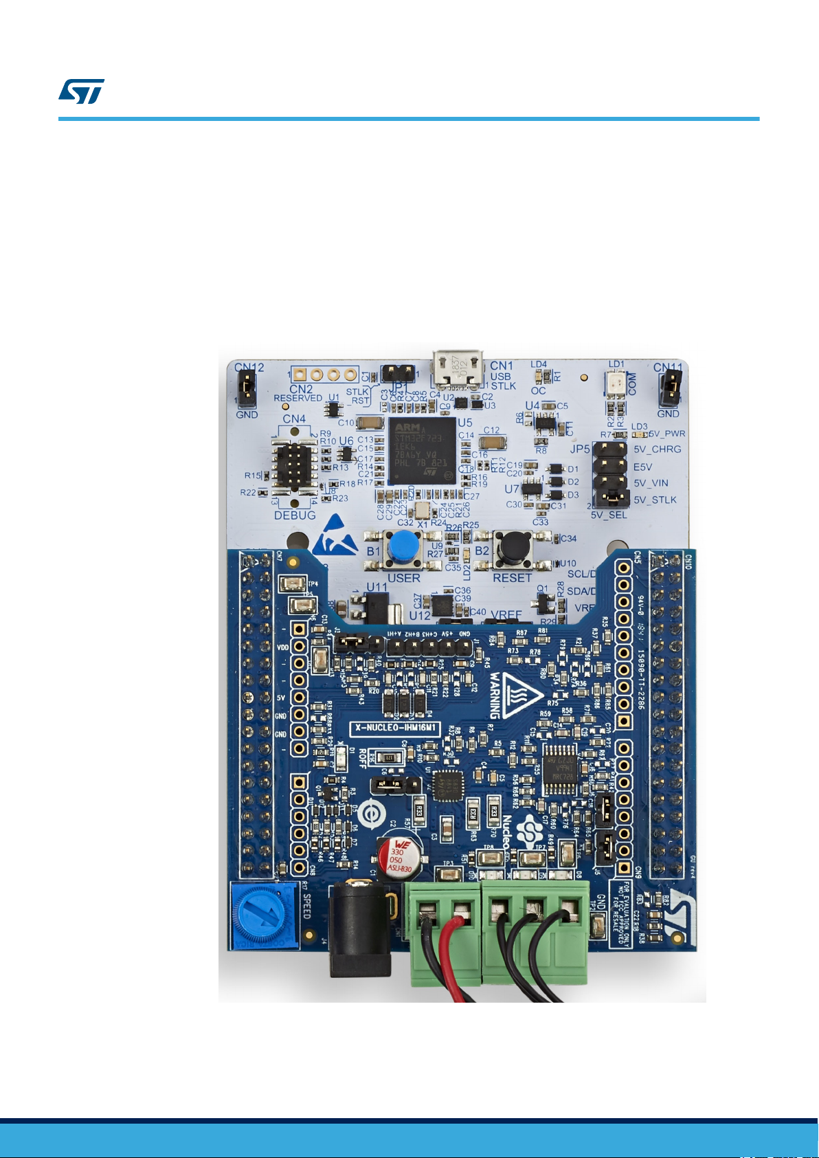
1. The X-NUCLEO-IHM16M1 must be stacked on the NUCLEO-G431RB board through the CN7 and CN10 ST
morpho connectors. There is only one position allowed for this connection, in particular the two buttons on
the NUCLEO-G431RB board (blue button B1 and black button B2) must be kept out, as shown in Figure 3.
Figure 3. X-NUCLEO-IHM16M1 and NUCLEO-G431RB assembled
UM2538 - Rev 1
The interconnection between the X-NUCLEO-IHM16M1 and the NUCLEO-G431RB board is designed for full
compatibility with many control boards. No modification of solder bridges is required for the use of the FOC
algorithm.
page 6/27
Page 7
Configure and run the motor control from the STM32 Nucleo motor-control pack
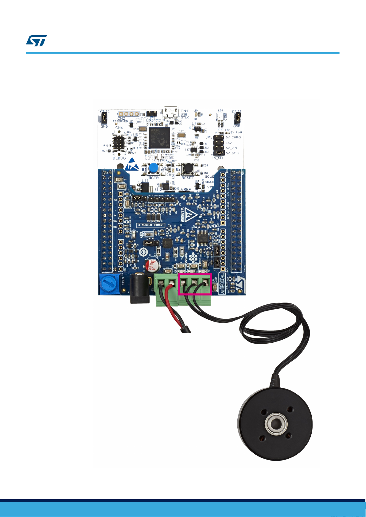
2. Connect the three motor wires U,V,W on the CN1 connector as shown in Figure 4.
Figure 4. Motor connection with X-NUCLEO-IHM16M1
UM2538
UM2538 - Rev 1
page 7/27
Page 8
UM2538
Configure and run the motor control from the STM32 Nucleo motor-control pack
3. Select the jumper configuration on the power board to choose the desired control algorithm (FOC) as
described below:
a. On the NUCLEO-G431RB board, check the jumper settings: JP5 on position [1-2] for 5V_STLK source,
JP8 (VREF) on position [1-2], JP6 (IDD) closed.
b. On the X-NUCLEO-IHM16M1 board
(2)
:
◦ Check jumper settings: J5 closed, J6 closed
◦ For FOC control, set jumper settings as: JP4 and JP7 solder bridge left open, J2 closed on
position [2-3], J3 closed on position [1-2]
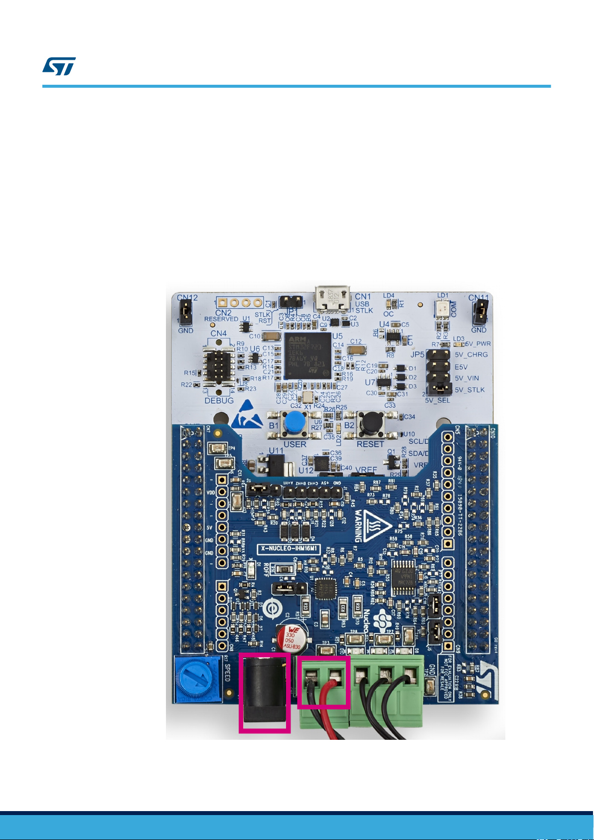
4. Connect the DC power supply (use the power supply provided with the pack or an equivalent one) on CN1
or J4 connector and power-on (up to 12 V DC for the Gimbal motor included in the P-NUCLEO-IHM03 pack,
as shown in Figure 5.
Figure 5. Power-supply connection for X-NUCLEO-IHM16M1
(1)
UM2538 - Rev 1
5. Press the blue button on NUCLEO-G431RB (B1) to start spinning the motor.
page 8/27
Page 9
6. Rotate the potentiometer on X-NUCLEO-IHM16M1 to regulate the motor speed.
1. To supply the NUCLEO-G431RB from the USB, the jumper JP5 must be connected between Pin 1 and Pin 2. For further
details on Nucleo settings refer to [3].
2. Supply voltage must be off before changing the control mode.
4.3 Hardware settings
Table 3 shows the jumper configuration on the X-NUCLEO-IHM16M1 board as shown in Figure 6. According to
the jumper selection, it is possible to choose the 1-shunt or 3-shunt current-sensing mode, the Hall encoder with
pull-up, or the external supply for the NUCLEO-G431RB board.
UM2538
Hardware settings
Table 3. Jumper settings
Jumper Permitted configuration
Default
condition
J5 Selection of the FOC control algorithm. CLOSED
J6 Selection of the FOC control algorithm. CLOSED
JP4 and JP7
J2
Selection of the HW current limiter threshold (disabled in 3-shunt configuration by
default).
J3 Selection of fixed or adjustable current limiter threshold (fixed by default).
(1)
Selection of 1-shunt or 3-shunt configuration (3-shunt by default). OPEN
[2-3]
CLOSED
[1-2]
CLOSED
1. JP4 and JP7 must have both the same configuration: both left open for 3-shunt configuration, both closed for 1- shunt
configuration. On the silkscreen, the correct position for 3- or 1-shunt is indicated together with the default position.
Table 4 shows the main connectors on the X-NUCLEO-IHM16M1 board.
Table 4. Screw terminal table
Screw terminal
J4 Motor power supply input (7 to 45 Vdc)
CN1 3-phase motor connector (U,V,W) and Motor Power Supply input (when J4 is not used)
Function
The X-NUCLEO-IHM16M1 is stacked on ST morpho connectors, male pin headers (CN7 and CN10) accessible
on both sides of the board. They can be used to connect this power board to the NUCLEO-G431RB board. All
signals and power pins for the MCU are available on the ST morpho connectors. For further details refer to the
“ST morpho connectors” section in [3].
UM2538 - Rev 1
Table 5. Connector description
Part reference
CN7, CN10 ST morpho connector
CN5, CN6, CN9, CN8 Arduino Uno connector
U1 STSPIN830 driver
U2 TSV994IPT op. amp.
J4 Power-supply jack connector
J5, J6 Jumpers for FOC use
SPEED Potentiometer
CN1 Motor- and power-supply connector
Description
page 9/27
Page 10

Part reference Description
J1 Hall-encoder sensor connector
J2, J3 Current limiter use and configuration
JP3 External pull-up for sensors
JP4, JP7 Current measure mode (1 shunt / 3 shunt)
D1 LED status indicator
Figure 6. X-NUCLEO-IHM16M1 connectors
UM2538
Upload the firmware example
JP3
D1
J2
J3
J1
U2U1
J4
4.4 Upload the firmware example
The example for the motor-control application example is pre-loaded in the NUCLEO-G431RB board. This
example is using the FOC (field-oriented control) algorithm. This chapter describes the procedure to reload the
firmware demonstration inside the NUCLEO-G431RB board and restart by the default condition. There are two
ways to do it:
• Drag-and-drop procedure (suggested), as detailed in Section 4.4.1
UM2538 - Rev 1
J5 & J6CN1
page 10/27
Page 11

• Through the STM32CubeProgrammer (STM32CubeProg) tool (free download available from
STMicroelectronics web site: www.st.com), as shown in Section 4.4.2
4.4.1 Drag-and-drop procedure
1. Install the ST-LINK drivers from the www.st.com website.
2. On the NUCLEO-G431RB board, set the JP5 jumper in position U5V.
3. Plug the NUCLEO-G431RB board to the host PC using a Type-A to Micro-B USB cable. If the ST-LINK
driver is correctly installed, it is recognized as an external memory device called “NUCLEO” or any similar
name.
4. Drag and drop the binary file of the firmware demonstration (P-NUCLEO-IHM003.out) into the “NUCLEO”
device, listed inside the list of the disk drives (click on the Start button of Windows®), contained into the X-
CUBE-SPN7 firmware pack.
5. Wait until the programming is complete.
4.4.2 STM32CubeProgrammer tool
1. Open the STM32CubeProgrammer tool (STM32CubeProg).
2. Connect the NUCLEO-G431RB board to the PC with a USB Type-A to Micro-B cable through the USB
connector (CN1) on the NUCLEO-G431RB board.
3. Open either the Potentiometer.out or Potentiometer.hex file as the code to be downloaded. The
corresponding window appears as shown in Figure 7.
UM2538
Upload the firmware example
Figure 7. STM32CubeProgrammer tool
4. Click on the Download button (refer to Figure 8).
UM2538 - Rev 1
page 11/27
Page 12

Figure 8. STM32CubeProgrammer download
UM2538
Demonstration usage
4.5
5. Press the Reset button (B2) on the NUCLEO-G431RB board to start using the motor.
Demonstration usage
This section describes how to use the setup to spin the motor:
1. Press the Reset button (black) (NUCLEO-G431RB board)
2. Press the User button (blue) to start the motor (NUCLEO-G431RB board)
3. Check that the motor starts spinning and LEDs D8, D9, and D10 are turned on (X-NUCLEO-IHM16M1
board)
4. Rotate the User rotary knob (blue) clockwise to the maximum (X-NUCLEO-IHM16M1 board)
5. Check that the motor is stopped and LEDs D8, D9, and D10 are turned off (X-NUCLEO-IHM16M1 board)
6. Rotate the User rotary knob (blue) counterclockwise to the maximum (X-NUCLEO-IHM16M1 board)
7. Check that the motor is spinning at a higher speed compared to step 3 and LEDs D8, D9, and D10 are
turned on (X-NUCLEO-IHM16M1 board)
8. Rotate the User rotary knob (blue) to 1/3 of its maximum (X-NUCLEO-IHM16M1 board)
9. Check that the motor is spinning at a lower speed compared to step 7 and LEDs D8, D9, and D10 are
turning on (X-NUCLEO-IHM16M1 board)
10. Press the User button (blue) to stop the motor (NUCLEO-G431RB board)
11. Check that the motor is stopped and LEDs D8, D9, and D10 are turning off (X-NUCLEO-IHM16M1 board)
UM2538 - Rev 1
page 12/27
Page 13

FOC control algorithm settings (advanced user)
5 FOC control algorithm settings (advanced user)
The P-NUCLEO-IHM03 pack supports the ST FOC library. No hardware modification is needed to run the motor
provided in a 3-shunt current-sensing mode. To use the FOC in a 1-shunt configuration, the user must reconfigure
the X-NUCLEO-IHM16M1 board to select the 1-shunt current sensing and the current-limiter features according to
the jumper settings as given in Table 3. Jumper settings. The MC SDK installation is required to reconfigure the P-
NUCLEO-IHM03 project for 1-shunt current sensing, generation, and use.
For further information about the MC SDK, refer to [5].
UM2538
UM2538 - Rev 1
page 13/27
Page 14

UM2538
Electrical schematics
6 Electrical schematics
This chapter presents some of the X-NUCLEO-IHM16M1 schematics related to the material detailed in the user
manual:
• Figure 9. X-NUCLEO-IHM16M1 motor driver connections
• Figure 10. X-NUCLEO-IHM16M1 current-sensing conditioning circuit
• Figure 11. X-NUCLEO-IHM16M1 sensors and shunt resistor circuit
• Figure 12. X-NUCLEO-IHM16M1 L6230 driver and BEMF detection circuit
• Figure 13. X-NUCLEO-IHM16M1 MCU pin assignment
Note: Users are advised to check for the most up-to-date schematics of X-NUCLEO-IHM16M1 and NUCLEO-G431RB
on STMicroelectronics www.st.com web site.
UM2538 - Rev 1
page 14/27
Page 15

X-NUCLEO-IHM16M1 X-NUCLEO-IHM16M1 s che ma tic diagra ms ve rs ion 1| s hee t 1
39K539K
C1
19
INU/INUH
20
0R
+
39K
SENSEV
14
STBY
39K
17
D1
INV
VDD
OUTW
12
1
R7
ENW
61300311121
2
SENSEW
R9
EN_FAULT
MODE
18
ENV
OUTU
NC
8
+
C2
R5
23
INW/INWH
OUTW
M5
R11
3
10
C5
RED
NP
OUTU
21
INV/INVH
22
VDD
VREF
P-MOS
INU
24
ENW/INWL
STSPIN830
13
4.7NF
NP
OUTV
11
1K
SENSEU
7
INW
R4
ENV/INVL
39K
1
TOFF
SENSEV
U1
C4
2.2NF
R30
C6
330R
R32
NP
VS
9
GND
15
33µF 50V
R2
12K
C3
VDD
G
R8
39K
330NF
R6
VDD
33µF 50VNP
R10
SENSEU
VREF
2
TOFF
EPAD
25
SNS
4
ENU/INUL
STBY
16
R1
S
2
VS
Jumper M5 connected
between J2 pin 2&3
VS
39K
EN_FAULT
10NF
1
ENU
J2
6
GND
GND
3
39K
R12
OUTV
Q1
NX3008PBKW
D
3
SENSEW
R3
VS
UM2538 - Rev 1
Figure 9. X-NUCLEO-IHM16M1 motor driver connections
page 15/27
Electrical schematics
UM2538
Page 16

X-NUCLEO-IHM16M1 X-NUCLEO-IHM16M1 s che ma tic diagra ms ve rs ion 1| s hee t 3
OUT
2.2K
R65
Jumper M8 connected
between J6 pin 1&2
IN+
VDD
J5
M8
680R
5
IN+
C14
Jumper M7 connected
between J5 pin 1&2
12
VDD
IN-
6
2
2.2K
R70
0.33R
1/2W
1206
680R
GND
8
U2B
OP303_V
SENSEU
680PF
R60
11
OPEN
TSV994
R62
Vcc
4
1
2
11
OP303_W
R56
2.2K
1
2.2K
OUT
R63
0.33R
1/2W
2.2K
R72
VDD
2.2K
SENSEV
1
GND
11
R58
U2C
C19
3
IN+
10NF
Curr_fdbk3
2.2K
7
1206
680R
J6
OUT
VDD
TSV994
Vcc
4
Curr_fdbk2
GND
11
2.2K
R66
M7
R57
0.33R
1/2W
TSV994
2.2K
R64C17
U2A
Vcc
4
NP
C16
61300211121
R67
VDD
Curr_fdbk1
13
14
1
IN+
10
OPEN
GND
2.2K
R71
2
IN-
R55
JP7
U2D
TSV994
4
Vcc
C20
C15
SENSEW
1206
1
2
OP303_U
61300211121
JP4
OUT
IN-
2
680PF
R59
680PF
R68
VDD
VDD
C18
NP
9
IN-
NP
UM2538 - Rev 1
Figure 10. X-NUCLEO-IHM16M1 current-sensing conditioning circuit
page 16/27
Electrical schematics
UM2538
Page 17

39K539K
19
INU/INUH
20
0R
39K
SENSEV
14
STBY
39K
17
D1
INV
OUTW
12
1
R7
ENW
61300311121
2
SENSEW
R9
EN_FAULT
MODE
18
ENV
OUTU
NC
8
R5
23
INW/INWH
OUTW
M5
R11
3
10
C5
RED
NP
OUTU
21
INV/INVH
22
VDD
VREF
P-MOS
INU
24
ENW/INWL
STSPIN830
13
4.7NF
NP
OUTV
11
1K
SENSEU
7
INW
R4
ENV/INVL
39K
1
TOFF
SENSEV
U1
C4
2.2NF
R30
C6
330R
R32
NP
VS
9
GND
15
12K
G
R8
39K
R6
R10
SENSEU
VREF
2
TOFF
EPAD
25
SNS
4
ENU/INUL
STBY
16
R1
S
2
Jumper M5 connected
between J2 pin 2&3
39K
10NF
1
ENU
J2
6
GND
GND
3
39K
R12
OUTV
Q1
NX3008PBKW
D
3
SENSEW
R3
VS
Figure 1: X-NUCLEO-IHM16M1 c ircuit s ch e matic (1 o f 5)
A+/H1
B+/H2
Z+/H3
+5V
GND
Roff
VDD
SPEED
VREF
VDD
VDD
VDD
5V
5V
VS
VS VDD
VDD
VREF
CURRENT_REF
TOFF
SPEED
H1
H2
H3
VBUS NTC
TP5
1
330R
R17
10K
1 3
2
R22
3K
NTC
R38
X7R
R21
3K
R13
3.9K
JP3
1
CLOSE
2
R28
4.7K
NP
C12
10PF
D3
3V
1
61300511121
1
2
3
4
5
R18
10K
R14
180K
1%
C9
220NF
16V
X7R
R26
4.7K
NP
C22
220NF
16V
X7R
R16
12K
TP2
1
S1751-46R
J3
13
2
61300311121
D2
3V
22K
C21
100NF
50V
X7R
R24 330R
D4
3V
R20
3K
TP3
1
S1751-46R
M6
TP1
1
R25 330R
C11
10PF
C7
220NF
16V
X7R
Jumper M6 connected
between J3 pin 1&2
S1751-46R
R23
10PF
R27
4.7K
NP
S1751-46R
C10
C8
NCP18WB473J03RB
220NF
16V
MMSZ3V0T1G
TP4
GND
GND
VS
J1
S1751-46R
R15
MMSZ3V0T1G
R19
MMSZ3V0T1G
12K
1%
UM2538 - Rev 1
Figure 11. X-NUCLEO-IHM16M1 sensors and shunt resistor circuit
page 17/27
Electrical schematics
UM2538
Page 18

OP303_W
8
7
6
5
4
3
2
1
ESQ-119-24-G-D
25
R83
R440R
2
4
6
8
10
5V
27
27
INV
C7_32
X7R
C10_24
C10_11
BEMF3
R45
GU_4xx
R75
NP
C10_14
STBY
23
C10_15
M2
CN5 NP
24
26
0R
17
38
VDD
29
0R
ENV
26
28
30
BEMF1
NP
1
2
3
4
5
6
7
8
12
24
OPTICAL_TARGET
C10_18
C10_26
INW
STBY
REF
INU
INV
VDD
5V
GND
GND
bemf1
bemf3
bemf2
SPD
18
CN9 NP
C10_19
ESQ-119-24-G-D
BEMF2
C10_30
31
SSQ-108-01-F-S
13
C10_2
R77
ENU
28
30
33
35
22
33
C10_28
19
C10_30
C10_13
INW
SSQ-110-01-F-S
OPTICAL_TARGET
CN10
1
3
5
7
9
11
CN6 NP
35
37
20
PA8 - INU
PA9 - INV
PA10 - INW
PC1 - ADC
PC3 - ADC
PC2
PB5
PC9 - GPIO
<CURRENT_REF>
C10_16
C7_28
31 32
34
14
R78
21
36
C10_6
R79
16
SSQ-106-01-F-S
1
3
5
7
9
NP
37
C7_34
34
C10_28
18
R80
CN7
13
36
INU
M1
19
21
29
10
12
38
2
4
6
8
10
NTC
CN8
22
C10_31
14
16
32
20
C7_17
OP303_V
C10_18
15
C10_11
17
23
OPTICAL_TARGET
C13
220NF
16V
R76
SSQ-108-01-F-S
NP
C10_15
11
C10_34
OP303_U
1
2
3
4
5
6
SPEED
C10_30
C10_25
F302
F302
PB0
PB13
PB11
PB13
PA7
M4
R74
C10_4
15
25
VDD
C10_18
PB13
PB14
F303 (Embedded OPAMP ONLY)
PA6
F302
STM32F303 Embedded OPAMP
C10_13
IO_BEMF
C7_30
C10_27
M3
C7_34
9
8
7
6
5
4
3
2
1
PC0 - ADC
NP
NP
NP
NP
Figure 3: X-NUCLEO-IHM16M1 c ircuit s ch e matic (3 o f 5)
CN3
D6
1
S1751-46R
D9
D12
OUT V
CN1
YELLOW
R49
10K
BEMF3
OUTU
1/4W
1
BEMF2
691311500105
BAT30KFILM
BAT30KFILM
BAT30KFILM
VS
VDD
IO_BEMF
S1751-46R
R53
VS
YELLOW
TP8
10K 1/4W
2.2K
R46
3
BAT30KFILM
R50
10K
2
VS
GND
OUT W
OUT U
D11
805-1699
D8
S1751-46R
1
691351500002
R47
1
1
J4
RS
FC681465P
1/4W
10K 1/4W
YELLOW
1/4W
TP6
691351500003
BAT30KFILM
R54
OUTW
1
3
2
OUTV
2.2K
D7
10K 1/4W
R48
3
R51
10K
D10
BEMF1
D13
2.2K
1
D5
4
CN2
TP7
2
BAT30KFILM
R52
2
5
UM2538 - Rev 1
Figure 12. X-NUCLEO-IHM16M1 L6230 driver and BEMF detection circuit
page 18/27
Electrical schematics
UM2538
Page 19

X-NUCLEO-IHM16M1 X-NUCLEO-IHM16M1 s che ma tic diagra ms ve rs ion 1| s hee t 2
OP303_W
8
7
6
5
4
3
2
1
ESQ-119-24-G-D
25
R88
R83
R440R
2
4
6
8
10
5V
27
C10_34
27
INV
C7_32
X7R
C10_24
C10_11
BEMF3
C10_18
F303
F302
BKIN2 (F302, F303)
CURRENT_REF
R45
GU_4xx
R75
NP
C10_14
STBY
23
C10_15
M2
CN5 NP
24
26
R69
0R
17
38
R33
R84
VDD
29
C7_34
0R
ENV
26
28
30
BEMF1
PB14
NP
R40
H3
1
2
3
4
5
6
7
8
C10_16
12
24
OPTICAL_TARGET
R35
C10_18
C10_26
0R
INW
STBY
REF
INU
INV
VDD
5V
GND
GND
bemf1
bemf3
bemf2
SPD
18
CN9 NP
C10_19
ESQ-119-24-G-D
BEMF2
C10_30
31
0R
C10_26
SSQ-108-01-F-S
H1
13
C10_15
C10_2
R77
C10_4
ENU
0R
0R
28
30
33
35
22
33
C10_19
C10_14
VBUS
C10_28
0R
19
EN_FAULT
C10_30
C10_13
R87
C10_27
INW
R85
SSQ-110-01-F-S
OPTICAL_TARGET
CN10
1
3
5
7
9
11
R81
R43
CN6 NP
35
37
20
C7_17
PA8 - INU
PA9 - INV
PA10 - INW
PC1 - ADC
PC3 - ADC
PC2
PB5
PC9 - GPIO
<CURRENT_REF>
C10_16
0R
C7_28
31 32
34
14
R78
21
36
C10_6
R79
R31
16
0R
SSQ-106-01-F-S
1
3
5
7
9
R36
0R
NP
37
C7_34
C7_30
34
C10_28
C7_28
18
R80
C10_31
CN7
Curr_fdbk2
13
36
0R
0R
INU
M1
19
21
29
10
R82
12
38
2
4
6
8
10
R29
R86
NTC
CN8
22
C10_31
R42
C10_25
0RR73
14
16
32
20
R39
NP
C10_2
C7_17
OP303_V
C10_18
R41
15
R61
C10_11
17
23
Curr_fdbk1
Curr_fdbk3
C10_6
OPTICAL_TARGET
C13
220NF
16V
R76
SSQ-108-01-F-S
NP
R34
0R
R37
C10_15
11
C10_34
OP303_U
ENW
1
2
3
4
5
6
SPEED
C10_30
C10_28
C10_25
C7_32
PB0 - PhW Sense
F303
PA7 - PhW Sense
PB10 - H3
PA15 - H1
F030PC6 - H1
F302
F302
F302
PB0
PB3 - H2
PB13
PB11
PB13
PB14
PB15
PA7
M4
R74
NP
C10_4
15
25
VDD
C10_18
PB13
PB14
PB15
F303 (Embedded OPAMP ONLY)
PB1 - PhV Sense
PC7 - H2 F030
PWM
DAC
F030
PB11 - PhV Sense
PA4 - DAC
PB4 - PWM
PC8 - H3
PC4
PA6
PA1 - PhU Sense
PC5
PA0
PA11 - BKIN2
F302
PB12 - BKIN
STM32F303 Embedded OPAMP
C10_13
H2
IO_BEMF
C7_30
C10_27
M3
C7_34
C10_24
C10_15
9
8
7
6
5
4
3
2
1
PC0 - ADC
0R
0R
NP
NP
NP
NP
0R
0R
0R
0R
0R
NP
UM2538 - Rev 1
Figure 13. X-NUCLEO-IHM16M1 MCU pin assignment
page 19/27
Electrical schematics
UM2538
Page 20

7 References
Table 6 lists STMicroelectronics related documents available at www.st.com for supplementary information.
ID Reference document
[1]
[2]
[3] STM32G4 Nucleo-64 boards (MB1367) user manual (UM2505).
[4] Compact and versatile three-phase and three-sense motor driver datasheet (DS12584).
[5] STM32 MC SDK software expansion for STM32Cube data brief (DB3548).
[6] Getting started with STM32 motor control SDK v5.0 user manual (UM2374).
Getting started with the X-NUCLEO-IHM16M1 three-phase brushless motor driver board based on
STSPIN830 for STM32 Nucleo user manual (UM2415).
Getting started with the X-CUBE-SPN16 three-phase brushless DC motor driver software expansion for
STM32Cube user manual (UM2419).
UM2538
References
Table 6. STMicroelectronics reference documents
UM2538 - Rev 1
page 20/27
Page 21

Federal Communications Commission (FCC) and Industry Canada (IC) Compliance Statements
Appendix A Federal Communications Commission (FCC) and Industry
Canada (IC) Compliance Statements
A.1 FCC Compliance Statement
Part 15.19
This device complies with Part 15 of the FCC Rules. Operation is subject to the following two conditions: (1) this
device may not cause harmful interference, and (2) this device must accept any interference received, including
interference that may cause undesired operation.
Part 15.21
Any changes or modifications to this equipment not expressly approved by STMicroelectronics may cause
harmful interference and void the user's authority to operate this equipment.
Part 15.105
This equipment has been tested and found to comply with the limits for a Class B digital device, pursuant to part
15 of the FCC Rules. These limits are designed to provide reasonable protection against harmful interference in a
residential installation. This equipment generates uses and can radiate radio frequency energy and, if not installed
and used in accordance with the instruction, may cause harmful interference to radio communications. However,
there is no guarantee that interference will not occur in a particular installation. If this equipment does cause
harmful interference to radio or television reception which can be determined by turning the equipment off and on,
the user is encouraged to try to correct interference by one or more of the following measures:
• Reorient or relocate the receiving antenna.
• Increase the separation between the equipment and receiver.
• Connect the equipment into an outlet on circuit different from that to which the receiver is connected.
• Consult the dealer or an experienced radio/TV technician for help.
Note: Use only shielded cables.
UM2538
A.2
Responsible party (in the USA)
Terry Blanchard
Americas Region Legal | Group Vice President and Regional Legal Counsel, The Americas
STMicroelectronics, Inc.
750 Canyon Drive | Suite 300 | Coppell, Texas 75019
USA
Telephone: +1 972-466-7845
IC Compliance Statement
This device complies with FCC and Industry Canada RF radiation exposure limits set forth for general population
for mobile application (uncontrolled exposure). This device must not be collocated or operating in conjunction with
any other antenna or transmitter.
Compliance Statement
Notice: This device complies with Industry Canada licence-exempt RSS standard(s). Operation is subject to the
following two conditions: (1) this device may not cause interference, and (2) this device must accept any
interference, including interference that may cause undesired operation of the device.
Industry Canada ICES-003 Compliance Label: CAN ICES-3 (B) / NMB-3 (B).
Déclaration de conformité
Avis: Le présent appareil est conforme aux CNR d'Industrie Canada applicables aux appareils radio exempts de
licence. L'exploitation est autorisée aux deux conditions suivantes : (1) l'appareil ne doit pas produire de
brouillage, et (2) l'utilisateur de l'appareil doit accepter tout brouillage radioélectrique subi, même si le brouillage
est susceptible d'en compromettre le fonctionnement.
UM2538 - Rev 1
page 21/27
Page 22

Étiquette de conformité à la NMB-003 d'Industrie Canada : CAN ICES-3 (B) / NMB-3 (B).
UM2538
IC Compliance Statement
UM2538 - Rev 1
page 22/27
Page 23

Revision history
UM2538
Table 7. Document revision history
Date Version Changes
19-Apr-2019 1 Initial release.
UM2538 - Rev 1
page 23/27
Page 24

UM2538
Contents
Contents
1 Features ...........................................................................2
2 Ordering information ..............................................................3
2.1 Product marking ...............................................................3
2.2 Codification ...................................................................3
3 Development environment .........................................................4
3.1 System requirements ...........................................................4
3.2 Development toolchains .........................................................4
3.3 Demonstration software .........................................................4
4 Getting started (basic user) ........................................................5
4.1 System architecture ............................................................5
4.2 Configure and run the motor control from the STM32 Nucleo motor-control pack .........5
4.3 Hardware settings ..............................................................9
4.4 Upload the firmware example ...................................................10
4.4.1 Drag-and-drop procedure .................................................11
4.4.2 STM32CubeProgrammer tool ..............................................11
4.5 Demonstration usage ..........................................................12
5 FOC control algorithm settings (advanced user)...................................13
6 Electrical schematics .............................................................14
7 References .......................................................................20
Appendix A Federal Communications Commission (FCC) and Industry Canada (IC)
Compliance Statements...........................................................21
A.1 FCC Compliance Statement ....................................................21
A.2 IC Compliance Statement ......................................................21
Revision history .......................................................................23
Contents ..............................................................................24
List of tables ..........................................................................25
List of figures..........................................................................26
UM2538 - Rev 1
page 24/27
Page 25

UM2538
List of tables
List of tables
Table 1. List of available products...............................................................3
Table 2. Nucleo-board codification explanation......................................................3
Table 3. Jumper settings .....................................................................9
Table 4. Screw terminal table..................................................................9
Table 5. Connector description.................................................................9
Table 6. STMicroelectronics reference documents ..................................................20
Table 7. Document revision history............................................................. 23
UM2538 - Rev 1
page 25/27
Page 26

UM2538
List of figures
List of figures
Figure 1. P-NUCLEO-IHM03 pack .............................................................1
Figure 2. Four-block architecture of the P-NUCLEO-IHM03 pack ........................................5
Figure 3. X-NUCLEO-IHM16M1 and NUCLEO-G431RB assembled ......................................6
Figure 4. Motor connection with X-NUCLEO-IHM16M1 ...............................................7
Figure 5. Power-supply connection for X-NUCLEO-IHM16M1 ..........................................8
Figure 6. X-NUCLEO-IHM16M1 connectors ......................................................10
Figure 7. STM32CubeProgrammer tool ......................................................... 11
Figure 8. STM32CubeProgrammer download..................................................... 12
Figure 9. X-NUCLEO-IHM16M1 motor driver connections ............................................15
Figure 10. X-NUCLEO-IHM16M1 current-sensing conditioning circuit ..................................... 16
Figure 11. X-NUCLEO-IHM16M1 sensors and shunt resistor circuit ...................................... 17
Figure 12. X-NUCLEO-IHM16M1 L6230 driver and BEMF detection circuit ................................. 18
Figure 13. X-NUCLEO-IHM16M1 MCU pin assignment ............................................... 19
UM2538 - Rev 1
page 26/27
Page 27

UM2538
IMPORTANT NOTICE – PLEASE READ CAREFULLY
STMicroelectronics NV and its subsidiaries (“ST”) reserve the right to make changes, corrections, enhancements, modifications, and improvements to ST
products and/or to this document at any time without notice. Purchasers should obtain the latest relevant information on ST products before placing orders. ST
products are sold pursuant to ST’s terms and conditions of sale in place at the time of order acknowledgement.
Purchasers are solely responsible for the choice, selection, and use of ST products and ST assumes no liability for application assistance or the design of
Purchasers’ products.
No license, express or implied, to any intellectual property right is granted by ST herein.
Resale of ST products with provisions different from the information set forth herein shall void any warranty granted by ST for such product.
ST and the ST logo are trademarks of ST. For additional information about ST trademarks, please refer to www.st.com/trademarks. All other product or service
names are the property of their respective owners.
Information in this document supersedes and replaces information previously supplied in any prior versions of this document.
© 2019 STMicroelectronics – All rights reserved
UM2538 - Rev 1
page 27/27
 Loading...