How it Works
Log In / Sign Up
Buy Points
How it Works
FAQ
Contact Us
Questions and Suggestions
Users
ST
Loading...
V
VNB49N04
VND05B
VND05BSP
VND10N06
VND10N06-1
VND14NV04
VND14NV04-1
VND1NV04
VND3NV04
VND3NV04-1
VND5004A-E
VND5004ASP30-E
VND5004B-E
VND5004BSP30-E
VND5012AK-E
VND5025AK-E
VND5025LAK-E
VND5050AJ-E
VND5050AK-E
VND5050J-E
VND5050K-E
VND5160AJ-E
VND5160J-E
VND5E004A-E
VND5E004ASP30-E
VND5E006ASP-E
VND5E008AY-E
VND5E008MY-E
VND5E012AY-E
VND5E012MY-E
VND5E025AK-E
VND5E025AS-E
VND5E025BK-E
VND5E025LK-E
VND5E025MK-E
VND5E050AJ-E
VND5E050AK-E
VND5E050ASO-E
VND5E050J-E
VND5E050K-E
VND5E050MCJ-E
VND5E050MCK-E
VND5E050MJ-E
VND5E050MK-E
VND5E160AJ-E
VND5E160ASO-E
VND5E160J-E
VND5N07
VND5T016ASP-E
VND5T035AK-E
VND5T050AK-E
VND5T100AJ-E
VND600
VND600P-E
VND600SP
VND600SP-E
VND7N04
VND7N04-1
VND7NV04
VND7NV04-1
VND810
2
VND810-E
VND810MSP
VND810MSP-E
VND810P-E
VND810PEP-E
VND810SP
VND830AEP-E
VND830ASP
VND830ASP-E
VND830E-E
VND830LSP
2
VND830LSP-E
VND830MSP
VND830MSP-E
VND830P-E
VND830PEP-E
VND830SP
VND830SP-E
VND920
VND920P-E
VNH2SP30-E
VNH3ASP30-E
VNH3SP30-E
VNH5019A-E
VNH5050A-E
VNH5180A-E
VNH7013XP-E
VNI2140J
VNI4140K
VNI4140K-32
VNI8200XP
2
VNK14N04FM
VNK7N04FM
VNL5050N3-E
VNL5050S5-E
VNL5090N3-E
VNL5090S5-E
VNL5160N3-E
VNL5160S5-E
Loading...
Loading...
Nothing found
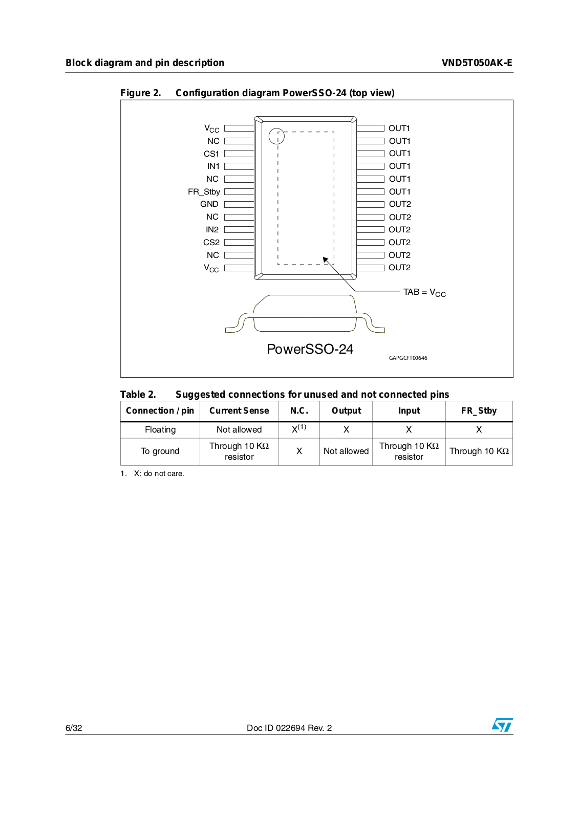
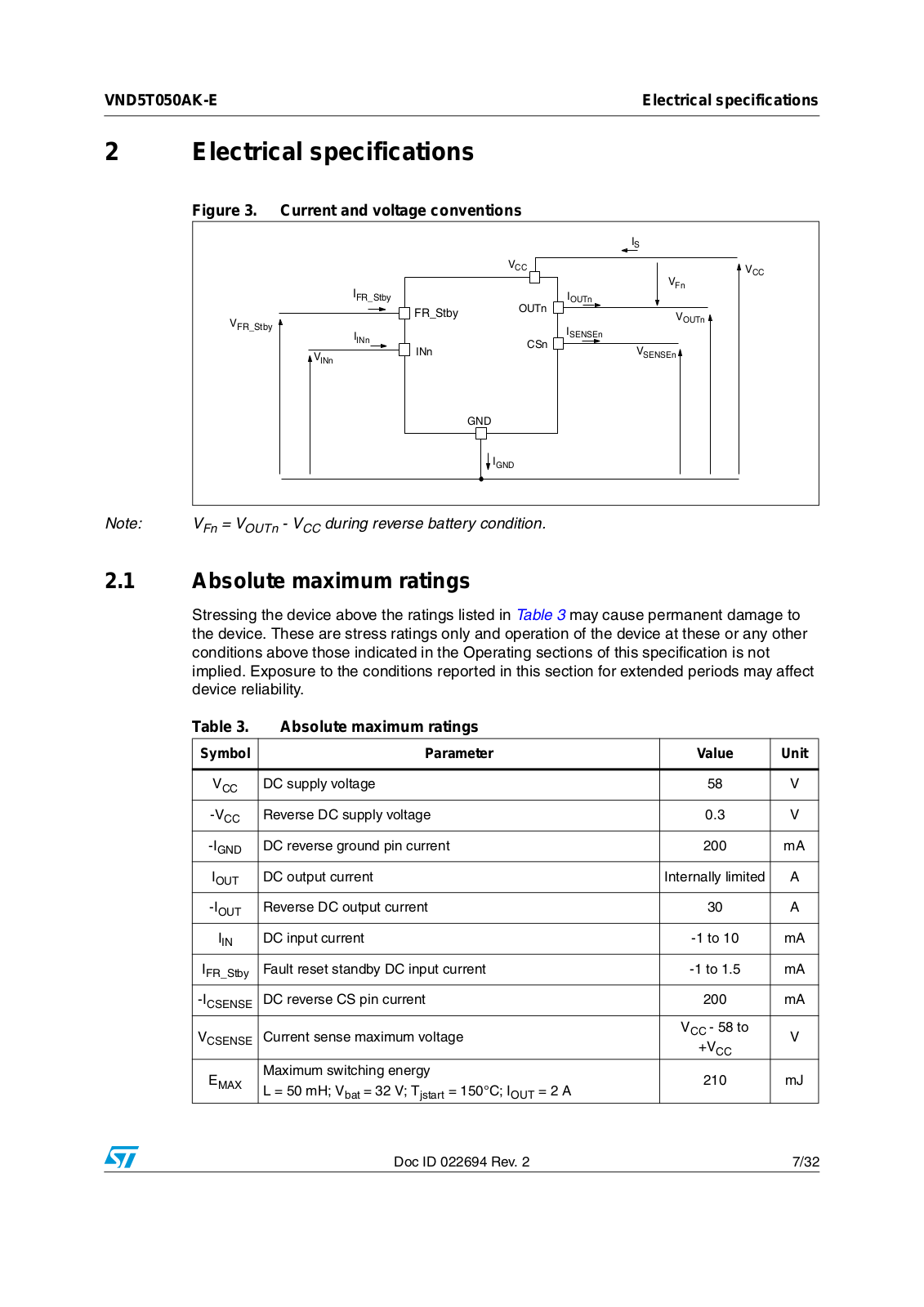
VND5T050AK-E
User Manual
32 pgs
810.91 Kb
0
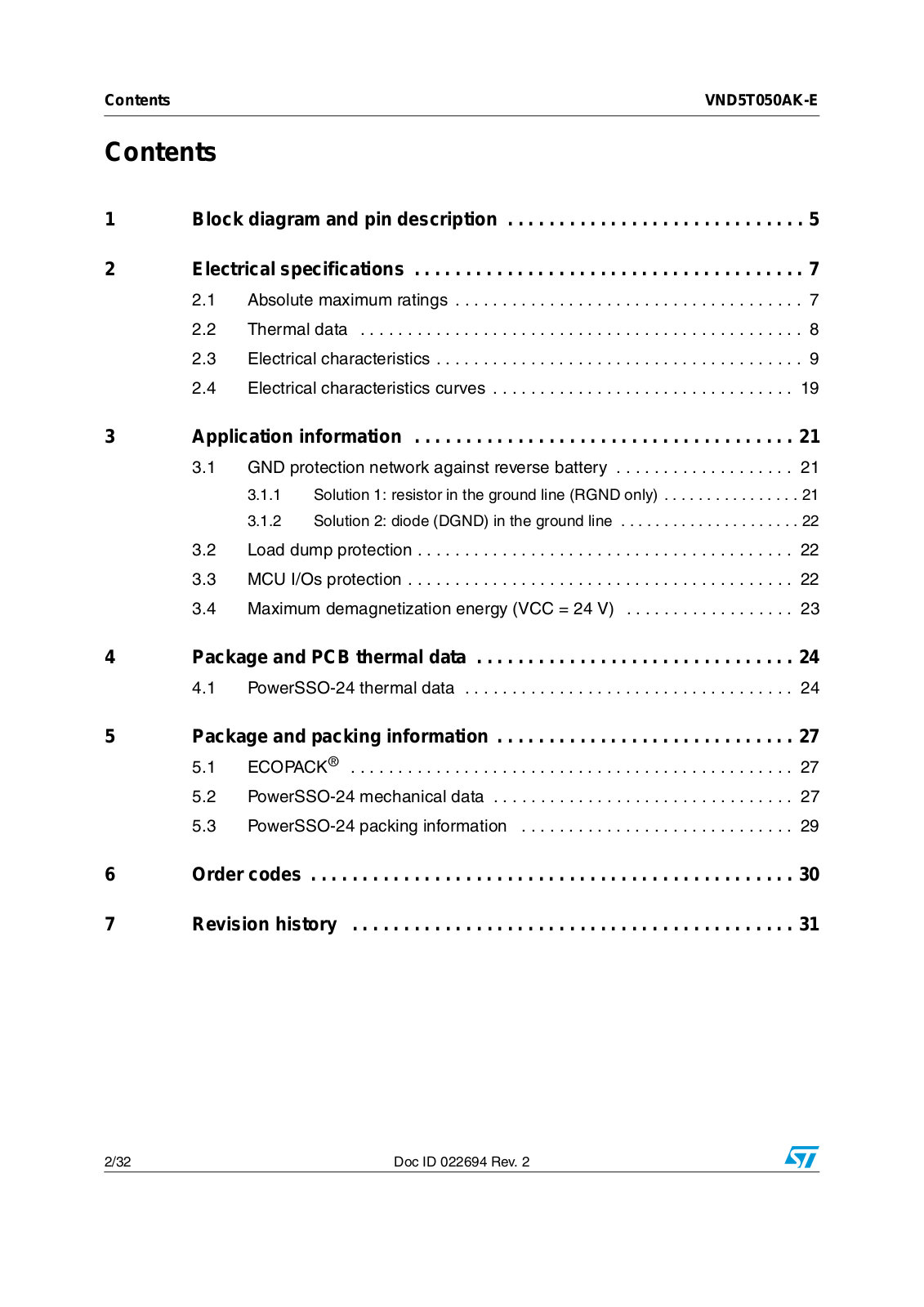
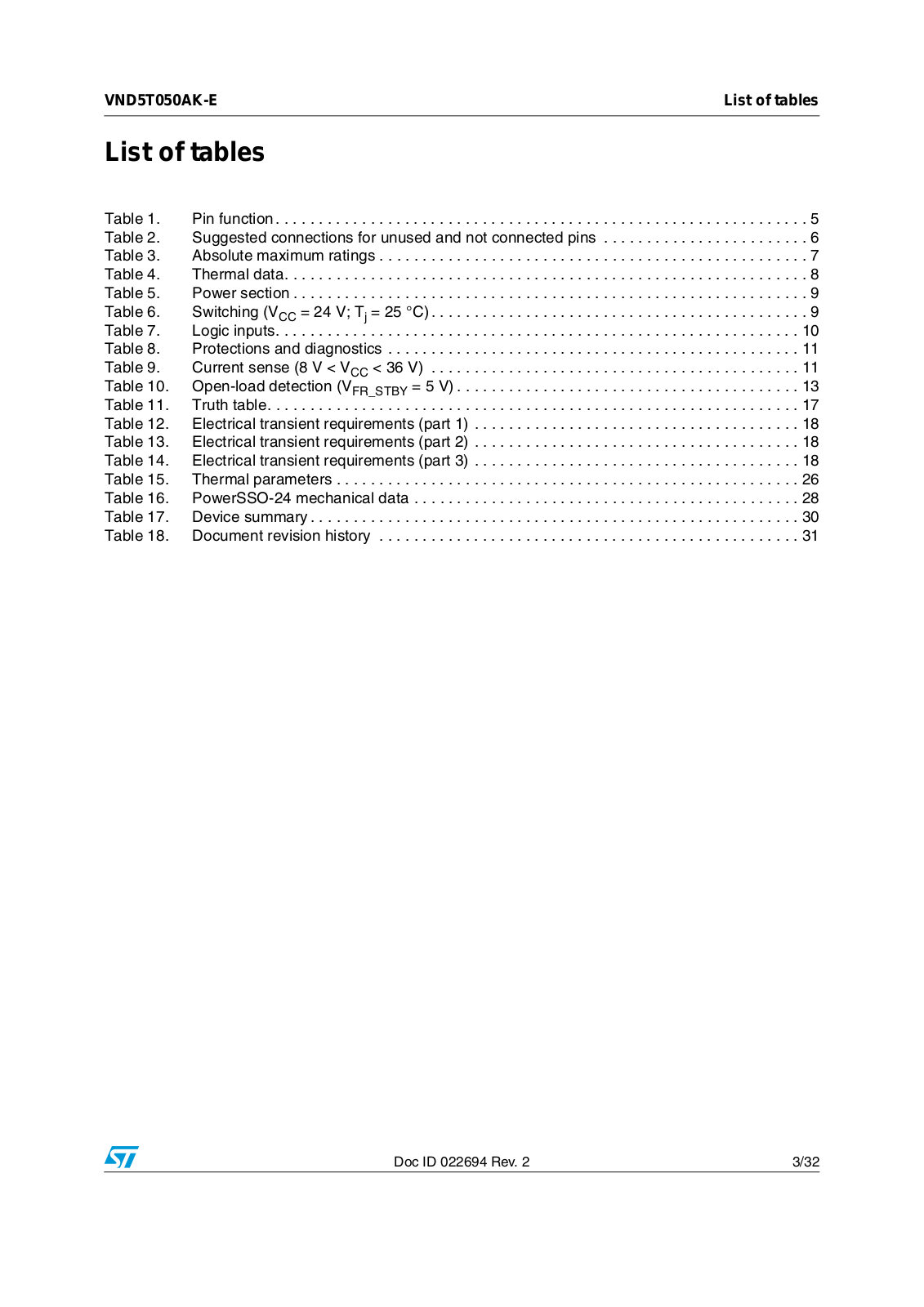
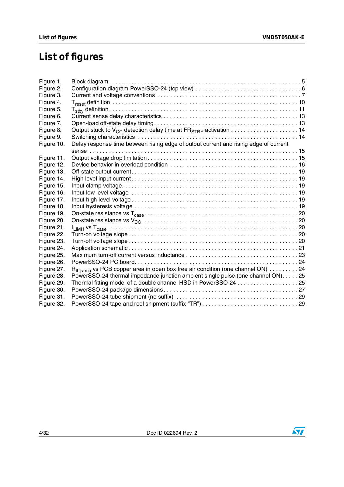
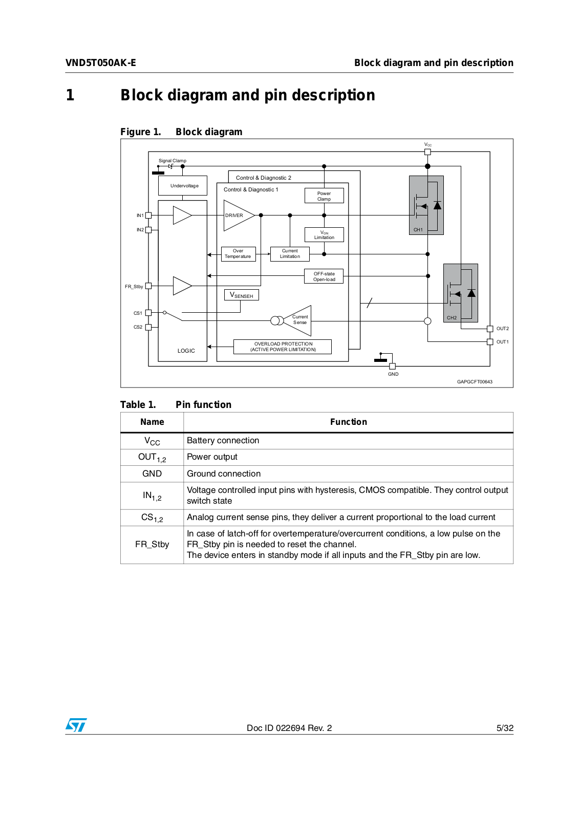
Table of contents
Loading...
ST VND5T050AK-E User Manual
...
ST User Manual
Download
Specifications and Main Features
Frequently Asked Questions
User Manual
Download
Loading...
+
22
hidden pages
Unhide
You need points to download manuals.
1 point = 1 manual.
You can buy points or you can get point for every manual you upload.
Buy points
Upload your manuals
 Loading...