

Page 1

April 2007 Rev 1 1/27
UM0408
User manual
Security door keypad controller
Introduction
This document describes the operation of a keypad controller for use in security door
applications. The aim is to assist in the development of a keypad decoding system and to
display associated information through LEDs for all necessary actions such as power on,
door open and error. The entire system has been developed to target low-end and low-cost
application areas and has been realized with the help of the ST7FLITE39 microcontroller. A
useful additional feature is the support of system protection from physical intrusion, using
the STM1403.
The associated evaluation board (order code STEVAL-IAS001V1) aims to display the
capabilities of ST's general purpose microcontroller to fit the market segment of home
automation and security, keeping the system cost as low as possible.
The board can operate in 2 modes:
■ User (stand-alone) mode
■ Administrator mode
– through board
– through PC Graphical User Interface
System operation in the various modes is explained through the document sections. When
the board is connected to the power supply the system enters the user configuration mode.
Administrator mode can be accessed through the use of a PC, where SCI communication is
set up and used between the PC and the board through the RS232.
At the time of manufacturing an additional board has been connected to allow in-circuit
programming of the microcontroller. The two can be easily disconnected so that the keypad
controller for the security door evaluation board can be used independently.
To summarize, the key features of the evaluation board include:
■ 4x3 key matrix
■ 3 LEDs (green for power, red for error and yellow for magnetic lock)
■ 4 jumpers for physical intrusion detection with battery back-up and buzzer
■ On-board SPI EEPROM for event logging
■ On-board RS232 driver to interface with the PC
■ Power supply adaptor (3.4V - 19V)
■ Embedded in-circuit programming capability
www.st.com
Page 2

Contents UM0408
2/27
Contents
1 Getting started . . . . . . . . . . . . . . . . . . . . . . . . . . . . . . . . . . . . . . . . . . . . . . 4
1.1 System requirements . . . . . . . . . . . . . . . . . . . . . . . . . . . . . . . . . . . . . . . . . 4
1.2 Package contents . . . . . . . . . . . . . . . . . . . . . . . . . . . . . . . . . . . . . . . . . . . . 4
1.3 Hardware installation . . . . . . . . . . . . . . . . . . . . . . . . . . . . . . . . . . . . . . . . . 4
1.4 Software installation . . . . . . . . . . . . . . . . . . . . . . . . . . . . . . . . . . . . . . . . . . 6
2 Running the security door application . . . . . . . . . . . . . . . . . . . . . . . . . 10
2.1 User or standalone mode . . . . . . . . . . . . . . . . . . . . . . . . . . . . . . . . . . . . . 10
2.1.1 Powering on the system . . . . . . . . . . . . . . . . . . . . . . . . . . . . . . . . . . . . . 10
2.1.2 Default system settings . . . . . . . . . . . . . . . . . . . . . . . . . . . . . . . . . . . . . 10
2.1.3 Valid user code . . . . . . . . . . . . . . . . . . . . . . . . . . . . . . . . . . . . . . . . . . . 11
2.1.4 Door open . . . . . . . . . . . . . . . . . . . . . . . . . . . . . . . . . . . . . . . . . . . . . . . 11
2.1.5 Physical intrusion . . . . . . . . . . . . . . . . . . . . . . . . . . . . . . . . . . . . . . . . . . 11
2.1.6 Error conditions in user mode . . . . . . . . . . . . . . . . . . . . . . . . . . . . . . . . 11
2.1.7 User-code tampering . . . . . . . . . . . . . . . . . . . . . . . . . . . . . . . . . . . . . . . 12
2.2 Administrator mode through board . . . . . . . . . . . . . . . . . . . . . . . . . . . . . . 12
2.2.1 Add new user code . . . . . . . . . . . . . . . . . . . . . . . . . . . . . . . . . . . . . . . . 12
2.2.2 Delete user code . . . . . . . . . . . . . . . . . . . . . . . . . . . . . . . . . . . . . . . . . . 13
2.3 Administrator password reset through board . . . . . . . . . . . . . . . . . . . . . . 14
2.4 Administrator mode through PC graphical user interface . . . . . . . . . . . . . 15
2.4.1 Connecting to the PC . . . . . . . . . . . . . . . . . . . . . . . . . . . . . . . . . . . . . . . 15
2.4.2 Powering on the board . . . . . . . . . . . . . . . . . . . . . . . . . . . . . . . . . . . . . . 16
2.4.3 The first GUI window - login GUI mode . . . . . . . . . . . . . . . . . . . . . . . . . 16
2.4.4 Communication setting . . . . . . . . . . . . . . . . . . . . . . . . . . . . . . . . . . . . . 16
2.4.5 Communication error . . . . . . . . . . . . . . . . . . . . . . . . . . . . . . . . . . . . . . . 17
2.4.6 Features supported by the GUI . . . . . . . . . . . . . . . . . . . . . . . . . . . . . . . 18
2.4.7 Logoff GUI mode . . . . . . . . . . . . . . . . . . . . . . . . . . . . . . . . . . . . . . . . . . 19
2.4.8 Automatic Logoff from GUI mode (through watchdog) . . . . . . . . . . . . . 19
Appendix A Abbreviations . . . . . . . . . . . . . . . . . . . . . . . . . . . . . . . . . . . . . . . . . . . 20
Appendix B Demonstration board schematic . . . . . . . . . . . . . . . . . . . . . . . . . . . 21
Appendix C Bill of materials . . . . . . . . . . . . . . . . . . . . . . . . . . . . . . . . . . . . . . . . . 22
Page 3

UM0408 Contents
3/27
Appendix D Troubleshooting. . . . . . . . . . . . . . . . . . . . . . . . . . . . . . . . . . . . . . . . . 25
D.1 Communication error. . . . . . . . . . . . . . . . . . . . . . . . . . . . . . . . . . . . . . . . . 25
D.2 Time-out error . . . . . . . . . . . . . . . . . . . . . . . . . . . . . . . . . . . . . . . . . . . . . . 25
D.3 Delete all users . . . . . . . . . . . . . . . . . . . . . . . . . . . . . . . . . . . . . . . . . . . . . 25
3 Revision history . . . . . . . . . . . . . . . . . . . . . . . . . . . . . . . . . . . . . . . . . . . 26
Page 4

Getting started UM0408
4/27
1 Getting started
1.1 System requirements
The system can operate in standalone mode by powering it externally using a power supply
adaptor (3.4V to 19V). For the system to be connected to a PC for administrator use, a
recent version of Windows, such as Windows 2000 or Windows XP must be installed on the
PC.
Note: The version of the Windows OS installed on your PC can be determined by clicking on the
System icon in the Control Panel.
1.2 Package contents
The keypad controller for the security door evaluation package is orderable with the
following order code: STEVAL-IAS001V1. It includes:
● Hardware
– One demonstration board
● Software
– PC executable software to be used along with the demonstration board
● Documentation
–User manual
The firmware source code (C language) is not included in the evaluation package. Please
contact your ST sales office to request it.
1.3 Hardware installation
The demonstration board can be powered through an external power supply using a DC
adaptor (3.4V to 19V). It is not included within the ST evaluation package.
Page 5

UM0408 Getting started
5/27
Figure 1. Security door keypad controller - front view
The major components present on the front of the board are (see Figure 1):
1. An external power jack for the DC adaptor
2. 3 status LEDs for power, error and magnetic lock
3. 4x3 key matrix to enter the user code
4. 4 jumpers for physical intrusion detection
5. An RS232 female socket
6. An HE10 connector for ICC programming
3 status LEDs
External power
RS232 female
HE10 ICC
4x3 key matrix
supply jack
socket
connector
4 jumpers for
physical intrusion
configuration
Page 6

Getting started UM0408
6/27
Figure 2. Security door keypad controller - back view
The major components present on the back of the board are (see Figure 2):
1. A buzzer for physical intrusion detection
2. A coin-type battery as back-up for the tamper detection device in the event of power
failure
3. KF33B voltage regulator
4. ST7LITE39F2 microcontroller
5. M95080 EEPROM for data logging
6. STM1403 tamper detection device
7. ST3232C RS232 driver
1.4 Software installation
To install the PC GUI, follow the steps described below:
1. Double-click the Security Door executable icon. The window shown in Figure 3 opens.
KF33
Battery
STPM1403
ST3232C
M95080
ST7FLite39
Buzzer
Page 7

UM0408 Getting started
7/27
Figure 3. Installation window
2. Click Next to move to the License Agreement window shown in Figure 4. Read the
license and if you accept it, click Yes.
Figure 4. License agreement
3. The Customer Information window opens as shown in Figure 5. Enter the relevant
information and click Next.
Page 8

Getting started UM0408
8/27
Figure 5. Customer Information
4. Now select the folder in which you want to install the software (see Figure 6). By default
the software is installed to the following path:
C:\Program Files\STMicroelectronics\SecurityDoorKeypad
Figure 6. Select installation folder
5. After selecting the destination folder, click Next. The software installation then starts,
see Figure 7.
Page 9

UM0408 Getting started
9/27
Figure 7. Installation process
6. On completion of the installation process, the window shown in Figure 8 opens. Click
the Finish button.
Figure 8. Installation complete
You will find the software and Help Files have been placed in the installation folder. Also, a
shortcut is available in the Windows Start Menu and on the Desktop.
Page 10

Running the security door application UM0408
10/27
2 Running the security door application
2.1 User or standalone mode
2.1.1 Powering on the system
This is an easy-to-use system. As soon as you plug in the DC power supply (3.4V to 19V)
through the adaptor the system is up and running.
All the three status LEDs glow (see Figure 9) until the system stabilizes.
Figure 9. Power-on condition, all LEDs ON
After the around 4-5 seconds, the system stabilizes and just the green power LED remains
on (see Figure 10).
Figure 10. System stable, ready to use
Note: Do not perform any operations while the system is stabilizing (i.e. while all three LEDs glow).
2.1.2 Default system settings
The system comes with a number of default settings including the administrator password,
which is "00000". You are recommended to change this as soon as the system is functional
(refer to the GUI help).
ON ON ON
ON
Page 11

UM0408 Running the security door application
11/27
2.1.3 Valid user code
A valid user code is 5-digit long. You cannot use "00000" as a code; it is reserved for the
system default setting.
A total of 49 user codes are supported by the system.
2.1.4 Door open
Each valid user code entry is presented by the magnetic lock LED (yellow) glowing (see
Figure 11). The door remains open for approximately 15 seconds.
If another command is issued during the door open condition, the new command will
override and the system will perform accordingly.
All these events are logged in the EEPROM and can be seen through the GUI.
Figure 11. Door open condition
2.1.5 Physical intrusion
The system has been designed to detect physical tampering. Four jumpers have been
provided on the board that determine the tamper condition.
● Normal or no tampering condition
This is the default status, when both the NL jumpers (JP2, JP4) are closed and both the
NH jumpers (JP1, JP3) are open. The buzzer is off.
● Tampering - normal low
This is the tamper condition when either or both of the NL jumpers (JP2, JP4) are open
and both the NH jumpers (JP1, JP3) are open. The buzzer is on.
● Tampering - normal high
This is the tamper condition when both the NL jumpers (JP2, JP4) are closed and
either or both of the NH jumpers (JP1, JP3) are closed. The buzzer is on.
Note: There can be various cases of tampering based on the 4 jumper settings. All are supported
by the system and the buzzer is always on, in the event of tampering.
For details on the tamper detection circuit and design refer to STM1403 data sheet.
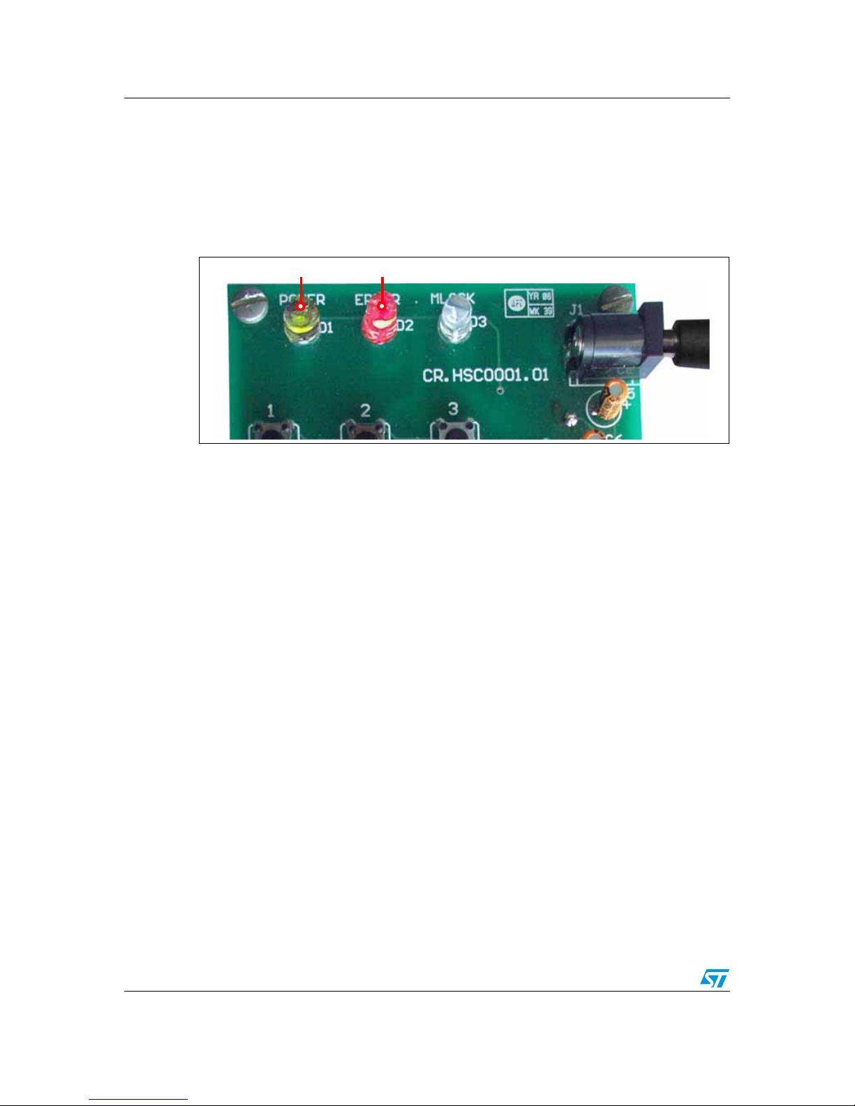
2.1.6 Error conditions in user mode
There are various error states for this system, as explained below. For each of the errors
encountered the red error LED glows (see Figure 12) for approximately 4-5 seconds.
ON
ON
Page 12
Running the security door application UM0408
12/27
1. Wrong 5-digit user code
The user enters a 5-digit user code which does not match any of the valid user codes
already added in the system. This event is logged in the EEPROM and can be seen
through the GUI.
2. Time-out condition between 2 key presses
The gap between two key press events exceeds 5 seconds.
Figure 12. Error condition
2.1.7 User-code tampering
When the user consecutively enters three wrong 5-digit user codes within 10 minutes, the
system enters a user-code tampering state. This condition is presented by the red error LED
(see Figure 12) glowing for approximately 10 minutes. During this time, the magnetic lock is
disabled. This event is logged in the EEPROM.
This condition can be exited in one of two-ways, either by waiting for 10 minutes or by
entering the administrator password to return the system back to a normal state (which
returns the LEDs back to just green Power). This event is also, logged in the EEPROM.
All the logged events can be seen in the GUI.
Note: While the system is in the user-code tampering state, no other commands (except the
entering of the administrator password) are acknowledged by the system either through the
keys or through the GUI.
2.2 Administrator mode through board
2.2.1 Add new user code
To add a new user code to the system, follow the steps below:
ON
ON
Page 13

UM0408 Running the security door application
13/27
1. Press the * key.
The red Error LED starts flashing, indicating that you are in administrator mode.
2. Enter the admin password within 1 minute.
– If the admin password is valid, the red error LED flashes 6-times.
– If the admin password is wrong, the red error LED glows for approximately 12
seconds. After this the system exits admin mode. Also, this event is logged in the
EEPROM as "Invalid Password: Error" and can be seen through the GUI.
– If the admin password is not entered within 1 minute, the red error LED glows for
approximately 12 seconds. After this the system exits admin mode.
3. Press the
*
key, within 1 minute
–If
*
is pressed, the system checks if there is space to accommodate a new user. If
yes, the red error LED flashes 6-times. Otherwise, no additional users can be
added and the red error LED flashes 30-times and the system exits admin mode.
– If any other key is pressed, the red error LED glows for approximately 12 seconds.
After this the system exits admin mode.
– If no key is pressed within 1 minute, the red error LED glows for approximately 12
seconds. After this the system exits admin mode.
4. Enter the new user code to be added, within 1 minute.
– If a 5-digit user code is entered, the system checks if it exists. If not found, the red
error LED flashes 6-times. If it exists, the red error LED glows for approximately 12
seconds and the system exits admin mode.
– If user code is not entered within 1 minute, the red error LED glows for
approximately 12 seconds. After this the system exits admin mode.
5. Press the
*
key, within 1 minute
–If
*
is pressed, this is confirmation by the user to add the user code. The system is
updated and the red error LED flashes 18-times. After this the system exits admin
mode.
– If any other key is pressed, the red error LED glows for approximately 12 seconds.
After this the system exits admin mode. No new user code is added to the system.
– If no key is pressed within 1 minute, the red error LED glows for approximately 12
seconds. After this the system exits admin mode. No new user code is added to
the system.
The adding new user event is logged in the EEPROM and can be seen through the
GUI.
Note: You are not allowed by the system to add "00000" or admin password as user code. Any
attempt is handled as ‘user code already exists’ and the red error LED glows for
approximately 12 seconds and the system exits admin mode.
2.2.2 Delete user code
To delete a user code from the system, follow the steps shown below:
Page 14

Running the security door application UM0408
14/27
1. Press the * key.
The red error LED starts flashing, indicating that you are in administrator mode.
2. Enter the admin password, within 1 minute.
– If the admin password is valid, the red error LED flashes 6-times.
– If the admin password is wrong, the red error LED glows for approximately 12
seconds. After this the system exits admin mode. Also, this event is logged in the
EEPROM as "Invalid Password: Error" and can be seen through the GUI.
– If the admin password is not entered within 1 minute, the red error LED glows for
approximately 12 seconds. After this the system exits admin mode.
3. Press the
# key, within 1 minute
–If
# is pressed, the system checks if there is any user code in the system to be
deleted. If yes, the red error LED flashes 6 times. Otherwise, (no user code to
delete) the red error LED flashes 30 times and the system exits admin mode.
– If an incorrect key is pressed, the red error LED glows for approximately 12
seconds. After this the system exits admin mode.
– If no key is pressed within 1 minute, the red error LED glows for approximately 12
seconds. After this the system exits admin mode.
4. Enter the user code to be deleted, within 1 minute.
– If a 5-digit user code is entered, the system checks if it exists. If it exists, the red
error LED flashes 6 times. If not found, the red error LED glows for approximately
12 seconds and the system exits admin mode.
– If a user code is not entered within 1 minute, the red error LED glows for
approximately 12 seconds. After this the system exits admin mode.
5. Press the
*
key, within 1 minute
–If
*
is pressed, this is confirmation by the user to delete the user code. The
system is updated and the red error LED flashes 18 times. After this the system
exits admin mode.
– If an incorrect key is pressed, the red error LED glows for approximately 12
seconds. After this the system exits admin mode. No user code is deleted from the
system.
– If no key is pressed within 1 minute, the red error LED glows for approximately 12
seconds. After this the system exits admin mode. No user code is deleted from the
system.
Deleting a user event is logged in the EEPROM and can be seen through the GUI.
Note: The system prevents the admin password from being deleted. Any attempt to do so is
handled as ‘user code not found’ and the red error LED glows for approximately 12 seconds
and the system exits admin mode.
2.3 Administrator password reset through board
In the event that the administrator password is forgotten, it can be reset to the default value
of "00000". This is done as follows:
Page 15

UM0408 Running the security door application
15/27
1. Press the # key.
The red error LED starts to flash, indicating that you are in administrator reset
password mode.
2. Enter "12345", within 1 minute.
– If correctly entered, the red error LED flashes 6 times.
– If incorrectly entered, the red error LED glows for approximately 12 seconds. After
this the system exits admin reset password mode.
– If nothing entered within the 1 minute, the red error LED glows for approximately
12 seconds. After this the system exits from admin reset password mode.
3. Press the
# key, within 1 minute.
–If
# is pressed, the red error LED flashes 18 times.
– If an incorrect key is pressed, the red error LED glows for approximately 12
seconds. After this the system exits from admin reset password mode.
– If no key is pressed within 1 minute, the red error LED glows for approximately 12
seconds. After this the system exits from admin reset password mode.
4. Press the
# key.
The red error LED flashes 6 times.
5. Enter "54321", within 1 minute.
– If a correct entry is made, the red error LED flashes 6 times.
– If an incorrect entry, the red error LED glows for approximately 12 seconds. After
this the system exits from admin reset password mode.
– If nothing is entered within 1 minute, the red error LED glows for approximately 12
seconds. After this the system exits from admin reset password mode.
6. Press the
# key, within 1 minute.
–If
# is pressed, this is confirmation for the administration password reset to
"00000". The red error LED flashes 18 times. The system exists from the admin
reset password mode.
– If an incorrect key is pressed, the red error LED glows for approximately 12
seconds. The administrator password is not reset and the system exits from admin
reset password mode.
– If no key is pressed within 1 minute, the red error LED glows for approximately 12
seconds. The administrator password is not reset and the system exits from admin
reset password mode.
2.4 Administrator mode through PC graphical user interface
2.4.1 Connecting to the PC
Connect the RS232 serial cable between the demonstration board and the PC and power on
the board.
Note: Even if the board is connected with the RS232 serial cable with power on, the system enters
the GUI mode as soon as the administrator password is entered in the login window. You
need to make sure that the system is not in the process of executing another command at
this time, otherwise unexpected behavior is possible.
Page 16
Running the security door application UM0408
16/27
2.4.2 Powering on the board
This is the same process as with the user mode. Refer to Section 2.1.1 on page 10.
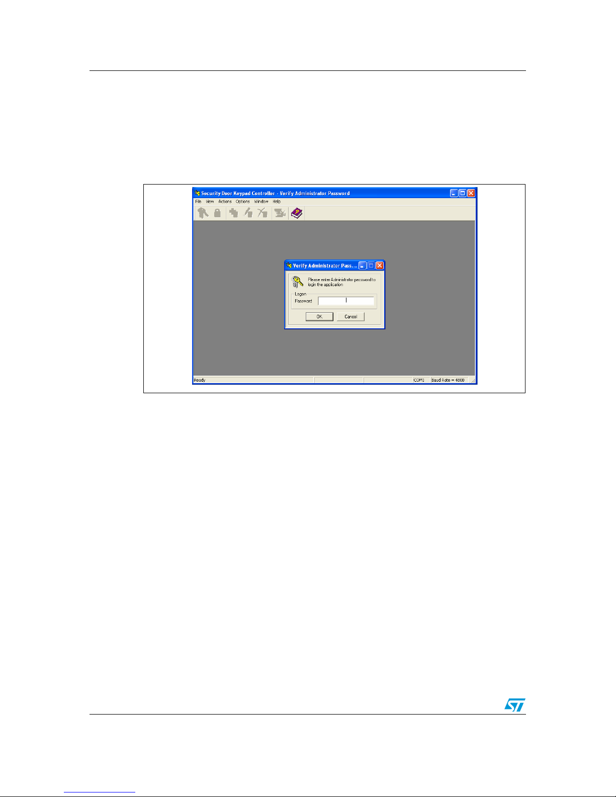
2.4.3 The first GUI window - login GUI mode
Opening the GUI executable, the first window appears as shown in Figure 13.
Figure 13. First GUI window
Enter the administrator password. If correct, administrator mode is entered and all features
are available. Otherwise, an invalid password error message appears.
For details on each feature and its usage refer to the GUI help manual.
Note: When in GUI mode, the system cannot be used or configured in user or administrator
modes configuration from the board itself.
2.4.4 Communication setting
Ensure that the communication settings between the board and GUI are as follows:
● baud rate is set to 4800
● right COM port is selected
Follow the steps below to configure the communication settings through the GUI (see
Figure 14),
1. Go to Options, Connection Settings…
2. Choose the serial communication port to which board is connected
3. Choose the baud rate = 4800
4. Click OK
Note: The chosen settings are automatically saved for future sessions.
Page 17
UM0408 Running the security door application
17/27
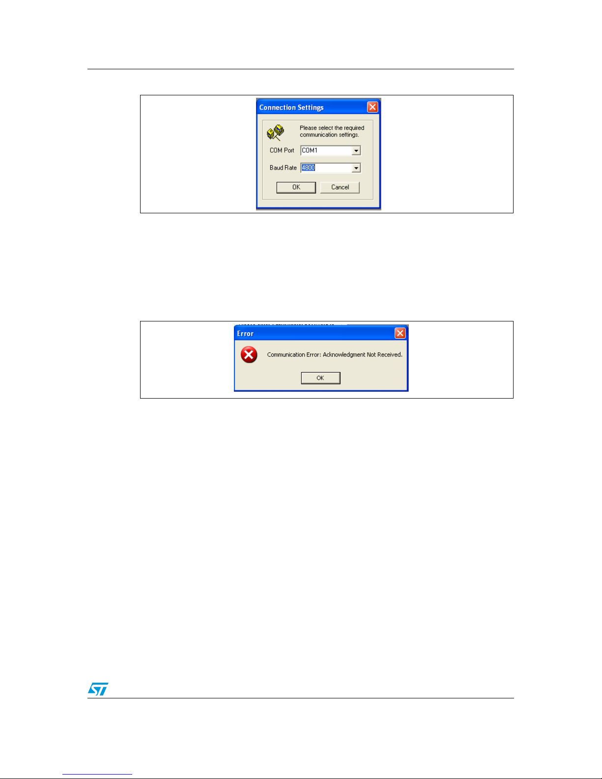
Figure 14. Communication settings window
2.4.5 Communication error
If the following message appears (Figure 15), then it could be due to the following reasons:
1. Baud rate mismatch (set it to 4800), the red error LED glows
2. RS232 serial cable not connected properly
3. Incorrect COM port selection
Figure 15. Communication error message
Page 18

Running the security door application UM0408
18/27
2.4.6 Features supported by the GUI
Following features are supported by the GUI,
1. Add user code (Actions)
Add new user code to the system.
2. Delete user code
Delete an existing user code from the system.
3. Delete all user codes
Delete all existing user codes from the system. This feature is supported only through
GUI.
4. Modify user code
Replace the existing user code with a new one. This feature is supported only through
GUI.
5. View event log
Summary of all the events logged in EEPROM of the system. This feature is supported
only through GUI.
6. Delete event log
Delete the EEPROM data. This feature is supported only through GUI.
7. View code list
View all the active user code for the system. This feature is supported only through
GUI.
8. Change admin password
Change the admin password. This feature is supported only through GUI.
To select these features you can use either the tool bar (as shown in Figure 16) or the menu
bar (see Figure 17).
Figure 16. Tool bar
Figure 17. Menu bar
For details on each feature and its usage refer to the GUI help manual.
Page 19

UM0408 Running the security door application
19/27
2.4.7 Logoff GUI mode
After working in administrator mode through the PC GUI, you can choose to log-off (File,
Logoff). This sends a disconnect command to the board (see Figure 18). Then close the
GUI window. Remove the RS232 serial cable.
Shortcut: By directly closing the GUI window, a disconnect command is directly issued
to the board. Remove the RS232 serial cable.
All three LEDs glow for 4-5 seconds (see Figure 9).
Figure 18. Logoff message
The system then becomes available to operate in user or administrator modes through the
board itself (see Figure 10).
2.4.8 Automatic Logoff from GUI mode (through watchdog)
The system is designed in such a way to support automatic log-off from GUI mode, if no
communication from PC is received.
No communication from the PC could be due to:
● RS232 cable un-plugged without proper log-off from the GUI
● GUI idle for long time, no serial communication between PC and board
In this situation the system watchdog is activated for approximately 30 seconds. After that
the system resets, all the three LEDs start glowing for 4-5 seconds (see Figure 9). The
system then becomes available to operate in user or administrator modes through the board
itself (see Figure 10).
Note: As this is a case of improper log-off, it is desirable that when the serial communication is re-
established between the PC and board the user should re-login to view the real status.
Otherwise the status on the GUI may not be updated.
Page 20

Abbreviations UM0408
20/27
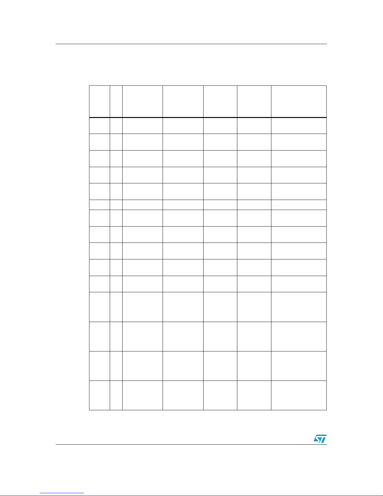
Appendix A Abbreviations
Table 1. Abbreviations
No. Acronym Definition
1 RTC Real Time Clock
2 PC Personal Computer
3 EEPROM Electrically Erasable Programmable Read Only Memory
4 SPI Serial Peripheral Interface
5 LED Light Emitting Diode
6 SCI Serial Communication Interface
7 OS Operating System
8 ICC In-circuit communication
9Admin Administrator
Page 21

UM0408 Demonstration board schematic
21/27
Appendix B Demonstration board schematic
1
2
3
4
56
A
B
C
D
6
5
4
3
2
1
D
C
B
A
Scale Sheet
Size FCSM No. DWG No. Rev
1of1
B 08-AUG-2006 0.1
*
RDI
1
2
3
4
5
6
7
8
9
10
CON1
ICC
RESET
VCC
R9
10k
ICCDATA
ICCCLK
ICC CON
MCU
C4
100nF
1
6
2
7
3
8
4
9
5
J2
DB9/F
3.3V
RS232 INTERFACE
RDI
TDO
KEYPAD 3X4
1
2
3
J1
JACK
C1
100nF
VCC
4.3V~20V
3.3V VCC
GND
C1+
1
V+
2
C1-
3
C2+
4
C2-
5
V-
6
T2OUT
7
R2IN
8
R2OUT
9
T2IN
10
T1IN
11
R1OUT
12
R1IN
13
T1OUT
14
GND
15
VCC
16
U5
ST3232CDR
VSS
1
VDD
2
RESET#
3
PB4
8
OSC1
20
OSC2
19
PA0
18
PB5
9
RDI/PB6
10
PA4
14
PA5/ICCDATA
13
PA6/ICCLCK
12
PA7/TDO
11
PA1
17
SS#/PB0
4
SCK/PB1
5
MISO/PB2
6
MOSI/PB3
7
PA2
16
PA3
15
U4
ST7FLITE39F2M6
S#
1
Q
2
W
3
VSS
4
VCC
8
HOLD
7
C
6
D
5
U3
M95080-WMNP
RST#
1
MR
2
SAL#
3
VSS
4
TP4
8
TP3
7
TP2
6
TP1
5
VOUT
12
VBAT
11
PF0#
10
VREF
9
BLD#
16
PF1
15
VCCSW#
14
VCC
13
U2
STM1403ASNQ6F
5
6
8
7
9
4
#
0
1
2
3
R6
10k
PB5
PA4
PA1
PA3
PA0
VCC
RESET
ICCDATA
ICCCLK
I
1
G
2
O
3
U1
KF33BDT-TR
D1
POWER
R1
330
VCC
R4
10k
SCK
MOSI
SS
MISO
R11
10k
VCC
SS
SCK
MISO
MOSI
ERROR
PB5
PA0
PA1
MLOCK
PA3
PA4
TDO
R14
330
D3
MLOCK
R13
330
D2
ERROR
C3
100nF
VCC
R5
10k
VCC
1
2
JP1
NH
1
2
JP2
NL
1
2
JP3
NH
1
2
JP4
NL
R12
10M
R8
10M
R10
10M
R7
10M
Vout
D4
BAT54JFILM
BT1
3V
BZ1
BUZZER
R2
10k
R3
10k
Vout
VCC
C2
100nF
EEPROM
POWER SUPPLY
TAMPER DETECTI ON
KEYPAD CONTROLLER
C7
100nF
C8
100nF
C9
100nF
C10
100nF
VCC=3.3V (150~200mA)
C11
10nF
VCC
VCC
C5
2.2uF/10V
C6
1uF/10V
ICCDATA
ICCCLK
Vout
Vout
Page 22
Bill of materials UM0408
22/27
Appendix C Bill of materials
Table 2. Bill of materials
Designator
Quantity
Reference
Value /
Generic Part
Number
Package
Manufact/
Supplier
Manufacturer's
/Supplier's ordering
code / Orderable
Part Number
U4 1
ST7FLite39F2
M6 - MCU
ST7FLite39F2
M6
SO-20 ST ST7FLite39F2M6
U3 1 EEPROM
M95080WMN6
SO-8 ST M95080-WMN6
U2 1 Tamper Detect
STM1403ASN
Q6F
QFN-16 ST STM1403ASNQ6F
U1 1
Voltage
Regulator
KF33BDT-TR DPAK-3 ST KF33BDT-TR
U5 1
RS-232
interface
ST3232 SO-16 ST ST3232CDR
D4 1 Diode BAT54J SOD-323 ST BAT54JFILM
J2 1
RS-232
connector
DB9/F Farnell 105-6112
CON1 1 ICC Connector
Header 5x2/
IDC-10B
Farnell 1106782
D1 1 LED Green
Throughhole
Farnell 884-698
D2 1 LED Red
Throughhole
Farnell 942-492
D3 1 LED Yellow
Throughhole
Farnell 942-455
01
Push-button
Switches
4-leg
Throughhole (Push-
4)
Farnell 535-916
11
Push-button
Switches
4-leg
Throughhole (Push-
4)
Farnell 535-916
21
Push-button
Switches
4-leg
Throughhole (Push-
4)
Farnell 535-916
31
Push-button
Switches
4-leg
Throughhole (Push-
4)
Farnell 535-916
Page 23

UM0408 Bill of materials
23/27
41
Push-button
Switches
4-leg
Throughhole (Push-
4)
Farnell 535-916
51
Push-button
Switches
4-leg
Throughhole (Push-
4)
Farnell 535-916
61
Push-button
Switches
4-leg
Throughhole (Push-
4)
Farnell 535-916
71
Push-button
Switches
4-leg
Throughhole (Push-
4)
Farnell 535-916
81
Push-button
Switches
4-leg
Throughhole (Push-
4)
Farnell 535-916
91
Push-button
Switches
4-leg
Throughhole (Push-
4)
Farnell 535-916
*
1
Push-button
Switches
4-leg
Throughhole (Push-
4)
Farnell 535-916
#
1
Push-button
Switches
4-leg
Throughhole (Push-
4)
Farnell 535-916
BZ1 1 DC-Buzzer
Throughhole (85db,
1.5V-27V
DC)
Stuff S.E. - B-20-B
1 3V Battery CR2032 Coin type MAXEL MAXELCR2032
BT1 1 Battery Socket BATT-C MAXEL MAXELCR2032
R11,
R2,
R3,
R4,
R5,
R6, R9
7
Resistor
10K 0805 Local
Table 2. Bill of materials
Designator
Quantity
Reference
Value /
Generic Part
Number
Package
Manufact/
Supplier
Manufacturer's
/Supplier's ordering
code / Orderable
Part Number
Page 24

Bill of materials UM0408
24/27
R1,
R13,
R14
3 Resistor 330 0805 Local
R10,
R12,
R7,R8
4 Resistor 10M 0805 Local
C1,
C10,
C2,C3,
C4,
C7,C8,
C9
8 Capacitor 0.1 F 0805 Local
C6 1 Capacitor 1 F/10V CAP Local
C5 1 Capacitor 2.2 F/10V CAP Local
J1 1
Power Jack (for
adaptor)
power jack
for adaptor
Local
JP1,
JP2,
JP3,
JP4
4 Jumper
SIP-2 (berg
strip)
Local
C11 1 Capacitor 10nF 0805 Local
Table 2. Bill of materials
Designator
Quantity
Reference
Value /
Generic Part
Number
Package
Manufact/
Supplier
Manufacturer's
/Supplier's ordering
code / Orderable
Part Number
Page 25

UM0408 Troubleshooting
25/27
Appendix D Troubleshooting
D.1 Communication error
A "Communication error" message may appear on the PC screen (as in Figure 15) for any of
the following reasons:
1. Baud rate mismatch (set it to 4800), signaled by the red error LED glowing
2. RS232 serial cable not connected or not connected properly
3. Incorrect COM port selection (set it to correct setting based on the PC configuration)
4. Board not power-on
In all the above cases, the user needs to re-start the GUI.
5. Red error LED glowing
For this case, when the Error LED (red) turns off, then the user needs to re-start the
GUI.
D.2 Time-out error
The "Time-out error" (see Figure 19), is shown when the command issued by the user takes
longer to finish than expected by the system on the GUI side, though the operation is
completed on the board side. In this case, the user needs to re-start the GUI to get the real
system status.
Figure 19. Time-out error
D.3 Delete all users
Deleting all users is a time-consuming process. To ensure that this is completed, after
receiving the OK prompt from the GUI (see Figure 20), make sure that the "Code in system
= 0" in the status bar. Wait a little longer if this has not been updated. As soon as the status
bar displays "Code in system = 0" the system is ready for next command (see Figure 21).
Note: If any command is sent and the delete all users operation is not complete, system behavior
is not guaranteed.
Figure 20. Delete all users - OK window
Figure 21. Delete all users - Status bar
Page 26

Revision history UM0408
26/27
3 Revision history
Table 3. Document revision history
Date Revision Changes
06-Apr-2007 1 Initial release.
Page 27

UM0408
27/27
Please Read Carefully:
Information in this document is provided solely in connection with ST products. STMicroelectronics NV and its subsidiaries (“ST”) reserve the
right to make changes, corrections, modifications or improvements, to this document, and the products and services described herein at any
time, without notice.
All ST products are sold pursuant to ST’s terms and conditions of sale.
Purchasers are solely responsible for the choice, selection and use of the ST products and services described herein, and ST assumes no
liability whatsoever relating to the choice, selection or use of the ST products and services described herein.
No license, express or implied, by estoppel or otherwise, to any intellectual property rights is granted under this document. If any part of this
document refers to any third party products or services it shall not be deemed a license grant by ST for the use of such third party products
or services, or any intellectual property contained therein or considered as a warranty covering the use in any manner whatsoever of such
third party products or services or any intellectual property contained therein.
UNLESS OTHERWISE SET FORTH IN ST’S TERMS AND CONDITIONS OF SALE ST DISCLAIMS ANY EXPRESS OR IMPLIED
WARRANTY WITH RESPECT TO THE USE AND/OR SALE OF ST PRODUCTS INCLUDING WITHOUT LIMITATION IMPLIED
WARRANTIES OF MERCHANTABILITY, FITNESS FOR A PARTICULAR PURPOSE (AND THEIR EQUIVALENTS UNDER THE LAWS
OF ANY JURISDICTION), OR INFRINGEMENT OF ANY PATENT, COPYRIGHT OR OTHER INTELLECTUAL PROPERTY RIGHT.
UNLESS EXPRESSLY APPROVED IN WRITING BY AN AUTHORIZED ST REPRESENTATIVE, ST PRODUCTS ARE NOT
RECOMMENDED, AUTHORIZED OR WARRANTED FOR USE IN MILITARY, AIR CRAFT, SPACE, LIFE SAVING, OR LIFE SUSTAINING
APPLICATIONS, NOR IN PRODUCTS OR SYSTEMS WHERE FAILURE OR MALFUNCTION MAY RESULT IN PERSONAL INJURY,
DEATH, OR SEVERE PROPERTY OR ENVIRONMENTAL DAMAGE. ST PRODUCTS WHICH ARE NOT SPECIFIED AS "AUTOMOTIVE
GRADE" MAY ONLY BE USED IN AUTOMOTIVE APPLICATIONS AT USER’S OWN RISK.
Resale of ST products with provisions different from the statements and/or technical features set forth in this document shall immediately void
any warranty granted by ST for the ST product or service described herein and shall not create or extend in any manner whatsoever, any
liability of ST.
ST and the ST logo are trademarks or registered trademarks of ST in various countries.
Information in this document supersedes and replaces all information previously supplied.
The ST logo is a registered trademark of STMicroelectronics. All other names are the property of their respective owners.
© 2007 STMicroelectronics - All rights reserved
STMicroelectronics group of companies
Australia - Belgium - Brazil - Canada - China - Czech Republic - Finland - France - Germany - Hong Kong - India - Israel - Italy - Japan -
Malaysia - Malta - Morocco - Singapore - Spain - Sweden - Switzerland - United Kingdom - United States of America
www.st.com
 Loading...