

Page 1
UM0151
User Manual
STVP programming toolkit
Introduction
The STVP programming toolkit provides a set of C++ source and header files that can be
used to design a customized programming application for any ST programming hardware
that is supported by STVP.
The provided files contain the source code for functions that allow your programmin g
application to access STVP’s low level DLLs.
With access to these STVP DLLs, you can program ST7, STM8 and STM32
microcontrollers using any supported programming hardware (ST7-STICK, ST socket
boards, EPB, DVP3, EMU3, STice, ST-LINK, ST-TSLINK and Raisonance STX-RLINK) and
programming methods (socket, in-circuit or in-situ programming).
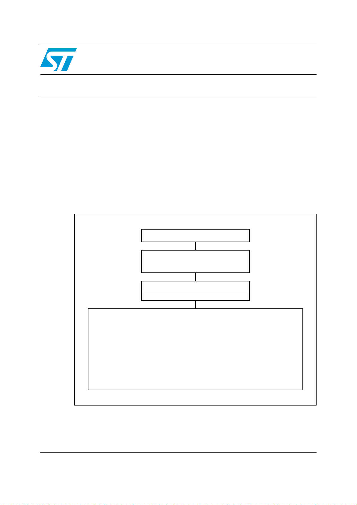
Figure 1.
Programming application schematic
Your programming application
Programming toolkit
- PtkApi.ccp
- PtkToolBox.ccp
Programming DLLs (from STVP)
Configuration files (from STVP)
1. ST7 Flash STICK: In-circuit progra mmi n g (ICP )
2. DVP3 series emulator: In-circuit programming (ICP)
3. EMU3 series emulator with ICC Add-on (ICP)
4. ST7SB socket board: Programming sockets for all ICP capable hardware
5. EPB series programmer:
- Programming sockets
- ICP depending on version and target ST microcontroller
6. STice advanced emulation system (ICP)
7. ST-LINK in-circuit debugger/programmer (ICP)
8. STX-RLink in-circuit debugger/programmer (ICP)
9. ST-TSLINK programming dongle (ICP)
Note: Creating a programming application with the STVP programming toolkit requires the
installation of ST Visual Programmer version 1.9.1 or later.
June 2011 Doc ID 11472 Rev 5 1/29
www.st.com
Page 2

Contents UM0151
Contents
1 Overview . . . . . . . . . . . . . . . . . . . . . . . . . . . . . . . . . . . . . . . . . . . . . . . . . . 3
1.1 About the user manuals . . . . . . . . . . . . . . . . . . . . . . . . . . . . . . . . . . . . . . . 3
1.2 Getting assistance . . . . . . . . . . . . . . . . . . . . . . . . . . . . . . . . . . . . . . . . . . . 3
2 Programming toolkit contents . . . . . . . . . . . . . . . . . . . . . . . . . . . . . . . . . 4
3 Understanding the STVP DLLs . . . . . . . . . . . . . . . . . . . . . . . . . . . . . . . . 6
4 Designing a custom programming application . . . . . . . . . . . . . . . . . . . 7
4.1 Setting up the DLL environment . . . . . . . . . . . . . . . . . . . . . . . . . . . . . . . . . 7
4.2 Configuring the device and the programming hardware . . . . . . . . . . . . . . . 8
4.3 Accessing the memory image . . . . . . . . . . . . . . . . . . . . . . . . . . . . . . . . . . 9
4.3.1 Loading a file . . . . . . . . . . . . . . . . . . . . . . . . . . . . . . . . . . . . . . . . . . . . . . 9
4.3.2 Writing in the memory image . . . . . . . . . . . . . . . . . . . . . . . . . . . . . . . . . 10
4.4 Connecting to the device . . . . . . . . . . . . . . . . . . . . . . . . . . . . . . . . . . . . . 10
4.4.1 Blank checking the device . . . . . . . . . . . . . . . . . . . . . . . . . . . . . . . . . . . 10
4.4.2 Programming the device . . . . . . . . . . . . . . . . . . . . . . . . . . . . . . . . . . . . 11
4.4.3 Verifying the programming of the device . . . . . . . . . . . . . . . . . . . . . . . . 11
4.4.4 Reading the device . . . . . . . . . . . . . . . . . . . . . . . . . . . . . . . . . . . . . . . . 11
5 DLL supported functions . . . . . . . . . . . . . . . . . . . . . . . . . . . . . . . . . . . . 12
5.1 DLL environment functions . . . . . . . . . . . . . . . . . . . . . . . . . . . . . . . . . . . . 12
5.2 Hardware and device configuration functions . . . . . . . . . . . . . . . . . . . . . . 16
5.3 Image area access functions . . . . . . . . . . . . . . . . . . . . . . . . . . . . . . . . . . 17
5.4 Device connection functions . . . . . . . . . . . . . . . . . . . . . . . . . . . . . . . . . . . 19
6 Programming toolkit helper functions . . . . . . . . . . . . . . . . . . . . . . . . . 22
Appendix A Product support. . . . . . . . . . . . . . . . . . . . . . . . . . . . . . . . . . . . . . . . . 27
7 Revision history . . . . . . . . . . . . . . . . . . . . . . . . . . . . . . . . . . . . . . . . . . . 28
2/29 Doc ID 11472 Rev 5
Page 3

UM0151 Overview
1 Overview
1.1 About the user manuals
This manual provides information and examples to help you develop your programming
application with the programming toolkit. It describes:
● The functions supported by the STVP DLLs
● Using the functions provided by the programming toolkit
For information about STVP and supported ST programming hardware, you can refer to the
following:
● ST Visual Programmer on-line help, information about STVP and supported hardware
and programming methods
● ST Visual Programmer Release Notes, co mplete r elease information about the current
release of STVP, including supported programming hardware and ST microcontrollers
For information about setup and connection information for supported programming
hardware, you can refer to the following:
● ST7-STICK User Manual
● ST7SB Socket Board User Manual
● ST7-EPB User Manual
● ST7-D VP3 Emulator User Manual
● ST7-EMU3 Emulator User Manual
●
STice User Manual
●
ST-LINK User Manual
●
ST-TSLINK User Manual
● Raisonance STX-RLINK User Manual (on the Raisonance web site)
For progr amming information that is specific to your ST microcontroller, refer to the relevant
datasheet.
1.2 Getting assistance
For more information, application notes, FAQs and software updates on all the ST
microcontroller families, check out the CD-ROM or our website: www.st.com
For assistance on all ST microcontroller subjec ts, or f or help using y our emulator , r efer to the
contact list provided in the Chapter Appendix A: Product support. We’ll be glad to help you.
Doc ID 11472 Rev 5 3/29
Page 4

Programming toolkit contents UM0151
2 Programming toolkit contents
The programming toolkit is a set of C++ source and header files that you integrate into your
application in order to use the programming functions supported by STVP’s DLLs. In
addition, the toolkit contains two samples that demonstrate the types of applications that
can be created.
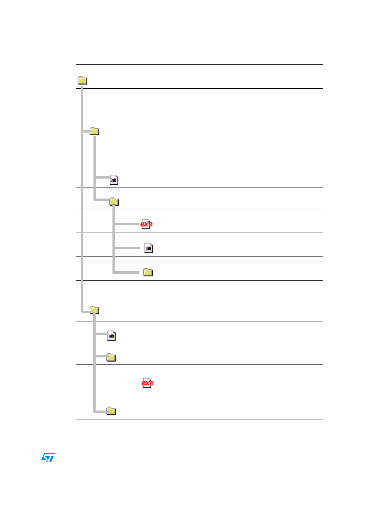
When you run the auto ex tracting zip, the programming toolkit files and this documentation
are placed in the directory that you specified on your PC. These files and folders include:
Table 1. Installed components: programmin g toolkit source and header files
Contains the C++ source files that you include in your application in order to
src:
access the functions of the STVP DLLs.
PtkApi.cpp:
Source and header that enable the importation of functions from the
application programming interfaces (API) of the STVP DLLs.
PtkApi.h:
Source and header for “Helper Functions” for tasks such as retrieving
PtkToolBox.cpp
PtkToolBox.cpp
configuration files or accessing the “memory image.” The Helper
Functions should always be used to access the configuration
information as the format and content of these databases may
change without notification when STVP is upgraded. Even if the
format of the database changes, the prototypes for the Helper
Functions will remain the same.
Note: The source files provided in the programming toolkit are in C++ format (.cpp), however they
can be compiled as C source files. Developing your application using another programming
language does not necessarily pose a compatibility problem with the STVP DLLs, however
these developers will have to rewrite the application programming interface (PtkApi.cpp).
Programming applications created using the programming toolkit rely on STVP’s DLLs and
configuration files (see the cover page). The programming toolkit does not contain thes e
files; they are installed with STVP. These files must then be placed in the same directory as
your programming ap plication. More information about these DLLs is prov ided in the next
chapter, Understanding the STVP DLLs.
Note: Both the STVP programming toolkit and the latest version of ST Visual Programmer can
be downloaded for free from www.st.com/mcu.
4/29 Doc ID 11472 Rev 5
Page 5
UM0151 Programming toolkit contents
Table 2. Source files and executables for two sample applications:
The samples, APISample.exe and MFCSample.exe , are C applications de veloped
Sample:
ApiSample:
with Visual C++ 6.0. They should be executed from the directory where you have
installed STVP version 1.9.1 or later.
Contains the C++ source and header files for a console application
that is intended to illustrate:
• How to set the hardware and MCU configuration: ST-LINK, USB,
STM8L15xC6, SWIM protocol
• How to load binary files in "PROGRAM MEMORY" and in "OPTION
BYTE" areas
• How to program and verify the "PROGRAM MEMORY"
• How to program and verify the "OPTION BYTE"
This sample can easily be rebuilt in an environment other than
Visual C++ 6.0.
Readme.txt
Distrib:
MFCSample:
Readme.txt:
Distrib:
Provides details about the use of the ApiSample application.
This subdirectory contains the executable and .hex files for the
ApiSample. The files include:
The executable for the application programming
ApiSample.exe:
interface. This ex ecutable should be ex ecuted from
the directory where you have installed STVP.
Dummy application code that the sample
option.hex:
application programs to the option byte area of the
ST microcontroller’s memory.
Dummy application code that the sample
progmem.hex:
application programs to the ST microcontroller’s
Program Memory area.
Contains the C++ source and header files for an application that
uses the Microsoft Foundation Classes. In addition to the features
demonstrated in ApiSample, MFCSample specifically illustrates the
use of the helper functions to access and configure data.
Provides details about the use of the MFCSample application.
This subdirectory contains the MFCSample executable file.
res:
MFCSample.ex
e:
The executable for the application programming
interface. This ex ecutable should be ex ecuted from
the directory where you have installed STVP.
Contains the resource files for the graphical interface, which were
used to build the sample application.
Doc ID 11472 Rev 5 5/29
Page 6

Understanding the STVP DLLs UM0151
3 Understanding the STVP DLLs
Because your programming application must use the STVP DLLs, you should first
understand their roles. The software elements that your application accesses and their
relationships are shown in Figure 2. These elements include:
Table 3. STVP DLLs and configuration files
Configuration files
DBCFILE.CNF Contain a database of information on all STVP supported devices (memory mappings, option
TOOLS.CNF
DLLs
DBCA60.DLL
bytes, protocols) and programming hardware configurations (supported devices, protocols,
communication ports). Typically, these files evolve with new releases of STVP. However, if you
use the programming toolkit, these evolutions should not pose a problem for your application.
Database configuration access. Used by HAPL, EPRCORE60 and programming toolkit to
get lists of devices, programming hardware and other hardware and de vice information from the
configuration files.
EPRCORE60.DLL
FILE60.DLL
HAPL.DLL
LEF60.DLL
Epromer core. Keeps track of the device description and creates the programming interface
between the GUI and the appropriate HAPL.
A component DLL of the EPRCORE60 layer . It ensures loading and sa ving of the de vice binary
files. Supported formats include Motorola (.S19) and Intel (.HEX).
Hardware programming level. Hardware specific DLLs that are in charge of programming a
specific type of device using a specific type of hardware. The EPRCORE60 loads the
appropriate HAPL for the hardware and device configuration.
Logging / Error features . Ensures the propagation of errors between the different layers. It
may also log execution traces.
Figure 2. STVP DLLs and configuration files
6/29 Doc ID 11472 Rev 5
Page 7

UM0151 Designing a custom programming application
4 Designing a custom programming application
For the purposes of understand ing th e di f ferent functions suppo rted by the STVP DLL s, the
programming process can be divided into four categories of functions:
● Setting up the DLL environment
● Configuring the device and the programming hardware
● Accessing the memory image
● Connecting to the device
The following sections provide coded examples to show how an application might use the
different functions in each category to accomplish specific programming tasks.
Before getting started, it is also important to recognize that your application can be
dynamic, offering as much control of hardware configuration and options as STVP, or
static, with the hardware configuration hard-coded into the programming application. The
programming toolkit provides Helper Functions that allow you to return lists of devices,
hardware and protocols at run time so that they can be used by your application (refer to
Programming toolkit helper functions). Howev er, for simplicity, the examples provided in the
following section are for a static interface with the configuration hard-coded into the
application.
4.1 Setting up the DLL environment
The STVP DLLs described in Section 3 must be initialized by your application and the
callback functions that allow it to manage errors, messages and process execution must
also be initialized.
The following is a standar d initialization that you might use in your application.
long CALLBACK AppendMessageText( const char* szMsg)
{
.....
}
long CALLBACK AppendErrorText( const char* szMsg)
{
.....
}
long CALLBACK AppendWarningText( const char* szMsg)
{
.....
}
long CALLBACK UpdateProgress( int percentage* szMsg)
{
.....
}
Note: The CALLBACK notation used here is standard when using Microsoft Visual Studio C++.
However, for other development environments, you may have to use a different notation.
InitDLLCallBack()
{
Doc ID 11472 Rev 5 7/29
Page 8

Designing a custom programming application UM0151
LSetErrorCallBack( AppendErrorText);
LSetWarningCallBack( AppendWarningText);
LSetMessageCallBack( AppendMessageText);
LSetProgressCallBack( UpdateProgress);
}
main() {
// Load DLLs and Initialize the address of API
// functions
if (LoadDlls(“C:\my_installation\STVP\”)==1) {
InitDLLCallBack();
.....
// Log everything
LOpenLog( “Activity.log”);
.....
SetProgrammingConfiguration();
DoesProgrammingJob();
.....
LCloseLog();
Clean();
}
}
4.2 Configuring the device and the programming hardware
The STVP DLLs support numerous hardware configurations and target devices. Correct
identification of the programming hardware is important in establishing the necessary
hardware connections, as well as programming and verification of the target device. Once
the configuration is set, the correct HAPL.DLL is load ed to m anage communication with the
device.
Based on the device selected for programming, the programming software also creates
buffer area in your PCs RAM for the data that will be programmed to the device. This buffer
is called the Memory Image. It is also used as a model to check against when verifying the
programming of the device.
The routine below is initiated by the SetProgrammingConfiguration() function. This is an
example of a static interface where the following configuration is hard-coded into the
application:
Hardware: ST-LINK
Protocol: SWIM
Device: STM8L15xC6
Port: USB
Note: This example is incomplete as some parts of the code are implementation-driven.
BOOL SetProgrammingConfiguration()
{
// Select the hardware in this case ST-LINK with
// “SWIM”
// protocol, FALSE means that we are not using
// simulation mode
if (ESelectHard(“ST-LINK”, “SWIM” ,FALSE)==0)
8/29 Doc ID 11472 Rev 5
Page 9

UM0151 Designing a custom programming application
{
return false;
}
// Prevent from opening a warning dialog box when
// Option byte protection bit is to be programmed.
// By default, the Protection warning dialog box is
// opened
if (ESetPreferences (PROTECTION_WARNING, FALSE)==0}
{
return false;
}
// Select the device : STM8L15xC6 device
if (ESelectDevice(“STM8L15xC6”)==0))
{
return false;
}
if (ESelectPort (“USB”)==0))
{
return false;
}
return true;
}
4.3 Accessing the memory image
Once the programming hardware, the device and the port have been specified, the
EPRCORE60.DLL allocates memory structures and buffer s for each memory area
supported by the device (PROGRAM, DATA, OPTION). The memory buffer internally
allocated by EPRCORE60 is called the Memory Image. A unique internal identifier is giv en
to each area. This identifier should be used later in t he API fu nctions when ever you need to
identify a specific memory area.
With the Memory Image established, the programing applicat ion can no w access th is b uf fer
and load the binary file (.HEX or .S19) that you wish to program to your device, as well as
writing any information that is specific to the programming of each device (ex. a product
serial number).
Caution: If your software reads y our ST microcontroller ’ s memory, the data from the de vice ov erwrites
any data that is already stored in the Memory Image.
4.3.1 Loading a file
In the following example the specified binary file (MyAppli.S19), which is to be programmed
to the target device, is retrieved and saved to the Memory Image. This file is located and
saved by the FILE60 component of the EPRCORE60.
// Search the PROGRAM MEMORY ID
unsigned long iAreaId
if (EGetId("PROGRAM MEMORY", &iAreaId) == 1)
{
// Load the file MyAppl.S19 in the program memory area
iReturn = ELoadFile(“MyAppl.S19”,iAreaId);
}
Doc ID 11472 Rev 5 9/29
Page 10

Designing a custom programming application UM0151
4.3.2 Writing in the memory image
You can also write punctually to specific memory locations as shown in this example. In the
sample provided the data is an integer that is incremented each time a device is
programmed. For example, this value could be a product serial number or other
identification.
.....
// Write 1,2,3,4 in memory image at location 0x2000
for (i=1;i<=4;i++)
{
SetByteInImageMemory(STM8L15xC6, "PROGRAM MEMORY",0x2000+i- 1,i);
}
.....
4.4 Connecting to the device
The following examples use the functions that interact with the device that is to be
programmed. At this stage your programming application is writing to the device’s memory,
the data which has been stored in the Memory Image. This section provides examples
specifically for blank checking, programming, verifying and reading a device.
4.4.1 Blank checking the device
Blank checking the device’s memory allows you to confirm that the device has not already
been programmed. Some devices do not support blank check. To avoid an error when not
supported, you can use the IsBlankCheckAvailable function as in illustrated in the e xample
below.
// Search the PROGRAM MEMORY ID
unsigned long iAreaId
// IsBlankCheckAvailable will prevent from executing
// the blank check, when the MCU does not support blank
// check which is the case for the current
// configuration (STM8L15xC6)
if (IsBlankCheckAvailable("STM8L15xC6","PROGRAM MEMORY")==true)
{
if (EGetId("PROGRAM MEMORY", &iAreaId) == 1)
{
// Process all the PROGRAM MEMORY
EBlankAll(iAreaId);
// Blank check between 0x2000 and 0x3000
EBlankArea( iAreaId, 0x2000L, 0x3000L);
}
}
4.4.2 Programming the device
The programming routine writes the content s of the Memory Image to the specified areas of
the device’s memory.
// Search the PROGRAM MEMORY ID
unsigned long iAreaId
if (EGetId("PROGRAM MEMORY", &iAreaId) == 1)
10/29 Doc ID 11472 Rev 5
Page 11

UM0151 Designing a custom programming application
{
// Process all the PROGRAM MEMORY
EProgAll(iAreaId);
// Program only between 0x2000 and 0x3000
EProgArea(iAreaId, 0x2000L, 0x3000L);
}
4.4.3 Verifying the programming of the device
The verification routine compares the contents of the programmed device memory with the
data as you intended to program it. This is the data stored in the Memory Image.
Caution: It is very important not to read the device’s memory prior to verification. When reading the
device, the contents of the device’s memory overwrite the contents of the Memory Image,
which are used for verification.
// Search the PROGRAM MEMORY ID
unsigned long iAreaId
if (EGetId("PROGRAM MEMORY", &iAreaId) == 1)
{
// Process all the PROGRAM MEMORY
EVerifyAll(iAreaId);
// Read between 0x2000 and 0x3000
EVerifyArea(iAreaId, 0x2000L, 0x3000L);
}
4.4.4 Reading the device
A read routine allows you to read the contents of the target device’s memory.
// Search the PROGRAM MEMORY ID
unsigned long iAreaId
if (EGetId("PROGRAM MEMORY", &iAreaId) == 1)
{
// Process all the PROGRAM MEMORY
EReadAll(iAreaId);
// Read between 0x2000 and 0x3000
EReadArea(iAreaId, 0x2000L, 0x3000L);
}
Caution: Do not to read the device prior to verification. When reading the device, the contents of the
device’s memory are stored in the Memory Image, replacing the data that would have been
used for verification.
Doc ID 11472 Rev 5 11/29
Page 12

DLL supported functions UM0151
5 DLL supported functions
The following sections provide a detailed description of the programming toolkit’s DLL
functions, including those used in the preceding examples. The programming toolkit’s DLL
functions are intended to ease access to the STVP programming DLLs.
As a general rule, you can determine which DLL a function calls , by looking at the first letter
of the function. For example:
Table 4. Examples of determining which DLL a function calls
Functions starting with Call For example
C DBCA60.DLL CSetWorkingDir, CGetLastError
E EPRCORE60.DLL ESelectDevice, EProgAll
L LEF60.DLL LOpenLog, LDisplayError
To help you understand their use, w e ’ve divided the DLL functions into four main categories:
● DLL environment functions
● Hardware and device configuration functions
● Image area access functions
● Device connection functions
5.1 DLL environment functions
These functions may be called by your prog ramming app lication to handle errors , control the
process execution, or log the result of basic device actions.
CGetLastError
Returns the last string error occurred after a query to the configuration files
Prototype: char* CGetLastError()
Return: The error string
Clean
Unloads STVP and frees all the resources allocated by the LoadDlls function.
Prototype: void Clean ()
Parameters: None
CSetWorkingDir
Sets the directory where configuration files will be searched for . By def ault, the configuration
files will be searched for in the directory of the calling application.
Prototype: int CSetWorkingDir(const char* szPath)
Parameters: szPath: requested path
Return: 0 if error, 1 if success
12/29 Doc ID 11472 Rev 5
Page 13

UM0151 DLL supported functions
LCloseLog
Closes the currently opened log File
Prototype: int LCloseLog()
Return: 0 if error, 1 if success
LDisplayError
This function is used by the STVP DLLs to display errors. It also logs the error if a log
session has been opened. LDisplayError calls the function that has been initialized b y
LSetErrorCallBack.
If your application has defined a callback for LDisplayError, this function should be given
priority over the internal function, because using it will exercise the logging mechanism.
Prototype: int LDisplayError(const char* szMessage)
Parameters: szMessage: error message text.
Return: 0 if error, 1 if success
LDisplayMessage
This function is used by the STVP DLLs to display messages. It also logs the message if a
log session has been opened. In fact LDisplayMessag e calls the function that has been
initialized by LSetMessageCallBack.
If your application has defined a callbac k f or LDispla yMessage, this function sho uld be given
priority over the internal function, because using it will exercise the logging mechanism.
Prototype: int LDisplayMessge(const char* szMessage)
Parameters: szMessage: message text
Return: 0 if error, 1 if success
LDisplayWarning
This function is used by the STVP DL Ls to displa y warnings. It also logs the message if a log
session has been opened. LDisplayWarning calls the function that has been initialized by
LSetWarningCallBack.
If your application has defined a callback for LDisplayWarning, this function should be given
priority over the internal function, because using it will exercise the logging mechanism.
Prototype: int LDisplayWarning(const char* szMessage)
Parameters: szMessage: warning message text
Return: 0 if error, 1 if success
LoadDlls
Loads the STVP DLLs and retrieves the API addresses. It is not exactly an API function bu t
it should be called prior to any API function otherwise the API function address will not be
initialized
Prototype: int BOOL LoadDlls(const char* szDLLPath)
Doc ID 11472 Rev 5 13/29
Page 14

DLL supported functions UM0151
Parameters: szDLLPath: The path to access the STVP Programming DLLs
Return:
-1: if error (at least one DLL not loaded or at least one API function not found)
1: if success
LOpenLog
Opens a log file.
If your application has defined callbacks for LDisplayError, LDisplayWarning and
LDisplayMessage, these f unctions should be given priority over internal functions, because
using them will exercise the logging mechanism.
Prototype: int LOpenLog(const char* szFileName)
Parameters: FileName: name of the log file
Return: 0 if error, 1 if success
LSetErrorCallBack
Sets up the error callback function. This function is called by the STVP programming DLLs
each time an error occurs during an API function call. The error routine handler should be
used to display errors issued by the programming DLLs.
It is not necessary for your application to execute this function, if the error handler has not
been set up, nothing is done with the error message and it is lost.
Prototype: int LSetErrorCallBack(long *fonct(const char* szMessage))
Parameters: fonct: Points to the display error handle. The prototype for this function is:
long CALLBACK fonct(const char* szMessage)
Return: 0 if error, 1 if success
LSetLogOptions
Configures logging options so only certain kinds of information (Errors, warnings,
messages) are stored:
Before using LSetLogOptions, open the logging file name first — LOpenLog.
Prototype: int LSetLogOptions(USHORT Options, OPERATOR ope)
Parameters: Optio ns: One of the following state words defining the messages to log —
LOG_MSG: 1
LOG_WARN: 2
LOG_ERR: 4
LOG_ALL: LOG_MSG | LOG_WARN | LOG_ERR
ope: Enum values ‘OR’ or ‘AND’ set and remove an option respectively.
typedef enum {OR, AND} OPERATOR
For example:
.....
LOpenLog( “Activity.log”);
14/29 Doc ID 11472 Rev 5
Page 15

UM0151 DLL supported functions
if (!LSetLogOptions( LOG_ALL, OR)) {
// Log everything
.....
}
.....
// Do not log warnings anymore.
SetLogOption(~LOG_WARN,AND);
.....
Return: 0 if error, 1 if success
LSetMessageCallBack
Sets up the Message callback function. This function is called by the STVP programming
DLLs each time a message occurs during an API function call. Typically the routine handler
should be used to display the messages issued by the programming DLLs.
It is not necessary for your application to execute that function, but if the message handler
has not been set up the message is lost.
Prototype: int LSetMessage CallBack(long *fonct(const char* szMessage))
Parameters: fonct: Points to the function handler. The prototype for this function is:
long CALLBACK fonct(const char* szMessage)
Return: 0 if error, 1 if success
LSetProgressCallBack
This function may used by your application to set up a progress callback function. This
function is invoked by the STVP programming DLLs to generate an action progress.
Prototype: int LSetProgress CallBack(long *fonctInt Percentage))
Parameters: fonct: Points to the “in progress” function handler: the prototype for that
function must be:
long CALLBACK fonct(int iPercent)
Return: 0 if error, 1 if success
LSetWarningCallBack
Sets up the warning callback function. This function is called b y the STVP programming
DLLs each time a warning occurs during an API function call. The routine handler should be
used to display the warnings issued by the programming DLLs
It is not necessary for your user applicatio n to execute that function, if the warning handler
has not been set up, nothing is done with the warning and it is lost.
Prototype: int LSetWarningCallBack(long *fonct(const char* szMessage))
Parameters: fonct: Points to the function handler. The prototype for this function is:
long CALLBACK fonct(const char* szMessage)
Return: 0 if error, 1 if success
LTraceLog
Writes a message in the currently opened log file
Doc ID 11472 Rev 5 15/29
Page 16

DLL supported functions UM0151
Prototype: int LTraceLog(const char* Message)
Parameters: Message: The text of the logged message
Return: 0 if error, 1 if success
5.2 Hardware and device configuration functions
These functions allow you to select and configure both the programming hardware (EPB,
ST7-STICK, D VP3, EMU3, STice, ST-LINK, ST-TSLINK and Raisonance STX-RLINK),
device, protocol and communication port that will be used during the programming session.
The list of supported hardware, ports, protocols and devices are the same as those
supported by STVP. These are displayed in the Configure ST Visual Programmer dialog
box. You can also retrieve this information at run time using the Programming toolkit helper
functions.
ESelectDevice
Selects the device to be programmed.
Prototype: int ESelectDevice(const char* szDevice)
Parameters: szDevice: device name
Return: 0 if error, 1 if success
ESelectHard
Select the programming hardware (EPB, DVP3, EMU3, ST7-STICK, STice, ST-LINK, STTSLINK or Raisonance STX-RLINK) and the protocol to be used.
Note: The list of available protocols on the target hardware and device. You will find this
information in STVP’s Configure ST Visual Programmer dialog box, or you can use the
function GetProtocolList provided by the programming toolkit.
Prototype: int ESelectHard(const char* szCard, const char* szProtocol,BOOL bDemo)
Parameters:
szCard: hardware programming board
szProtocol: protocol name
bDemo: TRUE for device simulation, meanin g th at th e pr og ramming software does not
connect to the programming hardware.
Return: 0 if error, 1 if success
ESelectPort
Selects the communication port.
Prototype: int ESelectPort(const char* szPort)
Parameters: szPort: The por t na m e (L PT 1, USB, etc.)
Return: 0 if error, 1 if success
16/29 Doc ID 11472 Rev 5
Page 17

UM0151 DLL supported functions
ESetPreferences
Enables or disables the preferences. Only "Protection Warnings" can be disabled/enabled
for the moment. Disabling prevents a dialog box from being opened wh en the protection bit
in the Option byte is to be programmed.
Note: This function must be called after the ESelectHard function call and before each
ESelectDevice function call.
Prototype: int ESetPreferences(int iPreference, BOOL bState)
Parameters:
Preference: Preference for example: PROTECTION_WARNING=0x01)
bState: TRUE or FALSE
Return: 0 if error, 1 if success
ESetProtection
On some MCU, it enables or disables protection on specific addresses for instance the RC
Calibration on ST7FLITE09. When a protection is set, the relevant addresses are not
programmed
Note: Protection mode is e xpressed as a string. The list of prot ection modes can be f ound either in
STVP’s Configuration dialog box, or at run time by using the GetProtectionList function
from the Programming Toolkit.
Prototype: int ESetProtection(const char* szProtectMode, BOOL bState)
Parameters:
szProtectMode: The literal string for the protection mode. Example "Protect RC
Calibration values on Program Memory".
bState: TRUE to enable or FALSE to disabled the protection.
Return: 0 if error, 1 if success
5.3 Image area access functions
The following functions allow you to retrieve and store information in the buffer called the
Memory Image that the programming software creates on your PC.
ECheckSum
Returns the checksum from the last file loaded and the current memory checksum
Prototype: int ECheckSum(DWORD dwAreaId, long *FileCheckSum, long
*MemoryCheckSum)
Parameters:
dwAreaId: Area identifier
FileCheckSum: Last file checksu m
MemoryCheckSum: Current memory checksum
Return: 0 if error, 1 if success
Doc ID 11472 Rev 5 17/29
Page 18

DLL supported functions UM0151
EGetId
Returns the unique identifier for the specified area.
Prototype: int EGetId(const char* szName, DWORD* pdwId)
Parameters:
szName: Literal name for the programming area (For example, PROGRAM MEMORY,
or OPTION BYTE).
pdwId: Pointer with the area identifier
Return: 0 if error, 1 if success
EGetImagePtr
Returns the pointer the size of the specified area in the Memory Image.
Prototype: char far *EGetImagePtr(DWORD dwAreaId, long *MemSize
Parameters:
dwAreaId: Area identifier
MemSize: Memory size
Note: Be careful when using a pointer to the memory image buffer, you should use the physical
address for the area that you want to access as indexed in the buffer. The programming
toolkit’s GetByteInImageMemory or SetByteInImageMemory helper functions should be
used instead of read or write in the memory image functions.
Return: The memory image pointer is NULL if non existent memory
For example:
// Write 0x5A in PROGRAM MEMORY memory image at adress 0x8000
char* pImgMemory;
unsigned long dwAreaId
long lMemSize;
if (EGetId("PROGRAM MEMORY",&dwAreaID)==1)
{
pImgMemory = EGetImagePtr(dwAreaID,&lMemSize)
if (pImgMemory)
{
pImgMemory[0x8000] = 0x5A;
}
}
)
ELoadFile
Loads a binary file in the memory image. Supported binary formats are Motorola .S19 and
Intel .HEX
Prototype: int ELoadFile(const char* FileName, DWORD dwAreaId)
Parameters:
FileName: The name of the binary file
dwAreaId: Area identifier, see EGetId.
Return: 0 if error, 1 if success
18/29 Doc ID 11472 Rev 5
Page 19

UM0151 DLL supported functions
ESaveFile
Saves the memory image in a binary file
Note: The binary format used to save the file depends on the extension of the FileName
parameter. The .S19 extension will generate a Motorola S19 file, .HEX extension generates
an Intel HEX binary file
Prototype: int ESaveFile(const char* FileName, DWORD dwAreaId)
Parameters:
FileName: The binary file name
dwAreaId: Area identifier
Return: 0 if error, 1 if success
5.4 Device connection functions
This section describes all the functions that physically interact with the device that is to be
programmed: blank check, program, verify and read.
● Blank check ensures that the device memory area is programmed with the default
value.
● Programming the device programs the device’s memory with the values currently
stored in the Memory Image.
● Verify compares the value for each address of a specified area in th e Memory Image,
with that stored in the device’s memory.
● Reading the device fills the Memory Image for the specified area with values read from
the device’s memory.
EBlankAll
Blank checks the entire target memory area. Works only on FLASH and EPROM memory.
Prototype: int EBlankAll(DWORD dwAreaId)
Parameters: wAreaId: Area identifier
Return: 0 if error, 1 if success
EBlankArea
Blank checks a part of the device’s memory.
Prototype: int EBlankArea(DWORD dwAreaId,long FirstAddr,long LastAddr)
Parameters:
dwAreaId: Area identifier
FirstAddr: 1st device memory address
LastAddr: Last device memory address
Return: 0 if error, 1 if success
Doc ID 11472 Rev 5 19/29
Page 20

DLL supported functions UM0151
ECloseComm
Close communication with the board.
For some tools, it is mandatory to close communication before leaving the application.
Prototype: int ECloseComm()
Parameters: None
Return: 0 if error, 1 if success
EEraseAll
Erases all the sectors of FLASH memor y.
Prototype: int EEraseAll(DWORD dwAreaId)
Parameters: dwAreaId: Area identifier.
Return: 0 if error, 1 if success
EEraseArea
Erases a target FLASH memory sector. FirstAddr and LastAddr must map the sector to be
erased exactly.
Prototype: int EEraseArea(DWORD dwAreaId,long FirstAddr,long LastAddr)
Parameters:
dwAreaId: Area identifier
FirstAddr: 1st device memory address
LastAddr: Last device memory address
Return: 0 if error, 1 if success
EProgAll
Programs the entire device memory.
Prototype: int EProgAll(DWORD dwAreaId)
Parameters: dwAreaId: Area identifier
Return: 0 if error, 1 if success
EProgArea
Programs part of the device’s memory. Do not use this function to program OPTION BYTE.
OPTION BYTE must be programmed all at once using EProgAll function and not bit-by-bit.
Prototype: int EProgArea(DWORD dwAreaId, long FirstAddr,long LastAdd r)
Parameters:
dwAreaId: Area identifier
FirstAddr: 1st device memory address
LastAddr: Last device memory address
Return: 0 if error, 1 if success
20/29 Doc ID 11472 Rev 5
Page 21

UM0151 DLL supported functions
EReadAll
Reads the entire device memory area.
Prototype: int EReadAll(DWORD dwAreaId)
Parameters: dwAreaId: Area identifier
Return: 0 if error, 1 if success
EReadArea
Reads a part of the device’s memory area. Do not use this functio n to read the OPTION
BYTE. The full OPTION BYTE must be read at once using the EAllRead function and not
bit-by-bit.
Prototype: int EReadArea(DWORD dwAreaId, long FirstAddr, long LastAddr)
Parameters:
dwAreaId: Area identifier
FirstAddr: 1st device memory address
LastAddr: Last device memory address
Return: 0 if error, 1 if success
EVerifyAll
Verifies the entire memory area of the programmed device.
Prototype: int EVerifyAll(DWORD dwAreaId)
Parameters: dwAreaId: area identifier
Return: 0 if error, 1 if success
EVerifyArea
Verifies a part of th e ta rg et memory area. Do not use th is fun ctio n to verify the OPTION
BYTE. The full OPTION BYTE must be v erified at once using the EVerifyAll function and not
bit-by-bit.
Prototype: int EVerifyArea(DWORD dwAreaId, long FirstAddr,long LastAddr)
Parameters:
dwAreaId: area identifier
FirstAddr: 1st device memory address
LastAddr: Last device memory address
Return: 0 if error, 1 if success
Doc ID 11472 Rev 5 21/29
Page 22

Programming toolkit helper functions UM0151
6 Programming toolkit helper functions
This section describes the functions that extract the most useful requests to the
configuration file databases and a few functions that allow the application to write to and
read the Memory Image. These functions are located in the PtkToolBox.cpp C source file.
Note: The functions below should be used to access to the configuration information as the
database file format may change wit hout notification. Even if the format of the database
changes, the prototype for the Helper Functions will remain the same.
FillImageMemory
Fills the memory image with the blank value.
Prototype: int FillImageMemory(const char* szDeviceName, const char* szAreaName)
Parameters:
szDeviceName: device name
szAreaName: name of the area
Return: 0 if error, 1 if success
GetAreaList
Fills the output buffer with the list of memory areas (PROGRAM, DAT A, OPTION...) that are
supported by a particular device. In the output buffer, the items in the list are separated by
’\n’. When the function returns an error, the error is due to a database access pr oblem. Use
the CGetLastError function to retr ieve the error message.
Prototype: int GetAreaList(const char*szDeviceName, char* szListBuffer, int iBufferSize)
Parameters:
szDeviceName: device name
szListBuffer: output buffer that contains the list of memory areas
iBufferSize: size of the output buffer
Return: 0 if error, 1 if success
GetAreaMapping
Returns the address range (first and last addresses) of a given memory area. If the area
mapping is split in several sectors, FirstAddr contains the lower address of the first section
and LastAddr contains the higher address of the last section.
Prototype: int GetAreaMapping(const char* szDevice,const char* szAreaName, unsigned
long *FirstAddr, unsigned long LastAddress)
Parameters:
szDeviceName: device name
szAreaName: name of the area
FirstAddr: output parameter that contains the first area address
LastAddr: output parameter that contains the last area address
Return: 0 if error, 1 if success
22/29 Doc ID 11472 Rev 5
Page 23

UM0151 Programming toolkit helper functions
GetByteFromImageMemory
Reads a byte at a given address in th e memory image.
Prototype: int GetByteFromImageMemory(const char* szDeviceName, const char*
szAreaName, unsigned long dwAddr, unsigned char* uValue
Parameters:
szDeviceName: device name
szAreaName: name of the area
dwAddr: memory image address to be written
uValue: byte value to write
Return: 0 if error, 1 if success
)
GetDeviceList
Fills the output buffer with the list of devices supported by a particular protocol for a
particular programming har dware.
Note: In the Output buffer, the items in the list are separated with ’\n’
When the function returns an error, the error is due to a database access problem. Use the
CGetLastError function to retr ieve the error message.
Prototype: int GetDeviceList(const char* szHardName, const char* szProtocolName, char*
szListBuffer, int iBufferSize)
Parameters:
szHardName: board name
szProtocolName: name of the protoc ol to be us e d
szListBuffer: output buffer that contains the list of devices matching with the board and
the protocol
iBufferSize: size of the output buffer
Return: 0 if error, 1 if success
GetHardwareList
Fills a buffer with the list of programming hardware currently supported by the configuration
database. In the Output buffer, the items in the list are separated with ’\n’ .
When the function returns an error , the er ror is d ue to a Data b ase access problem, use the
CGetLastError function to get the erro r me ssa g e
Prototype: int GetHardwareList(char* szListBuffer, int iBufferSize)
Parameters:
szListBuffer: output bu ffer that contains the list of programming hardware
iBufferSize: size of the output buffer
Return: 0 if error, 1 if success
GetNextMapSector
Iterates on all sectors from the area mapping. When initiating the iteration, the
GetNextMapSector function should be called with szDevice and szAreaName initialized.
Doc ID 11472 Rev 5 23/29
Page 24

Programming toolkit helper functions UM0151
During the iteration, GetNextMapSector should be called with a NULL value for szDevice
and szAreaName.
Prototype: int GetNextMapSector((const char* szDevice,const char* szAreaName,
unsigned long *FirstAddr, unsigned long LastAddress)
Parameters:
szDeviceName: device name
szAreaName: name of the area
FirstAddr: output parameter that contains the first sector address
LastAddr: output parameter that contains the last sector address
Return:
0 if error
1 if there is at least one more sector
-1 if the end of the mapping has been reached
For example
unsigned long FirstAreaAddr,lLastAreaAddr;
any = GetNextMapSector("ST7FLCD1","PROGRAM MEMORY",
&FirstAddr,LastAreaAddr);
while (any == 1)
{
any = GetNextMapSector(NULL,NULL,&FirstAreaAddr,
&lLastAreaAddr);
}
// Reach end of map
GetPortList
Fills the output buffer with the list of communication ports that may be used to connect with
a particular board. In the Output buffer, the items in the list are separated by ‘\n’.
When the function returns an error, the error is due to a database access problem. Use the
CGetLastError function to retr ieve the error message.
Prototype: int GetPortList(const char* szHardName, char* szListBuffer, int BufferSize)
Parameters:
szHardName: name of the programming hardware
szListBuffer: output buffer that contains the list of ports supported by the programming
hardware
iBufferSize: size of the output buffer
Return: 0 if error, 1 if success
GetProtectionList
Fills the output buffer with the list of protections supported by a given device.
Note: Protection is an optional state that allows user to protect some reserved addresses, for
instance the RC Calibration bytes for some ST7LITE microcontrollers. When protection is
set, the relevant addresses are not programmed (see ESetProtection).
In the Output buffer, the items in the list are separated by ’\n’.
24/29 Doc ID 11472 Rev 5
Page 25

UM0151 Programming toolkit helper functions
When the function returns an error, the error is due to a database access problem. Use the
CGetLastError function to retr ieve the error message.
Prototype: int GetProtectionList(const char*szDeviceName, char* szListBuffer, int
iBufferSize)
Parameters:
szDeviceName: device name
szListBuffer: output buffer that contains the list of protection options supported by the
device
iBufferSize: size of the output buffer
Return: 0 if error, 1 if success
GetProtocolList
Fills the output buffer with the list of protocols supported by a particular board. In the output
buffer, the items in the list are separat ed by ’\n ’. When the function ret urns an error , the err or
is due to a database access problem. Use the CGetLastError function to retrieve the error
message.
Prototype: int GetProtocolList(const char* szHardName,char* szListBuffer, int iBufferSize)
Parameters:
szHardName: board name
szListBuffer: output buffer that contains the list o f protocols supported by the
programming board
BufferSize: size of the output buffer
Return: 0 if error, 1 if success
IsBlankCheckAvailable
Indicates whether a given area may be blank checked. Blank check can be done only on
Flash and EPROM areas
Prototype: int IsBlankCheckAvailable(const char* szDeviceName, const char*
szAreaName)
Parameters:
szDeviceName: device name
szAreaName: name of the area
Return:
0: blank check is not allowed on the area
1: if the area may be blank checked
IsErasableArea
Indicates whether a given area may be erased. Only Flash areas are erasable.
Prototype: int IsErasableArea(const char* szDeviceName, const char* szAreaName)
Doc ID 11472 Rev 5 25/29
Page 26

Programming toolkit helper functions UM0151
Parameters:
szDeviceName: device name
szAreaName: name of the area
Return:
0: area is not erasable
1: area may be erased
SetByteInImageMemory
Writes a byte in the memory image at a given address.
Prototype: int SetByteInImageMemory(const char* szDeviceName, const char*
szAreaName, unsigned long dwAddr, unsigned char uValue)
Parameters:
szDeviceName: device name
szAreaName: name of the area
dwAddr: memory image address to be written
uValue: byte value to write
Return: 0 if error, 1 if success
26/29 Doc ID 11472 Rev 5
Page 27

UM0151 Product support
Appendix A Product support
If you expe rience any problems with this product, or if you need spare parts or repairs,
contact the distributor or the STMicroelectronics sales office where you purchased the
product. Phone numbers for major sales regions are provided on the www.st.com web site.
From the www.st.com site, select Products > Micr oc ontr o ller s to obt ain a co mplete online
selection guide, as well as documentatio n, soft ware downloads and user discussion groups
to help you answer questions and stay up to date with our latest product developments.
Software updates
All our latest software and related documentation are available for download from the
STMicroelectronics internet site, www.st.com.
If you are using software from a third-party tool provider, please refer to the third-party for
software product support and downloads.
Doc ID 11472 Rev 5 27/29
Page 28

Revision history UM0151
7 Revision history
Table 5. Document revision history
Date Revision Changes
01-Apr-2004 1 Initial release.
– Added ST7SB Socket Board to supported hardware in Introduction
– Updated Figure 1 – showing supported programming hardware
15-Jul-2005 2
06-Apr-2009 3
21-Jan-2010 4
10-Jun-2011 5
– Updated About the user manuals – list of supporting documentation
– Updated internet address in Getting assistance
– Updated Table 1 – installed components
Revalidation
– Corrected revision numbers
– Updated to new template
– Updated to new template
– Updated to support STM8, STice, ST-LINK, ST-TSLINK and
Raisonance STX-RLINK
– Updated to support STM32
– Corrected some code examples on area name "PROGRAM
MEMORY" (use a space character instead of '_').
– Updated examples to use an ST-LINK and STM8 device.
28/29 Doc ID 11472 Rev 5
Page 29

UM0151
I
e
r
y
t
A
P
o
l
N
is
d
ts
o
h
t
U
D
W
D
W
S
O
U
T
R
G
A
Y,
D
E
G
R
id
a
y
l
Please Read Carefully:
nformation in this document is provided solely in connection with ST products. STMicroelectronics NV and its subsidiaries (“ST”) reserve th
ight to make changes, corrections, modifications or improvements, to this document, and the products and services described herein at an
ime, without notice.
ll ST products are sold pursuant to ST’s terms and conditions of sale.
urchasers are solely respon sibl e fo r the c hoic e, sele cti on an d use o f the S T prod ucts and s ervi ces d escrib ed he rein , and ST as sumes n
iability whatsoever relati ng to the choice, selection or use o f the ST products and services described herein.
o license, express or implied, by estoppel or otherwise, to any intellectual property rights is granted under this document. If any part of th
ocument refers to any third pa rty p ro duc ts or se rv ices it sh all n ot be deem ed a lice ns e gr ant by ST fo r t he use of su ch thi r d p arty produc
r services, or any intellectua l property c ontained the rein or consi dered as a warr anty coverin g the use in any manner whats oever of suc
hird party products or servi ces or any intellectual property contained therein.
NLESS OTHERWISE SET FORTH IN ST’S TERMS AND CONDITIONS OF SALE ST DISCLAIMS ANY EXPRESS OR IMPLIE
ARRANTY WITH RESPECT TO THE USE AND/OR SALE OF ST PRODUCTS INCLUDING WITHOUT LIMITATION IMPLIE
ARRANTIES OF MERCHANTABILITY, FITNESS FOR A PARTICUL AR PURPOSE (AND T HEIR EQUIVALE NTS UNDER THE LAW
F ANY JURISDICTION), OR INFRINGEMENT OF ANY PATENT, COPYRIGHT OR OTHER INTELLECTUAL PROPERTY RIGHT.
NLESS EXPRESSLY APPROVED IN WRITING BY AN AUTHORIZED ST REPRESENTATIVE, ST PRODUCTS ARE NO
ECOMMENDED, AUTHORIZED OR WARRANTED FOR USE IN MILITARY, AIR CRAFT, SPACE, LIFE SAVING, OR LIFE SUSTAININ
PPLICATIONS, NOR IN PRODUCTS OR SYSTEMS WHERE FAILURE OR MALFUNCTION MAY RESULT IN PERSONAL INJ UR
EATH, OR SEVERE PROPERTY OR ENVIRONMENTAL DAMAGE. ST PRODUCTS WHICH ARE NOT SPECIFIED AS "AUTOMOTIV
RADE" MAY ONLY BE USED IN AUTOMOTIVE APPLICATIONS AT USER’S OWN RISK.
esale of ST products with provisions different from the statements and/or technical features set forth in this document shall immediately vo
ny warranty granted by ST for the ST product or service described herein and shall not create or extend in any manner whatsoever, an
iability of ST.
The ST logo is a registered trademark of STMicroelectronics. All other names are the property of their respective owners.
ST and the ST logo are trademarks or registered trademarks of ST in vari ous countries.
Information in this document su persedes and replaces all information previously supplied.
© 2011 STMicroelectronics - All rights reserved
Australia - Belgium - Brazil - Canada - China - Czech Republic - Finland - Fran ce - Germany - Hong Kong - India - Israel - Italy - Japan -
STMicroelectronics group of compan ie s
Malaysia - Malta - Morocco - Philip pines - Singapore - Spain - Sweden - Switzerland - United Kingdom - United States of America
www.st.com
Doc ID 11472 Rev 5 29/29
 Loading...