


Stereo headset driver and analog audio line driver with
Features
■ Operating from V
supply operation
■ Line driver stereo differential inputs
■ External gain setting resistors
■ Space-saving package: TSSOP28 pitch
0.65 mm
■ Dedicated shutdown control per function
■ 100 mW headset drive into a 16 Ω load
■ 90 dB high PSRR on headset drive
■ Two internal negative supplies to ensure
ground-referenced, headset and line driver
capless outputs
■ Internal undervoltage mute
■ Line driver 2 Vrms typ. Output voltage across
entire supply voltage range
■ Pop-&-click reduction circuitry, thermal
shutdown and output short-circuit protection
Applications
■ PDP/LCD TV
■ Set-top boxes
Description
= 3 V up to 4.8 V single
CC
TS4604
integrated reference to ground
TSSOP28
Pin connections (top view)
+LDL
-LDL
OUTLDL
AGND
ENLD
PVSSLD
CNLD
CNHP
PVSSHP
ENHP
AGND
OUTHPL
-HPL
+HPL
1
2
3
4
5
6
7
8
9
10
11
12
13
14
28
27
26
25
24
23
22
21
20
19
18
17
16
15
+LDR
-LDR
OUTLDR
EUVP
PGND
PVCCLD
CPLD
CPHP
PVCCHP
PGND
NC
OUTHPR
-HPR
+HPR
The TS4604 is a stereo ground-referenced output
analog line driver and stereo headset driver
whose design allows the output DC-blocking
capacitors to be removed, thus reducing
component count. The TS4604 drives 2 Vrms into
a 5 kΩ load or more. The device has differential
inputs and uses external gain setting resistors.
The TS4604 delivers up to 100 mW per channel
into a 16 Ω load. All outputs of the TS4604 include
±8 kV human body model ESD protection cells.
October 2010 Doc ID 17913 Rev 1 1/31
www.st.com
31

Contents TS4604
Contents
1 Absolute maximum ratings and operating conditions . . . . . . . . . . . . . 3
2 Typical application . . . . . . . . . . . . . . . . . . . . . . . . . . . . . . . . . . . . . . . . . . 4
3 Electrical characteristics . . . . . . . . . . . . . . . . . . . . . . . . . . . . . . . . . . . . . 6
4 Characteristics of the line driver . . . . . . . . . . . . . . . . . . . . . . . . . . . . . . . 9
5 Characteristics of the headset driver . . . . . . . . . . . . . . . . . . . . . . . . . . 11
6 Application information . . . . . . . . . . . . . . . . . . . . . . . . . . . . . . . . . . . . . 17
6.1 General description . . . . . . . . . . . . . . . . . . . . . . . . . . . . . . . . . . . . . . . . . 17
6.2 Use of ceramic capacitors . . . . . . . . . . . . . . . . . . . . . . . . . . . . . . . . . . . . 18
6.3 Flying and tank capacitor for the internal negative supply . . . . . . . . . . . . 18
6.4 Power supply decoupling capacitor (Cs) . . . . . . . . . . . . . . . . . . . . . . . . . 18
6.5 Input coupling capacitor (Cin) . . . . . . . . . . . . . . . . . . . . . . . . . . . . . . . . . . 19
6.6 Range of the gain setting resistors . . . . . . . . . . . . . . . . . . . . . . . . . . . . . . 19
6.7 Performance of CMRR . . . . . . . . . . . . . . . . . . . . . . . . . . . . . . . . . . . . . . . 21
6.8 Internal and external undervoltage detection . . . . . . . . . . . . . . . . . . . . . . 21
6.8.1 Internal UVLO . . . . . . . . . . . . . . . . . . . . . . . . . . . . . . . . . . . . . . . . . . . . 21
6.8.2 External UVLO . . . . . . . . . . . . . . . . . . . . . . . . . . . . . . . . . . . . . . . . . . . . 21
6.9 2nd order Butterworth low-pass filter . . . . . . . . . . . . . . . . . . . . . . . . . . . . 23
6.10 ESD protection and compliance . . . . . . . . . . . . . . . . . . . . . . . . . . . . . . . . 24
6.11 Pop-&-click circuitry . . . . . . . . . . . . . . . . . . . . . . . . . . . . . . . . . . . . . . . . . 25
6.12 Start-up phase . . . . . . . . . . . . . . . . . . . . . . . . . . . . . . . . . . . . . . . . . . . . . 25
6.13 Layout recommendations . . . . . . . . . . . . . . . . . . . . . . . . . . . . . . . . . . . . . 26
7 Package information . . . . . . . . . . . . . . . . . . . . . . . . . . . . . . . . . . . . . . . . 27
7.1 TSSOP28 package . . . . . . . . . . . . . . . . . . . . . . . . . . . . . . . . . . . . . . . . . . 28
8 Ordering information . . . . . . . . . . . . . . . . . . . . . . . . . . . . . . . . . . . . . . . 29
9 Revision history . . . . . . . . . . . . . . . . . . . . . . . . . . . . . . . . . . . . . . . . . . . 30
2/31 Doc ID 17913 Rev 1

TS4604 Absolute maximum ratings and operating conditions
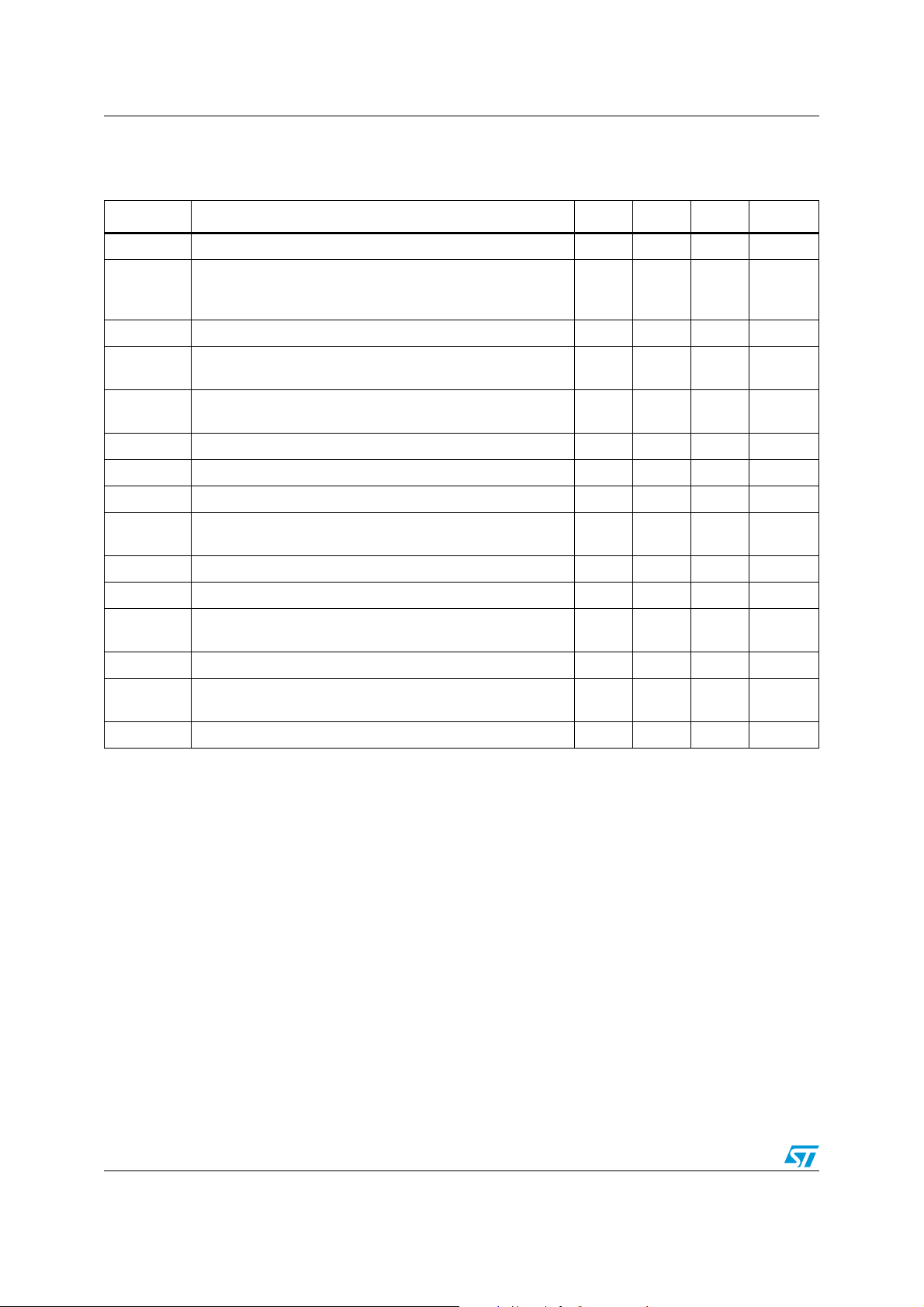
1 Absolute maximum ratings and operating conditions
Table 1. Absolute maximum ratings (AMR)
Symbol Parameter Value Unit
V
CC
V
in
V
in
T
oper
T
stg
T
R
thja
P
ESD
Supply voltage
Input voltage enable & standby pin
Input signal voltage -2.5 to +2.5 V
Operating free-air temperature range -40 to + 85 °C
Storage temperature -65 to +150 °C
Maximum junction temperature 150 °C
j
Thermal resistance junction to ambient
Power dissipation Internally limited
d
Human body model for all pins except outputs
Human body model for all output pins
Machine model 200 V
(1)
(2)
(3)
5.5 V
GND to V
CC
200 °C/W
(4)
2
8
V
kV
Charge device model 1500 V
Latch-up Latch-up immunity 200 mA
Lead temperature (soldering, 10sec) 260 °C
1. All voltage values are measured with respect to the ground pin.
2. The magnitude of the input signal must never exceed VCC + 0.3 V/GND - 0.3 V.
3. The device is protected from overheating by a thermal shutdown mechanism active at 150° C.
4. Exceeding the power derating curves during a long period provokes abnormal operating conditions.
Table 2. Operating conditions
Symbol Parameter Value Unit
V
Supply voltage 3 to 4.8 V
CC
Vicm Common-mode input voltage range From -1.4 to 1.4 V
R
R
R
1. With heatsink surface = 125 mm2.
Line drive load resistor ≥ 5kΩ
LD
Headset drive load resistor ≥ 16 Ω
HD
Thermal resistance junction-to-ambient
thja
(1)
80 °C/W
Doc ID 17913 Rev 1 3/31

Typical application TS4604
2 Typical application
Figure 1. Simplified application schematics in differential configuration setting
R2
2.2 µF
2.2 µF
2.2 µF
2.2 µF
2.2 µF
2.2 µF
2.2 µF
2.2 µF
R1
R1
R1
R1
R1
R1
R1
R1
R2
R2
R2
-LDR
+LDR
R2
-LDL
+LDL
R2
-HPR
+HPR
R2
-HPL
+HPL
R2
OUTLDR
>5 KΩ
OUTLDL
>5 KΩ
TS4604
OUTHPR
16/32 Ω
OUTHPL
16/32 Ω
Thermal shutdown
UVLO
Negative
charged pump
headset
CPHP
1 µF
CNHP
management
Negative
charged pump
line driver
CPLD
1 µF
3 to 4.8 V
PGND
R1= 10 kΩ, R2 = Av x R1
with R2 ≤ 100 k
AGND
AGND
PVCCHP
1 µF
1 µF
PVSSHP
4/31 Doc ID 17913 Rev 1
Powe r
CNLD
PVCCLD
PVSSLD
EUVP
ENHP
ENLD
1 µF
1 µF
3 to 4.8 V
PGND
AM06138

TS4604 Typical application
Table 3. Pin descriptions
Pin number I/O
1 I +LDL Left line driver positive input channel
2 I -LDL Left line driver negative input channel
3 O OUTLDL Left line driver output channel
4 P AGND Analog line driver power ground
5 I ENLD Line driver enable input pin (active high)
6 O PVSSLD Output from line drive charge pump
7 I/O CNLD Line driver charge pump flying capacitor negative terminal
8 I/O CNHP Headset charge pump flying capacitor negative terminal
9 I/O PVSSHP Output from headset drive charge pump
10 I ENHP Headset driver enable input pin (active high)
11 P AGND Headphone analog input power ground
12 O OUTHPL Left headset driver output channel
13 I -HPL Left headset driver negative input channel
14 I +HPL Left headset driver positive input channel
15 I +HPR Right headset driver positive input channel
(1)
Pin name Pin description
16 I -HPR Right headset driver negative input channel
17 O OUTHPR Right headset driver output channel
18 NC Not connected
19 P PGND Headset driver power ground
20 P PVCCHP
Headset driver power supply voltage
(2)
21 I/O CPHP Headset charge pump flying capacitor positive terminal
22 I/O CPLD Line driver charge pump flying capacitor positive terminal
23 P PVCCLD
Line driver power supply voltage
(2)
24 P PGND Line driver power ground
25 I EUVP External undervoltage protection input pin
26 O OUTLDR Right line driver output channel
27 I -LDR Right line driver negative input channel
28 I +LDR Right line driver positive input channel
1. I = input, O = output, P = power
2. PVccHP and PVccLD are internally connected, so PVccHP must be equal to PVccLD.
Doc ID 17913 Rev 1 5/31

Electrical characteristics TS4604
3 Electrical characteristics
Table 4. Common part: VCC = +3.3 V, GND = 0 V, CPhp = CPld = 1 µF, T
amb
= 25°C
(unless otherwise specified)
Symbol Parameters and test conditions Min. Typ. Max. Unit
V
V
IL
V
IH
I
IH
I
IL
F
osc
and V
ENHP
V
and V
ENHP
High level input current (ENHP and ENLD) -1 1 µA
Low level input current (ENHP and ENLD) -1 1 µA
Internal negative voltage switching frequency, all temperature
range
Vup External undervoltage detection threshold 1.15 1.25 1.35 V
Ihyst External undervoltage detection hysteresis current 5 µA
Vhyst Pvcc_HP/LD Internal undervoltage detection hysteresis 200 mV
Pvcc_HP/LD internal undervoltage detection
Vuv l
– power up
– power down
Av Overall external gain (R2 ≤ 100 kΩ, R1 = R2/Av)
Input voltage low 38 40 43 % Vcc
ENLD
Input voltage high 57 60 66 % Vcc
ENLD
400 550 800 kHz
2.8
2.6
0
1
20
10
V
dB
V/V
6/31 Doc ID 17913 Rev 1

TS4604 Electrical characteristics
Table 5. Headset driver part: VCC = +3.3 V, GND = 0 V,
ENHP = V
T
= 25°C (unless otherwise specified)
amb
, ENLD = GND, CPhp = CPld = 1 µF, Av = 1 (R1 = R2 = 10 kΩ),
CC
Symbol Parameters and test conditions Min. Typ. Max. Unit
I
cc
Supply current (no input signal, no load) 5 6.5 mA
Headset overall standby current (no input signal):
V
I
ENHP
V
io
P
o
P
o
THD + N
PSRR
t
WU
t
STBY
Xtalk
SNR Signal-to-noise ratio (A-weighting): R
CMRR
V
N
(1)
CL
= GND
ENHP
= 38% V
V
ENHP
CC
Input offset voltage -7 0 7 mV
Headphone output power:
THD + N = 1% max, f = 1 kHz, BW = 22 kHz, RL = 16 Ω 45 65 mW
Headphone output power:
THD + N = 1% max, f = 1 kHz, BW = 22 kHz, R
= 32 Ω 30 45 mW
L
Total harmonic distortion + noise:
= 16 Ω, Po = 60 mW, f = 20 Hz to 20 kHz, BW = 22 kHz 0.05 %
R
L
Headphone power supply rejection ratio with AC inputs
grounded: f = 217 Hz,V
ripple
= 200 mV
pp
Total wake-up time 30 ms
Standby time 20 µs
Crosstalk headphone to line:
Pout = 50 mW, R
= 16 Ω, f = 20 Hz to 20 kHz -100 dB
L
= 16 Ω, Po = 60 mW 102 dB
L
Common-mode rejection ratio:
f = 20 Hz to 20 kHz, Vic = 200 mVpp -70 dB
Output voltage noise: f = 20 Hz to 20 kHz, A-weighted 7.6 µV
Capacitive load:
= 16 Ω to 100 Ω
R
L
RL > 100 Ω
1. Higher capacitive loads are possible by adding a serial resistor of 47 Ω in the line driver output.
1
90 dB
5
100
400
100
µA
RMS
pF
Doc ID 17913 Rev 1 7/31
Electrical characteristics TS4604
Table 6. Line driver part: VCC = +3.3 V, GND = 0 V, Av = 1 (R1 = R2 = 10 kΩ), ENLD = VCC,
ENHP = GND, CPhp = CPld = 1 µF, R
T
= 25°C (unless otherwise specified)
amb
= 10 kΩ,
L
Symbol Parameters and test conditions Min. Typ. Max. Unit
I
cc
Supply current (no input signal, no load) 5 6.5 mA
Line drive standby current (no input signal)
I
ENLD
V
V
SWING
PSRR
t
WU
t
STBY
= GND
ENLD
= 38% V
V
ENLD
io
Input offset voltage -7 0 +7 mV
CC
Output voltage swing:
= 10 kΩ, CL= 100 pF, THD+N = 0.1% 2.1 Vrms
R
L
Line driver power supply rejection ratio with AC inputs
grounded: f = 217 Hz, V
ripple
= 200 mV
pp
90 dB
Wake-up time from shutdown 30 ms
Standby time 20 µs
5
100
V
SNR Signal-to-noise ratio (A-weighting): Vin = 1.7 Vrms 102 dB
V
N
Output voltage noise: f = 20 Hz to 20 kHz, A-weighted 8 µV
GBw Gain bandwidth product 1 MHz
Sr Slew rate 0.5 V / µs
THD+N
BW = 22 kHz, R
f = 20 Hz to 20 kHz
= 10 kΩ, VO = 1.5 Vrms, Av = 1,
L
0.001 %
CMRR f = 20 Hz to 20 kHz, Vic = 200 mVpp -70 dB
Xtalk
CL
1. Higher capacitive loads are possible by adding a serial resistor of 47 Ω in the line driver output.
Crosstalk channel:
f = 20 Hz to 20 kHz, Vo = 1.5 Vrms, R
(1)
Capacitive load: RL > 5 kΩ 400 pF
= 5 kΩ -120 dB
L
µA
RMS
8/31 Doc ID 17913 Rev 1

TS4604 Characteristics of the line driver
3.03.13.23.33.43.53.63.73.83.94.04.14.24.34.44.54.64.74.8
1.9
2.0
2.1
2.2
2.3
2.4
THD+N=1%
THD+N=0.1%
RL ≥ 5kΩ, F=1kHz
BW<30kHz, Ta=25 C
Line Driver
Output Voltage (Vrms)
Power Supply Voltage Vcc (V)
100 1000
1E-3
0.01
0.1
1
10
F=80Hz
F=1kHz
F=8kHz
RL = 5kΩ to 10kΩ
Vcc = 3.3V to 4.8V, G = 20dB
Inputs = 0° & 180°
BW < 30kHz, Tamb = 25°C
THD+N (%)
Output Voltage (mVrms)
100 1000 10000
1E-3
0.01
0.1
1
Vo=2Vrms
Vo=1.5Vrms
RL = 5kΩ to 10k
Ω
Vcc = 3.3V to 4.8V
G = 20dB, Inputs = 0° & 180
°
Bw < 20kHz, Tamb = 25°C
20k20
THD + N (%)
Frequency (Hz)
4 Characteristics of the line driver
Figure 2. Current consumption vs. power
Figure 3. Output voltage vs. power supply
supply
5.7
5.6
5.5
5.4
5.3
5.2
5.1
5.0
4.9
4.8
4.7
4.6
4.5
Quiescent supply current Icc (mA)
4.4
3.0 3.1 3.2 3.3 3.4 3.5 3.6 3.7 3.8 3.9 4.0 4.1 4.2 4.3 4.4 4.5 4.6 4.7 4.8
No Load; No input signal
Line Driver
Ta=25°C
Power Supply Voltage Vcc (V)
Figure 4. THD+N vs. output power (G=0 dB) Figure 5. THD+N vs. output power (G=20 dB)
10
RL = 5kΩ to 10kΩ
Vcc = 3.3V to 4.8V, G = 0dB
1
Inputs = 0° & 180°
BW < 30kHz, Tamb = 25°C
0.1
THD+N (%)
0.01
1E-3
1E-4
10 100 1000
Output Voltage (mVrms)
Figure 6. THD+N vs. frequency (G=0 dB) Figure 7. THD+N vs. frequency (G=20 dB)
1
RL = 5kΩ to 10k
Vcc = 3.3V to 4.8V
G = 0dB, Inputs = 0° & 180
0.1
Bw < 20kHz, Tamb = 25°C
0.01
THD + N (%)
1E-3
1E-4
Ω
100 1000 10000
Frequency (Hz)
F=1kHz
°
F=8kHz
F=80Hz
Vo=2Vrms
Vo=1.5Vrms
20k20
Doc ID 17913 Rev 1 9/31

Characteristics of the line driver TS4604
100 1000 10000
-130
-120
-110
-100
-90
-80
-70
-60
-50
-40
-30
-20
-10
0
G=0dB
G=20dB
20k
20
Vripple = 200mVpp
Vcc = 3.3V
Inputs = grounded
RL ≥ 5k
Ω
Tamb = 25°C
PSRR (dB)
Frequency (Hz)
1000 10000 100000 1000000 1E7
-80
-70
-60
-50
-40
-30
-20
-10
0
10
Vcc = 3.3V, G=0dB
No load
Tamb = 25°C
Gain (dB)
Frequency (Hz)
Figure 8. CMRR vs. frequency Figure 9. PSRR vs. frequency
0
Δ
Vic = 200mVpp
-10
Vcc = 3.3V
RL ≥ 5k
-20
-30
-40
CMRR (dB)
-50
-60
-70
-80
20
Figure 10. Crosstalk vs. frequency
0
-10
-20
-30
-40
-50
-60
-70
-80
-90
Crosstalk (dB)
-100
-110
-120
-130
-140
-150
Ω
Tamb = 25°C
G=20dB
100 1000 10000
Frequency (Hz)
left to right & right to left channel
Vcc = 3.3V
Vout = 2Vrms
Right to Left & Left to Right
RL ≥ 5k
Ω
Tamb = 25°C
G=20dB
20
100 1000 10000
Frequency (Hz)
G=0dB
G=0dB
20k
Figure 11. Crosstalk vs. frequency
headset to line driver
0
-10
Vcc = 3.3V, G=0dB
-20
RL = 16Ω on HP
-30
Po = 50 mW on HP
-40
LD inputs grounded
-50
Tamb = 25°C
-60
-70
-80
-90
Crosstalk (dB)
-100
-110
-120
-130
-140
20k
-150
20
100 1000 10000
HP to Line Left
Frequency (Hz)
HP to Line Right
20k
Figure 12. Output signal spectrum Figure 13. Frequency response
-20
-30
Vcc = 3.3V, G=0dB
-40
RL=10k
-50
-60
-70
-80
-90
-100
-110
Output Signal (dBV)
-120
-130
-140
-150
-160
10/31 Doc ID 17913 Rev 1
Ω
Tamb = 25°C
100 1000 10000
Frequency (Hz)

TS4604 Characteristics of the headset driver
3.0 3.1 3.2 3.3 3.4 3.5 3.6 3.7 3.8 3.9 4.0 4.1 4.2 4.3 4.4 4.5 4.6 4.7 4.8
0
200
400
600
800
1000
1200
No Load; No input signal
Line Driver
Ta=25°C
Standby current Istby (nA)
Power Supply Voltage Vcc (V)
5 Characteristics of the headset driver
Figure 14. Current consumption vs. power
supply
5.7
5.6
5.5
5.4
5.3
5.2
5.1
5.0
4.9
4.8
4.7
4.6
4.5
Quiescent supply current Icc (mA)
4.4
3.0 3.1 3.2 3.3 3.4 3.5 3.6 3.7 3.8 3.9 4.0 4.1 4.2 4.3 4.4 4.5 4.6 4.7 4.8
No Load; No input signal
Headset Driver
Ta=25°C
Power Supply Voltage Vcc (V)
Figure 16. Output power vs. power supply
(R
= 16 Ω, G = 0 dB)
180
160
140
120
100
80
60
Power Output (mW)
40
20
0
3.0 3.1 3.2 3.33.4 3.5 3.6 3.7 3.83.9 4.0 4.1 4.2 4.3 4. 4 4.5 4.6 4.7 4.8
L
THD+N=10% (180°)
THD+N=1% (0°)
Power Supply Voltage Vcc (V)
THD+N=10% (0°)
THD+N=1% (180°)
RL = 16Ω, F=1kHz
G=0dB
BW<30kHz, Ta=25 C
Headset Driver
Figure 15. Standby current vs. power supply
Figure 17. Output power vs. power supply
(RL = 16 Ω, G = 20 dB)
180
160
THD+N=10% (180°)
140
120
100
80
60
Power Output (mW)
40
20
0
3.0 3.1 3.2 3.33.4 3.5 3.6 3.7 3.83.9 4.0 4.1 4.2 4.3 4. 4 4.5 4.6 4.7 4.8
THD+N=1% (0°)
Power Supply Voltage Vcc (V)
THD+N=10% (0°)
THD+N=1% (180°)
RL = 16Ω, F=1kHz
G=20dB
BW<30kHz, Ta=25 C
Headset Driver
Doc ID 17913 Rev 1 11/31

Characteristics of the headset driver TS4604
0.1 1 10 100
1E-3
0.01
0.1
1
10
F=80Hz
F=1kHz
F=8kHz
RL = 16Ω
Vcc = 3.0V, G = 0dB
Inputs = 0°
BW < 30kHz, Tamb = 25°C
THD+N (%)
Output Power (mW)
0.1 1 10 100
1E-3
0.01
0.1
1
10
F=80Hz
F=1kHz
F=8kHz
RL = 16Ω
Vcc = 3.3V, G = 20dB
Inputs = 0°
BW < 30kHz, Tamb = 25°C
THD+N (%)
Output Power (mW)
Figure 18. Output power vs. power supply
(R
= 32 Ω, G = 0 dB)
180
160
140
120
100
80
60
Power Output (mW)
40
20
0
3.0 3.1 3.2 3.33.4 3.5 3.6 3.7 3.83.9 4.0 4.1 4.2 4.3 4. 4 4.5 4.6 4.7 4.8
L
RL = 32Ω, F=1kHz
G=0dB, 0° & 180°
BW<30kHz, Ta=25 C
Headset Driver
THD+N=10%
THD+N=1%
Power Supply Voltage Vcc (V)
Figure 20. THD+N vs. output power
(R
= 16 Ω, G = 20 dB, V
L
CC
= 3.0 V
inputs in-phase)
10
RL = 16Ω
Vcc = 3.0V, G = 20dB
Inputs = 0°
1
BW < 30kHz, Tamb = 25°C
Figure 19. Output power vs. power supply
(RL = 32 Ω, G = 20 dB)
180
160
140
120
100
80
60
Power Output (mW)
40
20
0
3.0 3.1 3.2 3.33.4 3.5 3.6 3.7 3.83.9 4.0 4.1 4.2 4.3 4. 4 4.5 4.6 4.7 4.8
THD+N=10%
THD+N=1%
RL = 32Ω, F=1kHz
G=20dB, 0° & 180°
BW<30kHz, Ta=25 C
Headset Driver
Power Supply Voltage Vcc (V)
Figure 21. THD+N vs. output power
(RL = 16 Ω, G = 0 dB, V
CC
= 3.0 V
inputs in-phase)
Figure 22. THD+N vs. output power
0.1
THD+N (%)
0.01
1E-3
0.1 1 10 100
(R
L
Output Power (mW)
= 16 Ω, G = 0 dB, V
F=8kHz
F=80Hz
CC
inputs out-of-phase)
10
RL = 16
Ω
Vcc = 3.0V, G = 0dB
Inputs = 180
1
BW < 30kHz, Tamb = 25°C
0.1
THD+N (%)
0.01
1E-3
0.1 1 10 100
°
F=8kHz
F=1kHz
F=80Hz
Output Power (mW)
F=1kHz
= 3.3 V
Figure 23. THD+N vs. output power
(RL = 16 Ω, G = 20 dB, V
inputs in-phase)
CC
= 3.3 V
12/31 Doc ID 17913 Rev 1

TS4604 Characteristics of the headset driver
0.1 1 10 100
1E-3
0.01
0.1
1
10
F=80Hz
F=1kHz
F=8kHz
RL = 16Ω
Vcc = 3.3V, G = 0dB
Inputs = 180°
BW < 30kHz, Tamb = 25°C
THD+N (%)
Output Power (mW)
0.1 1 10 100
1E-4
1E-3
0.01
0.1
1
10
F=80Hz
F=1kHz
F=8kHz
RL = 32Ω
Vcc = 3.0V, G = 0dB
Inputs = 0° & 180°
BW < 30kHz, Tamb = 25°C
THD+N (%)
Output Power (mW)
Figure 24. THD+N vs. output power
(RL = 16 Ω, G = 0 dB, VCC = 3.3 V
inputs in-phase)
10
RL = 16Ω
Vcc = 3.3V, G = 0dB
Inputs = 0°
1
BW < 30kHz, Tamb = 25°C
0.1
THD+N (%)
0.01
1E-3
0.1 1 10 100
F=80Hz
Output Power (mW)
F=8kHz
Figure 26. THD+N vs. output power
(RL = 16 Ω, G = 20 dB, VCC = 4.8 V,
inputs in-phase)
10
RL = 16
Ω
Vcc = 4.8V, G = 20dB
Inputs = 0
1
BW < 30kHz, Tamb = 25°C
0.1
THD+N (%)
°
F=8kHz
F=1kHz
Figure 25. THD+N vs. output power
(RL = 16 Ω, G = 0 dB, VCC = 3.3 V, inputs
out-of-phase)
Figure 27. THD+N vs. output power
(RL = 16 Ω, G = 0 dB, VCC = 4.8 V
inputs in-phase)
10
RL = 16
Ω
Vcc = 4.8V, G = 0dB
1
0.1
THD+N (%)
0.01
Inputs = 0
BW < 30kHz, Tamb = 25°C
°
F=8kHz
0.01
1E-3
0.1 1 10 100
Output Power (mW)
Figure 28. THD+N vs. output power
(R
= 16 Ω, G = 0 dB, VCC = 4.8 V
L
inputs out-of-phase)
10
RL = 16
Ω
Vcc = 4.8V, G = 0dB
Inputs = 180
1
BW < 30kHz, Tamb = 25°C
0.1
THD+N (%)
0.01
1E-3
0.1 1 10 100
°
F=1kHz
Output Power (mW)
F=80Hz
F=80Hz
F=1kHz
F=8kHz
1E-3
1E-4
0.1 1 10 100
F=1kHz
F=80Hz
Output Power (mW)
Figure 29. THD+N vs. output power
(RL = 32 Ω, VCC = 3.0 V, G = 0 dB)
Doc ID 17913 Rev 1 13/31

Characteristics of the headset driver TS4604
0.1 1 10 100
1E-4
1E-3
0.01
0.1
1
10
F=80Hz
F=1kHz
F=8kHz
RL = 32
Ω
Vcc = 3.3V, G = 0dB
Inputs = 0° & 180
°
BW < 30kHz, Tamb = 25°C
THD+N (%)
Output Power (mW)
0.1 1 10 100
1E-4
1E-3
0.01
0.1
1
10
F=80Hz
F=1kHz
F=8kHz
RL = 32Ω
Vcc = 4.8V, G = 0dB
Inputs = 0° & 180°
BW < 30kHz, Tamb = 25°C
THD+N (%)
Output Power (mW)
100 1000 10000
1E-3
0.01
0.1
1
Po=1mW
Po=15mW
RL = 16
Ω
Vcc = 3.0V to 4.8V
G = 0dB, Inputs = 0° & 180
°
Bw < 20kHz, Tamb = 25°C
20k20
THD + N (%)
Frequency (Hz)
Figure 30. THD+N vs. output power
(R
= 32 Ω, VCC = 3.0 V, G = 20 dB)
L
10
RL = 32Ω
Vcc = 3.0V, G = 20dB
Inputs = 0° & 180°
1
BW < 30kHz, Tamb = 25°C
0.1
THD+N (%)
0.01
1E-3
0.1 1 10 100
Output Power (mW)
F=8kHz
F=80Hz
Figure 32. THD+N vs. output power
(R
= 32 Ω, VCC = 3.3 V, G = 20 dB)
L
10
RL = 32Ω
Vcc = 3.3V, G = 20dB
Inputs = 0° & 180°
1
BW < 30kHz, Tamb = 25°C
Figure 31. THD+N vs. output power
(RL = 32 Ω, VCC = 3.3 V, G = 0 dB)
F=1kHz
Figure 33. THD+N vs. output power
(RL = 32 Ω, VCC = 4.8 V, G = 0 dB)
0.1
THD+N (%)
0.01
1E-3
0.1 1 10 100
Output Power (mW)
Figure 34. THD+N vs. output power
(R
= 32 Ω, VCC = 4.8 V, G = 20 dB)
L
10
RL = 32Ω
Vcc = 4.8V, G = 20dB
Inputs = 0° & 180°
1
BW < 30kHz, Tamb = 25°C
0.1
THD+N (%)
0.01
1E-3
0.1 1 10 100
14/31 Doc ID 17913 Rev 1
Output Power (mW)
F=8kHz
F=80Hz
F=1kHz
Figure 35. THD+N vs. frequency
(RL = 16 Ω, G = 0 dB)
F=8kHz
F=1kHz
F=80Hz

TS4604 Characteristics of the headset driver
100 1000 10000
1E-3
0.01
0.1
1
Po=1mW
Po=10mW
RL = 32Ω
Vcc = 3.0V to 4.8V
G = 0dB, Inputs = 0° & 180°
Bw < 20kHz, Tamb = 25°C
20k20
THD + N (%)
Frequency (Hz)
Figure 36. THD+N vs. frequency
(R
= 16 Ω, G = 20 dB)
L
1
RL = 16Ω
Vcc = 3.0V to 4.8V
G = 20dB, Inputs = 0° & 180°
Bw < 20kHz, Tamb = 25°C
THD + N (%)
0.01
1E-3
0.1
100 1000 10000
Frequency (Hz)
Po=1mW
Po=15mW
Figure 38. THD+N vs. frequency
(R
= 32 Ω, G = 20 dB)
L
1
RL = 32
Ω
Vcc = 3.0V to 4.8V
G = 20dB, Inputs = 0° & 180
Bw < 20kHz, Tamb = 25°C
0.1
THD + N (%)
0.01
1E-3
100 1000 10000
°
Po=1mW
Po=10mW
Frequency (Hz)
Figure 37. THD+N vs. frequency
(RL = 32 Ω, G = 0 dB)
20k20
Figure 39. CMRR vs. frequency (headset)
0
Δ
Vic = 200mVpp
-10
Vcc = 3.3V
-20
RL ≥ 16
Ω
Tamb = 25°C
-30
-40
-50
CMRR (dB)
-60
-70
-80
-90
20k20
-100
20
100 1000 10000
G=20dB
G=0dB
Frequency (Hz)
20k
Figure 40. PSSR vs. frequency (headset) Figure 41. Crosstalk vs. frequency
(left to right, Pout = 50 mW)
0
-10
Vcc = 3.3V
-20
Pout = 50mW, G=0dB
-30
RL = 16
-40
Tamb = 25°C
-50
-60
-70
-80
-90
Crosstalk (dB)
-100
-110
-120
-130
-140
-150
20
Ω
Left to Right
100 1000 10000
Frequency (Hz)
PSRR (dB)
-10
-20
-30
-40
-50
-60
-70
-80
-90
-100
-110
-120
-130
0
20
Vripple = 200mVpp
Vcc = 3.3V
Inputs = grounded
RL ≥ 16
Ω
Tamb = 25°C
G=20dB
100 1000 10000
Frequency (Hz)
G=0dB
20k
Doc ID 17913 Rev 1 15/31
Right to Left
20k

Characteristics of the headset driver TS4604
Figure 42. Crosstalk vs. frequency
(left to right, Pout = 35 mW)
0
-10
Vcc = 3.3V
-20
Pout = 35mW, G=0dB
-30
RL = 32
-40
-50
-60
-70
-80
-90
Crosstalk (dB)
-100
-110
-120
-130
-140
-150
20
Ω
Tamb = 25°C
Left to Right
100 1000 10000
Frequency (Hz)
Figure 44. Frequency response
10
0
-10
-20
-30
-40
Gain (dB)
-50
Vcc = 3.3V, G=0dB
-60
No load
-70
Tamb = 25°C
-80
1000 10000 100000 1000000 1E7
Frequency (Hz)
Right to Left
Figure 43. Crosstalk vs. frequency
line driver to headset
0
-10
Vcc = 3.3V
-20
Vout = 2Vrms on LD, G=0dB
-30
RL = 10kΩ on LD
-40
HP inputs = ground
-50
Tamb = 25°C
-60
-70
-80
-90
Crosstalk (dB)
20k
-100
-110
-120
-130
-140
-150
20
LD to HP left
100 1000 10000
Frequency (Hz)
LD to HP right
20k
16/31 Doc ID 17913 Rev 1

TS4604 Application information
p
6 Application information
6.1 General description
The TS4604 is a stereo headset driver and a ground-referenced stereo audio line driver. To
save energy, each audio path, line driver or headphone can be independently set to standby
mode.
The headphone delivers up to 100 mW into a 16 Ω load, and the line driver drives up to
2 Vrms into 5k or more. The gain can be set up to 20 dB by changing the values of the
external gain resistors.
The outputs of the headphone and line driver are protected against overloads. Overloads
can occur when the outputs are short-circuited between them or to Gnd or to V
also an internal thermal shutdown activated at 150°C (typical) and deactivated at 120°C
(typical).
To remove the bulky output DC blocking capacitor and maximize the output swing of the
amplifier, the TS4604 embeds a low noise internal negative supply. All amplifiers are
supplied between a positive voltage +Vp and a negative voltage -Vn. With this architecture,
the output voltage is centered on 0 V, allowing the swing of the output voltage between the
positive and negative rail, as depicted in Figure 45.
. There is
CC
Both the line driver and headset driver use this architecture.
Figure 45. TS4604 voltage f
In-
In+
or one channel
Negative
supply
-
+
Vreg
Vcc
Vreg
+Vp
-Vn
Out
+V
0 V
-Vn
Note: The PVSSHP and PVSSLD voltages are generated internally by the internal negative
supply. To avoid damage to the TS4604, do not connect an external power supply on
the PVSSHP and PVSSLD pins.
AM06139
Doc ID 17913 Rev 1 17/31

Application information TS4604
6.2 Use of ceramic capacitors
We advise using ceramic capacitors for the decoupling, flying or tank capacitors because of
their low ESR properties. The rated voltage of the ceramic capacitor, however, is an
important parameter to take into consideration.
A 1 µF/6.3 V capacitor used at 4.8 V DC typically loses about 40% of its value. In fact, with a
4.8 V power supply voltage, the decoupling value is about 0.6 µF instead of 1 µF. Because
the decoupling capacitor influences the THD+N in the medium-to-high frequency region, this
capacitor variation becomes decisive. In addition, less decoupling means higher overshoots,
which can be problematic if they reach the power supply's AMR value (5.5 V).
This is why it is recommend to use a 1 µF/10 V/X5R or a 2.2 µF/6.3 V/X5R, or a new kind of
ceramic capacitor with a low DC bias variation rated at 6.3 V.
If a 1 µF/10 V ceramic capacitor is used, at 4.8 V the capacitance will be 0.82 µF.
If a 2.2 µF/6.3 V ceramic capacitor is used, at 4.8 V the capacitance will be 1.1 µF.
6.3 Flying and tank capacitor for the internal negative supply
The TS4604 embeds two independent internal negative supplies as shown in Figure 1.
Each of them requires two capacitors to work properly (a flying and a tank capacitor). The
internal negative supply capacitor must be correctly selected to generate an efficient
negative voltage.
Two flying capacitors (CHP and CLD) of 1 µF each with low ESR are recommended for
internal negative power supply operation.
● CHP between pins 8 and 21.
● CLD between pins 7 and 22.
Two tank capacitors (CPvss_HP and CPvss_LD) of 1 µF each with low ESR are
recommended for internal negative power supply energy storage.
● CPvss_HP between pin 9 and ground.
● CPvss_LD between pin 6 and ground.
An X5R dielectric for capacitor tolerance should be used. In order to take into consideration
the ΔC/ΔV variation of this type of dielectric (see Section 6.2 above), we also recommend:
● a 10 V DC rating voltage for 4.8 V power supply operation.
● a 6.3 V DC rating operation for 3.3 V power supply operation.
These capacitors must be placed as close as possible to the TS4604 to minimize parasitic
inductance and resistance that have a negative impact on the audio performance.
6.4 Power supply decoupling capacitor (Cs)
A 1 µF decoupling capacitor (Cs) with low ESR is mandatory for the positive power supply
X5R dielectric for capacitor tolerance behavior. In order to take into consideration the ΔC/ΔV
variation of this type of dielectric (see Section 6.2 above), it is also recommended to use:
● a 10 V DC rating voltage for 4.8 V power supply operation.
● a 6.3 V DC rating operation for 3.3 V power supply operation.
18/31 Doc ID 17913 Rev 1

TS4604 Application information
These capacitors must be placed as close as possible to the TS4604 to minimize parasitic
inductance and resistance that have a negative impact on the audio performance.
6.5 Input coupling capacitor (Cin)
An input coupling capacitor (Cin) might be used for TS4604 operation to block any DC
component of the audio signal.
Cin starts to have an effect in the low frequency region. Cin forms with Rin a high-pass filter
with a -3 dB cut-off frequency.
1
Fc 3dB–()
Example
A differential input gain as shown in Figure 46 on page 20 with the gain equalling 0 dB
(Rin = 10 kΩ, Rfd = 10 kΩ) and an input capacitor of 2.2 µF gives:
----------------------------------------- -
2.π Rin Cin⋅⋅
Hz()=
--------------------------------------------------------------- - 7.2H z==
Fc
⋅⋅
2.π 10000 2.2 e10
1
The high-pass filter has a -3 dB cut-off frequency at 7.2 Hz in this case.
6.6 Range of the gain setting resistors
The TS4604 can be use in different configurations, as shown in figures 46, 47 and 48.
The gain is given by the external resistors Rfd divided by Rin. The feedback resistor Rfd
does not exceed 100 kΩ for closed-loop stability reasons.
Ta bl e 7 gives the recommended resistor values and the gain for different types of
application.
Table 7. Recommended resistors values
Rin Rfd Differential gain Inverting gain Non-inverting gain
Ω 10 kΩ 0 dB 0 dB 6 dB
10 k
10 k
Ω 20 kΩ 6 dB 6 dB 10 dB
Ω 50 kΩ 14 dB 14 dB 16 dB
10 k
Ω 47 kΩ 20 dB 20 dB 21 dB
4.7 k
10 k
Ω 100 kΩ 20 dB 20 dB 21 dB
6–
Doc ID 17913 Rev 1 19/31

Application information TS4604
Figure 46. Example of a TS4604 differential input
Rfd
Cin
Rin
Vin-
Vin+
Cin
Rin
Rfd
Figure 47. Example of a TS4604 inverting input
Rfd
Cin
Vin-
Rin
Vout
AM06140
Vout
AM06141
Figure 48. Example of a TS4604 non-inverting input
Cin
Vin+
Cin
20/31 Doc ID 17913 Rev 1
Rin
Rfd
Vout
Rx
AM06142

TS4604 Application information
6.7 Performance of CMRR
When the TS4604 is used in differential mode (Figure 46), because of the resistor matching
the CMRR can have important variations.
To minimize these variations, we recommend using the same kind of resistor (same
tolerance).
The following equation is valid for frequencies ranging from DC to about kHz. The equation
is simplified by neglecting the ΔR² terms. ΔR is the tolerance value as a percentage.
100
CMRR 20
----------- -
4ΔR
It is extremely important to correctly match the resistors to obtain a good CMRR.
All the tests have been performed with resistors with a tolerance value of 0.1%.
Example:
With ΔR = 1% the minimum CMRR would be 34 dB.
With ΔR = 0.1% the minimum CMRR would be 54 dB.
Rfd
⎛⎞
1
--------- -+
Rin
dB()log⋅≈
⎝⎠
6.8 Internal and external undervoltage detection
The TS4604 embeds two UVLOs: one internal and one external.
6.8.1 Internal UVLO
The internal UVLO monitors the power supply via pins PVCC_HP (20) and PVCC_LD(23).
The threshold is set to 2.8 V with a 200 mV hysteresis. If the power supply decreases to
2.6 V, the TS4604 switches to standby mode. To switch the device on again, the power
supply voltage must increase to above 2.8 V.
Refer to Ta bl e 4 for the tolerance of the UVLO voltage.
6.8.2 External UVLO
The Ex_UVP pin (25) is an external undervoltage detection input that can be used to start
up or shutdown the TS4604 by applying the correct voltage value. A 1.25 V internal
precision voltage is used as a reference to monitor the voltage applied to the Ex_UPVP pin.
To set a desired shutdown threshold and hysteresis for the application, a resistor divider can
be calculated as follows.
Vu vp 1.25V
Vhyst≈ 5μAR3
R1 R2+()
-------------------------- -
⋅=
R1
R2
⎛⎞
------- - 1+
⋅⋅
⎝⎠
R1
with the condition R3>>R1//R2.
Doc ID 17913 Rev 1 21/31

Application information TS4604
For example, to obtain Vuvp = 3.3 V with a hysteresis of 200 mV:
● R1 = 1 kΩ
● R2 = 1.6 kΩ
● R3 = 15 kΩ
Figure 49. External UVLO
Vcc
External sense voltage
1.6 k
R2
5 µA
15 k
R3
1 k
R1
Figure 50. Hysteresis of the external UVLO
Icc
VHyst
+
-
Precision
band gap
1.25 V
TS4604
AM06143
Vuvp
When the external sense voltage (ESV) increases, the TS4604 stays in standby mode until
the EUVP pin reaches 1.25 V (voltage across the divider R1, R2). At this point, the TS4604
starts, as does the internal 5 µA current source connected to the EUVP pin. Thanks to this
5 µA current, a voltage drop is created across the R3 resistor.
22/31 Doc ID 17913 Rev 1
External sense
voltage
AM06144

TS4604 Application information
To switch the TS4604 back to standby, the voltage across the divider R1, R2 has to be lower
than 1.25 V - VHyst × R1/(R1 + R2). The ESV can be an external voltage or simply the
power supply voltage PVcc_LD/HD.
6.9 2nd order Butterworth low-pass filter
The TS4604 can also be configured as a low-pass filter to be driven directly by a DAC
output. It can be used, for example, as a 2nd order low-pass filter, with either a differential
input or a single-ended input.
Figure 51 and Figure 52 depict these two kinds of application and represent a multiple
feedback 2nd order low-pass filter.
An AC-coupling capacitor should be added to block any DC component from the source,
which helps to reduce the output DC offset to a minimum.
Figure 51. Multi-feedback filter with
Cin
Vin-
Vin+
Cin
differential input
Rin
C2
Rin
R1
R1
Rfd
C1
C1
Figure 52. Multi-feedback filter with single-
ended input
Rfd
Vout
Cin
Vin-
Rin
C2
R1
C1
Vout
Rfd
AM06145
AM06146
Example 2nd-order multi-feedback filter in differential mode
Figure 53 shows a filter in differential mode with a cut-off frequency at 30 kHz (configured as
per the values in Ta bl e 8 , which proposes various filter options using a differential input).
Doc ID 17913 Rev 1 23/31

Application information TS4604
Figure 53. Frequency response 2nd-order MFB filter
5
4
3
2
1
0
-1
-2
-3
Gain (dB)
-4
-5
R1 = Rin = 10kΩ,
-6
Rfd = 24kΩ,
-7
C1 = 680pF,
-8
C2 = 120pF,
-9
1 10 100 1000 10000 100000
Frequency (Hz)
Table 8. Recommended values for 2nd order low-pass filter
Low-pass filter Rin R1 Rfd C1 C2
25 kHz 10 k
30 kHz 10 k
Ω 10 kΩ 15 kΩ 1 nF 200 pF
Ω 10 kΩ 24 kΩ 680 pF 120 pF
6.10 ESD protection and compliance
To provide excellent ESD immunity, an audio line IPAD
EMIF04-EAR02M8) can be added at the output of the TS4604 (Figure 54).
By adding the IPAD, the TS4604 complies with the standard IEC 61000-4-2 level 4 on the
external pins.
● OUT_HPL and OUT_HPR for the headphone driver.
● OUT_LDL and OUT_LDR for the Line driver.
(a)
(STMicroelectronics reference
a. Copyright ST Microelectronics.
24/31 Doc ID 17913 Rev 1

TS4604 Application information
Figure 54. TS4604 with IPAD for ESD immunity
InR-
InR+
InL-
InL+
TS4604
-
+
-
+
OUT_R
OUT_L
6.11 Pop-&-click circuitry
Thanks to the internal negative supply the headphone and line driver outputs are referred to
ground without the need for bulky in-series capacitors. As a result, the pop created by these
bulky capacitors is eliminated. In addition, the TS4604 includes a pop-&-click circuitry that
suppresses any residual pop on the outputs, thus enabling the outputs to be virtually pop-&click-free.
A1 A2
B2
Gnd
Gnd
C1
IPAD
C2
OUT_R
Gnd
OUT_L
AM06147
6.12 Start-up phase
To further improve the pop-&-click performance, two important points must be taken into
account during the start-up phase.
Input capacitor
During the start up phase, as long as the AC input coupling capacitors are not fully charged,
we suggested to remain the EN_LD and En_HP and/or Ext_UVP pin low.
The constant time for an RC filter is given by:
τ Rin Cin⋅=
We can consider that the input capacitor Cin will be charged at 95% of its maximum value
at:
T3τ=
Doc ID 17913 Rev 1 25/31

Application information TS4604
With a gain set at G = 0 dB, a Rin = 10 kΩ and Cin = 2.2 µF, to charge Cin to 95% of its final
value, 66 ms are necessary.
Wake-up time of the TS4604
The TS4604 needs 30 ms to become fully operational (see Ta bl e 5 and Ta bl e 6).
The total startup sequence with the settings described being 66 ms, and since the TS4604
needs 30 ms to wake up, the Enable pin for the line driver and/or headphone can be set high
36 ms after the power supply has reached its normal value (Figure 55).
With a lower input capacitance, the startup phase is quicker.
Figure 55. Power-up/down sequence
Supply
Supply ramp
EN_xx
36 ms
Vout
66 ms
6.13 Layout recommendations
Particular attention must be given to the correct layout of the PCB traces and wires between
the amplifier, load and power supply.
The power and ground traces are critical since they must provide adequate energy and
grounding for all circuits. Good practice is to use short and wide PCB traces to minimize
voltage drops and parasitic inductance.
Proper grounding guidelines help improve audio performances, minimize crosstalk between
channels, and prevent switching noise from coupling into the audio signal. It is also
recommended to use a large-area and multi-via ground plane to minimize parasitic
impedance.
Connect all the V
The copper traces that connect the output pins to the load and supply pins should be as
wide as possible to minimize the trace resistances.
tracks (PVCCLD and PVCCHP) to one point one the board.
CC
30 ms
AM06148
The gain setting resistors must be placed as close as possible to the input in order to
minimize the parasitic capacitors on these inputs pins.
26/31 Doc ID 17913 Rev 1

TS4604 Package information
7 Package information
In order to meet environmental requirements, ST offers these devices in different grades of
ECOPACK
specifications, grade definitions and product status are available at: www.st.com.
ECOPACK
®
packages, depending on their level of environmental compliance. ECOPACK®
®
is an ST trademark.
Doc ID 17913 Rev 1 27/31

Package information TS4604
7.1 TSSOP28 package
Figure 56. TSSOP28 pitch 0.65 mm mechanical drawing
Table 9. TSSOP28 pitch 0.65 mm mechanical data
Dimensions
Ref.
Min. Typ. Max. Min. Typ. Max.
A1.200.047
A1 0.05 0.15 0.002 0.006
A2 0.80 1.00 1.05 0.031 0.039 0.041
b 0.19 0.30 0.007 0.011
c 0.09 0.20 0.003 0.008
D 9.60 9.70 9.80 0.378 0.382 0.386
E 6.20 6.40 6.60 0.244 0.252 0.260
E1 4.30 4.40 4.50 0.170 0.173 0.177
e 0.65 0.026
L 0.45 0.60 0.75 0.018 0.024 0.030
L1 1.00 0.040
k0 8
aaa 0.10 0.004
Millimeters Inches
28/31 Doc ID 17913 Rev 1

TS4604 Ordering information
8 Ordering information
Table 10. Order codes
Part number
TS4604IPT -40°C, +85°C External TSSOP28 4604
Temperature
range
Gain Package Marking
Doc ID 17913 Rev 1 29/31

Revision history TS4604
9 Revision history
Table 11. Document revision history
Date Revision Changes
27-Oct-2010 1 Initial release.
30/31 Doc ID 17913 Rev 1

TS4604
Please Read Carefully:
Information in this document is provided solely in connection with ST products. STMicroelectronics NV and its subsidiaries (“ST”) reserve the
right to make changes, corrections, modifications or improvements, to this document, and the products and services described herein at any
time, without notice.
All ST products are sold pursuant to ST’s terms and conditions of sale.
Purchasers are solely responsible for the choice, selection and use of the ST products and services described herein, and ST assumes no
liability whatsoever relating to the choice, selection or use of the ST products and services described herein.
No license, express or implied, by estoppel or otherwise, to any intellectual property rights is granted under this document. If any part of this
document refers to any third party products or services it shall not be deemed a license grant by ST for the use of such third party products
or services, or any intellectual property contained therein or considered as a warranty covering the use in any manner whatsoever of such
third party products or services or any intellectual property contained therein.
UNLESS OTHERWISE SET FORTH IN ST’S TERMS AND CONDITIONS OF SALE ST DISCLAIMS ANY EXPRESS OR IMPLIED
WARRANTY WITH RESPECT TO THE USE AND/OR SALE OF ST PRODUCTS INCLUDING WITHOUT LIMITATION IMPLIED
WARRANTIES OF MERCHANTABILITY, FITNESS FOR A PARTICULAR PURPOSE (AND THEIR EQUIVALENTS UNDER THE LAWS
OF ANY JURISDICTION), OR INFRINGEMENT OF ANY PATENT, COPYRIGHT OR OTHER INTELLECTUAL PROPERTY RIGHT.
UNLESS EXPRESSLY APPROVED IN WRITING BY AN AUTHORIZED ST REPRESENTATIVE, ST PRODUCTS ARE NOT
RECOMMENDED, AUTHORIZED OR WARRANTED FOR USE IN MILITARY, AIR CRAFT, SPACE, LIFE SAVING, OR LIFE SUSTAINING
APPLICATIONS, NOR IN PRODUCTS OR SYSTEMS WHERE FAILURE OR MALFUNCTION MAY RESULT IN PERSONAL INJURY,
DEATH, OR SEVERE PROPERTY OR ENVIRONMENTAL DAMAGE. ST PRODUCTS WHICH ARE NOT SPECIFIED AS "AUTOMOTIVE
GRADE" MAY ONLY BE USED IN AUTOMOTIVE APPLICATIONS AT USER’S OWN RISK.
Resale of ST products with provisions different from the statements and/or technical features set forth in this document shall immediately void
any warranty granted by ST for the ST product or service described herein and shall not create or extend in any manner whatsoever, any
liability of ST.
ST and the ST logo are trademarks or registered trademarks of ST in various countries.
Information in this document supersedes and replaces all information previously supplied.
The ST logo is a registered trademark of STMicroelectronics. All other names are the property of their respective owners.
© 2010 STMicroelectronics - All rights reserved
STMicroelectronics group of companies
Australia - Belgium - Brazil - Canada - China - Czech Republic - Finland - France - Germany - Hong Kong - India - Israel - Italy - Japan -
Malaysia - Malta - Morocco - Philippines - Singapore - Spain - Sweden - Switzerland - United Kingdom - United States of America
www.st.com
Doc ID 17913 Rev 1 31/31
 Loading...