


ST TIP120, TIP121, TIP122, TIP125, TIP126 User Manual
...
现货库存、技术资料、百科信息、热点资讯,精彩尽在鼎好!
COMPLEMENTARY SILICON POWER
■ STMicroelectronics P REF ERRED
SALESTYPES
DESCRIPTION
The TIP120, TIP121 and TIP122 are silicon
Epitaxial-Base NPN power transistors in
monolithic Darlington configuration mounted in
Jedec TO-220 plastic package. They are intented
for use in power linear and switching applications.
The complementary PNP types are TIP125,
TIP126 and TIP127, respectively.
TIP120/121/122
TIP125/126/127
DARLINGTON TRANSISTORS
3
2
1
TO-220
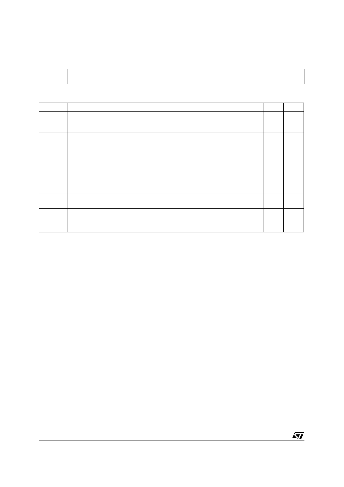
INTER NAL SCH E M ATI C DIAG RA M
R1 Typ. = 5 KΩ R2 Typ. = 150 Ω
ABSOLUTE MAXIMUM RATINGS
Symbol Parameter Value Unit
NPN TIP120 TIP121 TIP122
PNP TIP125 TIP126 TIP127
V
V
V
I
P
T
* For PNP types voltage and current values are negative.
Collector-Base Voltage (IE = 0) 60 80 100 V
CBO
Collector-Emitter Voltage (IB = 0) 60 80 100 V
CEO
Emitter-Base Voltage (IC = 0) 5 V
EBO
I
Collector Current 5 A
C
Collector Peak Current 8 A
CM
Base Current 0.1 A
I
B
Total Dissipation at T
tot
T
Storage Temperature -65 to 150
stg
Max. Operating Junction Temperature 150
T
j
case
amb
≤ 25 oC
≤ 25 oC
65
2
W
W
o
C
o
C
March 2000
1/4
TIP120/TIP121/TI P122/TIP125/ TIP126/T IP127
THERMAL DATA
R
thj-case
R
thj-amb
Thermal Resistance Junction-case Max
Thermal Resistance Junction-ambient Max
1.92
62.5
o
C/W
o
C/W
ELECTRICAL CHARACTERISTICS (T
= 25 oC unless otherwise specified)
case
Symbol Parameter Test Conditions Min. Typ. Max. Unit
I
CEO
Collector Cut-off
Current (I
= 0)
B
for TIP120/125 V
for TIP121/126 V
for TIP122/127 V
I
CBO
Collector Cut-off
Current (I
= 0)
B
for TIP120/125 V
for TIP121/126 V
for TIP122/127 V
I
EBO
V
CEO(sus)
Emitter Cut-off Current
(I
= 0)
C
* Collector-Emitter
Sustaining Voltage
(I
= 0)
B
= 5 V 2 mA
V
EB
I
= 30 mA
C
for TIP120/125
for TIP121/126
for TIP122/127
V
* Collector-Emitter
CE(sat)
Saturation Voltage
V
* Base-Emitter Voltage IC = 3 A VCE = 3 V 2.5 V
BE(on)
IC = 3 A IB = 12 mA
I
= 5 A IB = 20 mA
C
hFE* DC Current Gain IC = 0.5 A VCE = 3 V
I
= 3 A VCE = 3 V
C
∗ Pulsed: Pulse duration = 300 µs, duty cycle < 2 %
For PNP types voltage and current values are negative.
= 30 V
CE
= 40 V
CE
= 50 V
CE
= 60 V
CB
= 80 V
CB
= 100 V
CB
60
80
100
1000
1000
0.5
0.5
0.5
0.2
0.2
0.2
2
4
mA
mA
mA
mA
mA
mA
V
V
V
V
V
2/4