

2-stage RF power amplifier with LPF based on the
PD85006L-E and STAP85050 RF power transistors
Features
■ Excellent thermal stability
■ Frequency: 400 - 470 MHz
■ Supply voltage: 13.6 V
■ Output power: 50 W
■ Current: < 10 A
■ Input power: 20 dBm
■ Harmonics level < -45 dBc
■ Output low-pass filter
■ Power detection
■ Temperature sensor
Description
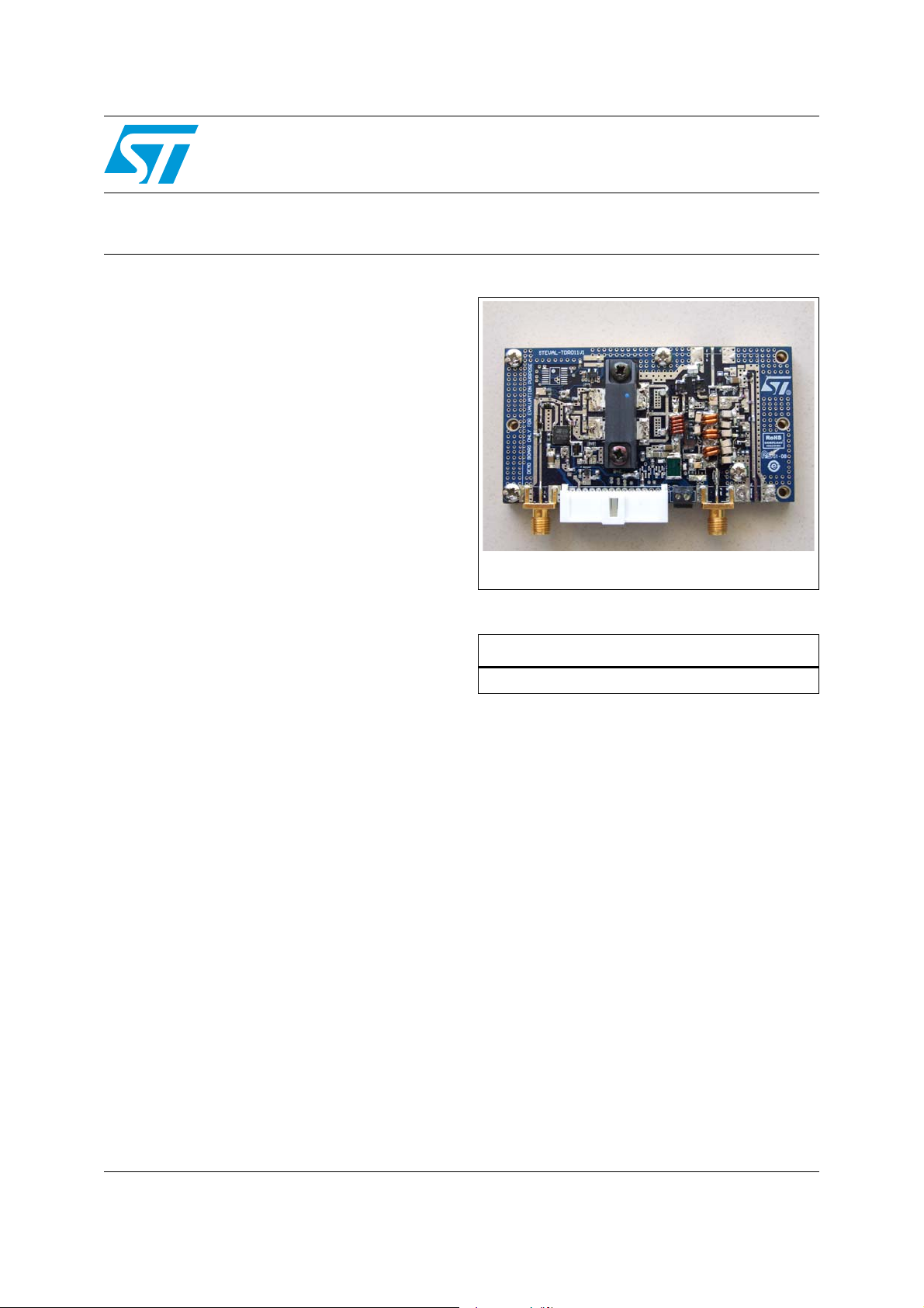
The STEVAL-TDR011V1 demonstration board is
a two-stage 50 W RF power amplifier which
includes an output LPF (low-pass filter) for
harmonics rejection. It also features power
detection and a temperature sensor.
STEVAL-TDR011V1
L = 88.8 mm, W = 47.5 mm
Table 1. Device summary
Order code
STEVAL-TDR011V1
The main purpose of the board is to demonstrate
the functioning and performance of the
PD85006L-E and the STAP85050 devices from
the LdmoST plastic family of RF power
transistors.
The application is specifically designed for 2-way
analog and digital mobile radios.
March 2010 Doc ID 17340 Rev 1 1/12
www.st.com
12

Contents STEVAL-TDR011V1
Contents
1 Electrical data . . . . . . . . . . . . . . . . . . . . . . . . . . . . . . . . . . . . . . . . . . . . . . 3
1.1 Maximum ratings . . . . . . . . . . . . . . . . . . . . . . . . . . . . . . . . . . . . . . . . . . . . 3
1.2 Electrical characteristics . . . . . . . . . . . . . . . . . . . . . . . . . . . . . . . . . . . . . . . 3
2 Typical performance . . . . . . . . . . . . . . . . . . . . . . . . . . . . . . . . . . . . . . . . . 4
3 Circuit layout . . . . . . . . . . . . . . . . . . . . . . . . . . . . . . . . . . . . . . . . . . . . . . . 9
4 Schematic diagram . . . . . . . . . . . . . . . . . . . . . . . . . . . . . . . . . . . . . . . . . 10
5 Revision history . . . . . . . . . . . . . . . . . . . . . . . . . . . . . . . . . . . . . . . . . . . 11
2/12 Doc ID 17340 Rev 1
STEVAL-TDR011V1 Electrical data
1 Electrical data
1.1 Maximum ratings
Table 2. Absolute maximum ratings
Symbol Parameter Value Unit
V
T
CASE
DD
I
D
T
A
Supply voltage
Drain current 12 A
Operating case temperature -10 to +85 °C
Max. ambient temperature +55 °C
1. Value related to the voltage regulator LD2980ABM50TR used in the application.
1.2 Electrical characteristics
(1)
16 V
TA = +25 °C, VDD = 13.6 V, V
APC
adjusted
Table 3. Electrical specifications
Symbol Test conditions Min. Typ. Max. Unit
Freq. Frequency range 400 470 MHz
P
I
TOTAL
Gain @ P
Harmonics @ P
@ P
IN
@ P
= 50 W 20 dBm
OUT
= 50 W 10 A
OUT
= 50 W 27 dB
OUT
= 50 W -50 / -74 dBc
OUT
Doc ID 17340 Rev 1 3/12

Typical performance STEVAL-TDR011V1
0
10
20
30
40
50
60
70
370 380 390 400 410 420 430 440 450 460 470 480 490
Frequency (MHz)
Pout (W)
3
4
5
6
7
8
9
10
Id (A)
Pout Id
Vdd = 13.6V
Idq = 200 + 2x 200mA
Pin = 20dBm
20
22
24
26
28
30
32
370 380 390 400 410 420 430 440 450 460 470 480 490
Frequency (MHz)
Gain (dB)
Vdd = 13.6V
Idq = 200 + 2x 200mA
Pin = 20dBm
20
25
30
35
40
45
50
55
60
65
380 390 400 410 420 430 440 450 460 470 480 490
Frequency (MHz)
Efficiency (%)
Vdd = 13.6V
Idq = 200 + 2x 200mA
Pin = 20dBm
-10
-8
-6
-4
-2
0
380 390 400 410 420 430 440 450 460 470 480 490
Frequency (MHz)
IRL (dB)
Vdd = 13.6V
Idq = 200 + 2x 200mA
Pin = 20dBm
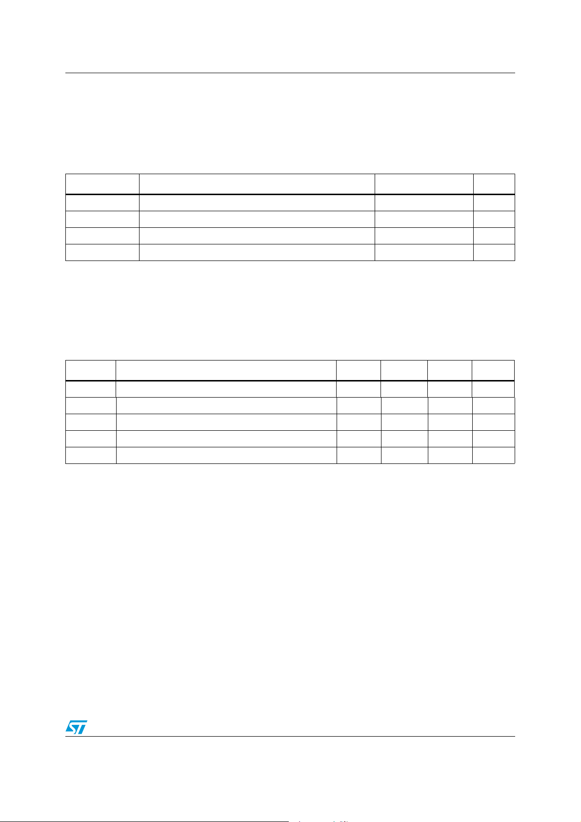
2 Typical performance
Figure 1. Output power and drain current vs.
Figure 3. Efficiency vs. frequency Figure 4. Input return loss vs. frequency
frequency
TDR011V1_01
TDR011V1-03
Figure 2. Gain vs. frequency
TDR011V1_02
TDR011V1-04
4/12 Doc ID 17340 Rev 1
STEVAL-TDR011V1 Typical performance
24
26
28
30
32
34
36
38
40
42
44
46
10 15 20 25 30 35 40 45 50
Pout (W)
Gain (dB)
380 MHz 400 MHz 420 MHz 440 MHz 460 MHz 470 MHz
Vdd = 13.6V Idq = 200 + 2x 200mA
-80
-70
-60
-50
-40
-30
-20
-10
0
400 410 420 430 440 450 460 470
Frequency (MHz)
Harmonics (dB)
H2 H3
Vdd = 13.6V
Idq = 200 + 2x 200mA
Pout = 50W
0
0.5
1
1.5
2
2.5
30 32 34 36 38 40 42 44 46
Pout (dBm)
Vp1 - Vp2 (V)
380 MHz 400 MHz 430 MHz
460 MHz 470 MHz
0
0.5
1
1.5
2
2.5
3
380 390 400 410 420 430 440 450 460 470
Frequency (MHz)
Vp1 - Vp2 (V)
Po= 47dBm Po= 43dBm Po= 37dBm
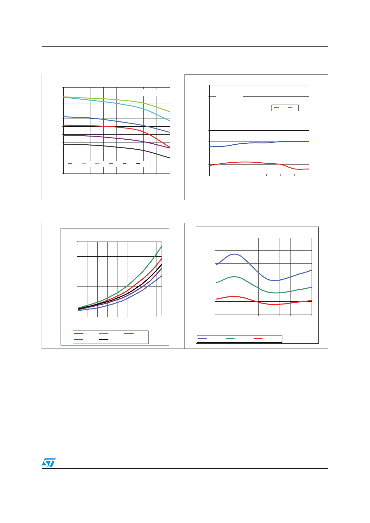
Figure 5. Gain vs. output power Figure 6. Harmonics
TDR011V1_05
Figure 7. Vp1-Vp2 vs. output power Figure 8. Vp1-Vp2 vs. output power
TDR011V1_06
TDR011V1-08
Doc ID 17340 Rev 1 5/12
TDR011V1-09

Typical performance STEVAL-TDR011V1
0
2
4
6
8
10
380 400 420 440 460 480
Frequency (MHz)
Id (A)
0
20
40
60
80
100
T (°C)
Id Temp erature
NO FAN ONLY HEATSINK
Figure 9. Drain current and temperature
record on PCB surface
TDR011V1_07
Table 4. Component list
Designator Value Qty Manufacturer Order code Size/package
C1 10 µF 1 Murata GRM31CR61E106KA12 1206
C1f, C2f, C3f 3.9 pF 3 ATC ATC 100B 3R9JW 1111
C1p, C2p 5 pF 2 Murata GRM1885C1H5R0CZ01 0603
C1t 10 pF 1 Murata GRM1885C1H100JA01 0603
C2 100 pF 1 Murata GRM42-6 COG 101J 50 1206
C2a, C3a, C5a, C6a 1 pF 4 Murata GRM1885C1H1R0CZ01 0603
C2t 0.1 µF 1 Murata GRM1885C1H101JA01 0603
C3 0.1 µF 1 Murata GRM188F5H1104ZA01 0603
C3p, C5p 1 pF 2 ATC ATC 100B 1R0JW 1111
C4, C9 0.1 µF 2 Murata GRM188F51H104ZA01 0603
C4p, C6p 9.1 pF 2 ATC ATC 100B 9R1JW 1111
C5, C8, C8a, C10,
C11, C12
100 pF 6 Murata GRM1885C1H101JA01 0603
C5f, C6f 5.6 pF 2 ATC ATC 100B 5R6JW 1111
C6, C7 47 pF 2 Murata GRM1885C1H470JA01 0603
C9a 4.7 µF 1 Murata GRM31CF51H475ZA01 1206
C13 18 pF 1 Murata GRM1885C1H180JA01 0603
C14 15 pF 1 Murata GRM1885C1H150JA01 0603
C14a, C14b 18 pF 2 Murata GRM1885C1H180JZ01B 0603
C15 5.6 pF 1 Murata GRM1885C1H5R6DZ01 0603
C16 39 pF 1 Murata GRM1885C1H390JA01 0603
6/12 Doc ID 17340 Rev 1

STEVAL-TDR011V1 Typical performance
Table 4. Component list (continued)
Designator Value Qty Manufacturer Order code Size/package
C17, C18 150 pF 2 Murata GRM1885C1H151JA01 0603
C19, C20 39 pF 2 Murata ERF1DM5C1H390JD01B 0505
C21 33 pF 1 Murata MA59C0G330J150 0505
C22a 12 pF 1 Murata ERF1DM5C1H120JD01B 0505
C22b 4.7 pF 1 Murata MA59C0G4R7C150 0505
Caf 100 pF 1 ATC ATC 100B 101JW 1111
Ci 2.2 µF 1 Murata GRM188R71A225KE15 0603
Co 1 µF 1 Murata GRM188R71C105KA12D 0603
CS1 1
Integration
Associates, Inc
IA2410 SOT-23 5-pin
CS2 1
Integration
Associates, Inc
IA4210 SOT-23 5-pin
D1a, D2a 2 MACOM MA4P7101F-1072T
D1p, D2p 2 STMicroelectronics BAS70-04WFILM SOT-323
D3a 1 STMicroelectronics MA4P7436-1141T SOD-323
D4a 1 MACOM MA4P275-1141T SOD-323
DB 1 MACOM IA4910 TSSOP 16-pin
J1 1
Integration
Associates, Inc
55935-1410 14-pin, single row
Jb 1 Molex L04220211000 2-pin, 3.5 mm pitch
2 pins -
JP
step
2.54 mm
-90
1 LMI 5-826947-0
o
L1 33 nH 1 Tyco Electronics AS080447-33N
L1a 470 nH 1 Korin Electronics 0805LS-471X_BC 0805LS
L1f, L2f, L3f 9.3 nH 3 Coilcraft AS120252-9R3N
L2
12.55
nH
1 Korin Electronics 1606-10 1606
L2a, L3a 6.8 nH 2 Coilcraft 0603HC-6N8X_BW 0603HC
L3 5.4 nH 1 Coilcraft 0906-5 0906
L4 5.4 nH 1 Coilcraft 0906-4 0906
L5, L6 5 nH 2 Korin Electronics A02T
PD1, PD2 2 STMicroelectronics
STAP85050 (or 2x
PD85035S-E)
PSO-10
PD85006L-E 1 STMicroelectronics PD85006L-E PFLAT
TL1 1 W=0.9 mm, L=2 mm
TL2 1 W=0.9 mm, L=5 mm
Doc ID 17340 Rev 1 7/12

Typical performance STEVAL-TDR011V1
Table 4. Component list (continued)
Designator Value Qty Manufacturer Order code Size/package
TL3, TL15 2 W=0.9 mm, L=8 mm
TL4, TL6, TL16 3 W=0.9 mm, L=4 mm
TL5 1 W=0.9 mm, L=1.2 mm
TL9 1 W=0.9 mm, L=5.7 mm
TL10, TL11, TL18 3 W=0.9 mm, L=6 mm
TL12, TL13 2 W=0.9 mm, L=6.5 mm
TL14, TL17 2 W=0.9 mm, L=2.5 mm
R1, R8, R9 220 Ω 3 Tyco Electronics 0603
R1a, R2, R7, R10 1 kΩ 4 Murata PVZ2A102C04B00
R1p, R2p, R3p, R4p 20 kΩ 4 Tyco Electronics 0603
R1t 100 kΩ 1 Tyco Electronics 0603
R3, R6, R11 2.2 kΩ 3 Tyco Electronics 0603
R4, R5 15 kΩ 2 Tyco Electronics 0603
R5p, R6p, R7p,
RG3, RG4
50 Ω 5 Tyco Electronics 0603
R12 330 Ω 1 Tyco Electronics 0603
R13, R14 1 Ω 2 Tyco Electronics 0603
RF ant, RF in, RF
out PA, to receiver
Johnson 142-0701-801 60 Mils
RG1, RG2 200 Ω 2 Tyco Electronics 0603
RO1 5 kΩ 2 Tyco Electronics 0603
RO2 2 kΩ 2 Tyco Electronics 0603
Thermal Sensor 1 STMicroelectronics STLM20 SOT323-5
Voltage regulator 1 STMicroelectronics LD2980ABM50TR SOT-23-5
8/12 Doc ID 17340 Rev 1

STEVAL-TDR011V1 Circuit layout
3 Circuit layout
Figure 10. Test fixture component layout
Doc ID 17340 Rev 1 9/12

Schematic diagram STEVAL-TDR011V1
4 Schematic diagram
Figure 11. STEVAL-TDR011V1 schematic diagram
14
13
12
Pinout
11
10
9
J1
8
7
6
5
4
3
2
Jb
1
2
Vdd
R1 R8
VGS0
VGS1
Ci
1
Vi
VR
GND
2
INHIBIT
3
Vo
Co
5
+ 5 V
1
R9
C3
GND
GND
1
GND
INHIBIT
GND
nc
INHIBIT
nc
nc
VP2
VP1
nc
V(T)
nc
nc
nc
VGS1
VGS0
L1
C2
C1
C9
C8
R5
R2 R7
C4
2
JP
R3 R6
R4
C5
C10
L2
R10
C11
TL12
TL10
C6 C7
C14b
R11
R12
TL17
C22b
C22a
L5
TL15 TL16
C21
C19
TL9 TL1 4
PD1
R14
R13
C17
C16
TL5 TL6
C15
C14a
TL4
PD85006L
TL18
L6
Tx/Rx
C1p
Vo1
R1p
ower Detector
P
Vo2
R3p R2p
C20
TL11 TL13
PD2
VP2
C18
TL3
C12
RF In
D1p D2p
Vo1
R4p
C2p
VP1
L4
C14
TL2
L3
TL1
C13
ilter
F
Caf
C4p
C1f
C3p
C2f
C5p
C6p
R7p R6p R5p
C3f
hermal Sensor
T
+ 5V
V(T)
R1t
Thermal Sensor
C2t
Ver 0.2
Cif
L1f
C5f
L2f
C6f
L3f
RF Ant
C1t
10/12 Doc ID 17340 Rev 1

STEVAL-TDR011V1 Revision history
5 Revision history
Table 5. Document revision history
Date Revision Changes
31-Mar-2010 1 Initial release.
Doc ID 17340 Rev 1 11/12

STEVAL-TDR011V1
Please Read Carefully:
Information in this document is provided solely in connection with ST products. STMicroelectronics NV and its subsidiaries (“ST”) reserve the
right to make changes, corrections, modifications or improvements, to this document, and the products and services described herein at any
time, without notice.
All ST products are sold pursuant to ST’s terms and conditions of sale.
Purchasers are solely responsible for the choice, selection and use of the ST products and services described herein, and ST assumes no
liability whatsoever relating to the choice, selection or use of the ST products and services described herein.
No license, express or implied, by estoppel or otherwise, to any intellectual property rights is granted under this document. If any part of this
document refers to any third party products or services it shall not be deemed a license grant by ST for the use of such third party products
or services, or any intellectual property contained therein or considered as a warranty covering the use in any manner whatsoever of such
third party products or services or any intellectual property contained therein.
UNLESS OTHERWISE SET FORTH IN ST’S TERMS AND CONDITIONS OF SALE ST DISCLAIMS ANY EXPRESS OR IMPLIED
WARRANTY WITH RESPECT TO THE USE AND/OR SALE OF ST PRODUCTS INCLUDING WITHOUT LIMITATION IMPLIED
WARRANTIES OF MERCHANTABILITY, FITNESS FOR A PARTICULAR PURPOSE (AND THEIR EQUIVALENTS UNDER THE LAWS
OF ANY JURISDICTION), OR INFRINGEMENT OF ANY PATENT, COPYRIGHT OR OTHER INTELLECTUAL PROPERTY RIGHT.
UNLESS EXPRESSLY APPROVED IN WRITING BY AN AUTHORIZED ST REPRESENTATIVE, ST PRODUCTS ARE NOT
RECOMMENDED, AUTHORIZED OR WARRANTED FOR USE IN MILITARY, AIR CRAFT, SPACE, LIFE SAVING, OR LIFE SUSTAINING
APPLICATIONS, NOR IN PRODUCTS OR SYSTEMS WHERE FAILURE OR MALFUNCTION MAY RESULT IN PERSONAL INJURY,
DEATH, OR SEVERE PROPERTY OR ENVIRONMENTAL DAMAGE. ST PRODUCTS WHICH ARE NOT SPECIFIED AS "AUTOMOTIVE
GRADE" MAY ONLY BE USED IN AUTOMOTIVE APPLICATIONS AT USER’S OWN RISK.
Resale of ST products with provisions different from the statements and/or technical features set forth in this document shall immediately void
any warranty granted by ST for the ST product or service described herein and shall not create or extend in any manner whatsoever, any
liability of ST.
ST and the ST logo are trademarks or registered trademarks of ST in various countries.
Information in this document supersedes and replaces all information previously supplied.
The ST logo is a registered trademark of STMicroelectronics. All other names are the property of their respective owners.
© 2010 STMicroelectronics - All rights reserved
STMicroelectronics group of companies
Australia - Belgium - Brazil - Canada - China - Czech Republic - Finland - France - Germany - Hong Kong - India - Israel - Italy - Japan -
Malaysia - Malta - Morocco - Philippines - Singapore - Spain - Sweden - Switzerland - United Kingdom - United States of America
www.st.com
12/12 Doc ID 17340 Rev 1
 Loading...