


45W/2Ω BRIDGECAR RADIO AMPLIFIER
HIGHPOWER CAPABILITY:
- 65W/2ΩMAX
- 60W/2ΩEIAJ
- 45W/2Ω @V
DIFFERENTIAL INPUTS (EITHER SINGLE
ENDED OR DIFFERENTIAL INPUT SIGNALS
ARE ACCEPTED)
MINIMUMEXTERNALCOMPONENTCOUNT:
- NO BOOTSTRAPCAPACITORS
- NO BOUCHEROT CELLS
- INTERNALLYFIXEDGAIN (26dB)
- NO SVR CAPACITOR
ST.-BYFUNCTION (CMOS COMPATIBLE)
AUTOMATIC MUTE DURING TURN-ON/OFF
AUTOMUTEATMINIMUMSUPPLY
VOLTAGEDETECTION
SYNCHRONIZING PIN FOR SIMULTANEOUS
TURN-ONIN MULTI-DEVICEAPPLICATIONS
NO AUDIBLE POP DURING MUTE AND ST-
BY OPERATIONS
DiagnosticFacilities:
CLIPPINGDETECTOR
Figure 1: Test And ApplicationCircuit
S= 14.4V,f = 1KHz,d = 10%
TDA7396
WITH DIAGNOSTICFACILITY
Multiwatt11
ORDERING NUMBER: TDA7396
SHORTCIRCUIT
OPENLOAD
THERMALSHUTDOWN
PROTECTIONS:
SHORT CIRCUIT (TO GND, TO V
THELOAD)
VERYINDUCTIVE LOADS
CHIP OVER-TEMPERATURE
LOADDUMP
OPENGND
ESD
ACROSS
S,
+V
S
1000µF
Vref
10KΩ
TO µC
7
5
4
GND
100nF
OUT+
OUT-
CD-DIA
0.22µF
39
CM
10µF
2
1
8
11
TDA7396
10 6
RS
51KΩ
IN+
0.22µF
IN-
STANDBY
TO µCorV
October 1998
This is advanced informationon a new product now in development or undergoing evaluation. Details are subject to change without notice.
S
D93AU004
1/11

TDA7396
DESCRIPTION
The TDA7396 is a BRIDGE class AB audio power
amplifier especially intended for car radio High
Power applications.
The 2Ω power capability together with the possibility to operate either in DIFFERENTIAL INPUT
MODE or SINGLE ENDED INPUT MODE makes
it suitable for boostersand high end car radio ap-
Figure 2:
BlockDiagram
STANDBYTHRESHOLD
1
IN-
2
IN+
V
CC1VCC2
39
+
-
ICM
500Ω
500Ω
-
+
gm
REFERENCES
10K
COMMON
MODE
-
+
V
CC/2
10K
plications.
The exclusive fully complementary output stage
and the internallyfixed gain configurationdrop the
externalcomponent count.
The on board clipping detector allows easy implementationof gain compressionsystems.
The diagnostics facility allows to detect any mistakes during car radio set assembly and wiring in
the car.
CIRCUIT
SHORT
DUMP &
THERMAL
PROTECTION
5
POWER AMP
LTS
POWER AMP
DETECT
THD
V=f
(Tj)
LTS
DISABLE
OUT-
4
DIAGN
CD
7
OUT+
+
-
MUTE THRESHOLD
MUTE SYNC GND STANDBY
PIN CONNECTION (Topview)
TAB CONNECTED TO PIN 6
THERMAL DATA
PROGRAMMABLE
CURRENT CIRCUIT
1011 8
11
10
DIAGNOSTIC
CIRCUIT
6
D94AU107
MUTE
SYNC
9
8
7
6
5
4
3
2
1
D93AU003A
+V
S
STAND-BY
OUT+
GND
OUT-
CD-DIA (CLIPPING DETECTOR - DIAG.)
+V
S
IN+
IN-
Symbol Description Value Unit
R
th j-case
Thermal Resistance Junction-case Max 1.5
2/11
C/W
°
TDA7396
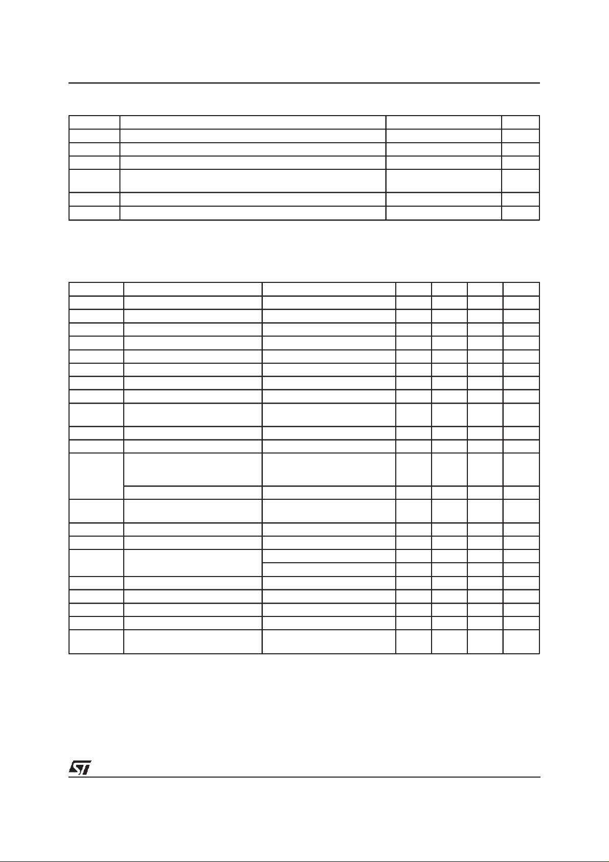
ABSOLUTE MAXIMUM RATINGS
Symbol Parameter Value Unit
V
V
V
PEAK
P
T
stg,Tj
OP
I
O
tot
DC Supply Voltage 28 V
S
Operating Supply Voltage 18 V
Peak Supply Voltage (t = 50ms) 50 V
Output Peak Current repetitive (f > 10Hz)
Output Peak Current non repetitive
Power Dissipation (T
=85°C) 43 W
CASE
6
7
Storage and Junction-Case -40 to 150 °C
A
A
ELECTRICAL CHARACTERISTICS (VS= 14.4V; RL=2Ω, f = 1KHz, T
=25°C, unless otherwise
amb
specified)
Symbol Parameter Test Condition Min. Typ. Max. Unit
V
S
I
q
V
OS
I
SB
I
SBin
V
SBon
V
SBoff
ATT
ST-BY
R
EXT/RS
I
Min
A
M
P
O
d Distortion P
G
V
f
H
R
IN
E
IN
CMRR Input Common Mode Rejection f = 1KHz; V
SVR Supply Voltage Rejection R
CDL Clipping Detection Level 0.5 %
T
sd
Supply Voltage Range 8 18 V
Total Quiescent Current 100 mA
Output Offset Voltage 150 mV
ST-BY Current V
ST-BY Input Bias Current V
= 1.5V 100 µA
ST-BY
=5V 10 µA
ST-BY
ST-BY On Threshold Voltage 1.5 V
ST-BY Off threshold Voltage 3.5 V
ST-BY Attenuation 90 dB
Mute Resistor Ratio for External
(see Application Circuit of fig. 4) 0.63 0.69 V
Mute Control
Mute Input Bias Current V
=5V 10
MUTE
Mute Attenuation 90 dB
RMS Output Power d = 10%
d=1%
d = 10%; R
EIAJ Output Power V
= 13.7V 60 W
S
= 0.1 to 20W
O
P
= 0.1 to 15W; RL=4Ω
O
=4Ω
L
45
35
27
0.06
0.03
Voltage Gain 25 26 27 dB
High Frequency rolloff PO= 1W; -3dB 75 KHz
Input Impedance Differential 60 K
Single Ended 55 K
Input Noise Voltage Rg=0Ω;f= 22Hz to 22KHz 4 mV
= 1Vrms 70 dB
IN
=0Ω;Vr= 1Vrms 60 dB
g
Absolute Thermal Shutdown
160 dB
Junction Temperature
A
µ
W
W
W
%
%
Ω
Ω
3/11

TDA7396
FUNCTIONAL DESCRIPTION
Pin Function Description
1, 2 INPUTS
4 CD - DIA
5, 7 OUTPUTS
8 STAND-BY
10 SYNC
11 MUTE
The input stage is a high impedance differential type also capable of operation in single
ended mode with one input capacitively coupled to the signalGND. the impedance seen
by the inverting and non inverting input pins must be matched.
The TDA7396 is equipped with a diagnostics circuitry able to detect the following events:
-Clipping in the Output Signal
-Thermal Shutdown
-Open Load (before turn-on)
-Shorted Output: to GND, to Vs, across the load (afterturn-on)
The CD-DIA(open collector) pin gives out the diagnostics signal (low during clipping or
output fault condition).
The device does not work as long as the faulty condition holds; the normal operation is
automatically restored after the fault removal.
The output stage is a bridge type able to drive loads as high as 2Ω.
It consists of two class AB fully complementary PNP/NPN stages fully protected.
A rail to rail output voltage swing is achieved with no need of bootstrap capacitors.
No external compensation is necessary.
The device features a ST-BY functionwhich shuts down all the internal bias supplies
when the ST-BY input is low.
In ST-BY mode the amplifier sinks a small current (in the range of few µA).
When the ST-BY pin is high the IC becomes fully operational.
A resistor (R
current that flows into C
required to bias the amplifier.
a) The pin will have a capacitor(C
automatic Mute duringturn on/off is provided to prevent noisy transients
b) If a independent Mute function is needed,an external transistor circuit (see fig. 4) may
be connected to thispin; 1% precision resistors have to be used for R
to reach the fixed limits 0.63
) has to be connect between pin 10 and GND in orderto program the
S
capacitor (pin 11). Thevalues of CMand RSdetermine the time
M
) tied to GND to set the MUTE/STAND-BY time. An
M
≤ R
EXT/RS
≤0.69
EXT/RS
in to order
Figure 3: ApplicationCircuit with ExternalMute Control
0.22µF
39
2
1
TDA7396
8
11
CM
10 6
RS
TO µCorV
TO µC
IN+
0.22µF
IN-
STANDBY
S
REXT
7
5
4
GND
100nF
OUT+
OUT-
CD-DIA
1000µF
Vref
10KΩ
D93AU007
+V
S
TO µC
4/11

Figure 4: Quiescent Current vsSupply Voltage Figure5: EIAJ power vs SupplyVoltage
RL=2
=4
R
L
TDA7396
Ω
Ω
Figure 6: OutputPowervs SupplyVoltage(R
=2
R
Ω
L
L
=2Ω)
f = 1KHz
Figure 8: OutputPowervs SupplyVoltage(RL=4Ω)
R
=4Ω
L
f = 1KHz
Figure7:
Distortionvs Frequency(R
= 14.4V
V
S
R
=2
Ω
L
P
= 18W
O
f (Hz)
Figure9: Distortionvs Frequency(R
V
= 14.4V
S
R
=4
Ω
L
P
= 15W
O
=2Ω)
L
=4Ω)
L
f (Hz)
5/11

TDA7396
Figure 10: SupplyVoltageRejection vsFre-
quency
V
= 14.4V
S
V
= 1Vrms
r
R
=2
Ω
L
R
=0
g
f (Hz)
Figure 12: TotalPowerDiss i pation&Efficienc yvs.
=2Ω)
L
V
= 14.4V
S
R
=2
Ω
L
f = 1KHz
OutputPower(R
Figure11: CommonMode Rejection vs. Fre-
quency
= 14.4V
V
S
V
= 1Vrms
cm
R
=2
Ω
L
=0
R
g
f (Hz)
Figure13:
TotalPowerDissipati on& Efficiencyvs.
OutputPower (R
=4Ω)
L
= 14.4V
V
S
R
=4Ω
L
f = 1KHz
6/11

Figure 14: ApplicationCircuit
C2 0.22µF
IN+
C1 0.22µF
39
2
C5 100nF
OUT+
7
+V
S
C4 1000µF
TDA7396
IN-
1
TDA7396
J1
V
S
SW1
D93AU108
Figure 15: P.C.Board and Component Layout (1:1 scale)
ST-BY
C3
10µF
8
11
10 6
R2
51KΩ
5
4
GND
OUT-
CD-DIA
R1 15KΩ
100nF
5V
R3
100KΩ
TO µC
C6
7/11

TDA7396
CLIPPINGDETECTION & DIAGNOSTICS
(see fig. 16)
An active pull-down circuit is provided to signal
out the occurrence of any of the conditions described later. In order to use this function,the CDDIA pin (#4) has to be resistively connected to a
positivevoltagereference (between 5V and Vs).
A) ClippingDetection
Current is sunk whenever the output clipping distortion level reaches a fixed 0.5% threshold; this
function allows gain compressionfacility when the
amplifier is overdriven.
B) OutputFault Diagnostics
Current is sunk as soon as one of the following
output faultsis recognized:
- short-circuit to GND
- short-circuit to Vs
- short-circuit across the load(after turn-on)
- openload (before turn-on)
The diagnostics signal remains steadily on until
the fault is removed.
All the output fault conditions (listed above) can
be distinguished from the clipping detection (A)
because of theirdifferenttime duration.
THERMAL WARNING (seefig. 17)
Thermal protection has been implemented in ac-
cordance to a new principle involving different
steps:
1) Thermalfoldback(LinearThermal Shutdown)
2) Shutdown with soft restart(Absolute Thermal
Shutdown)
As long as the junction temperature remains below the preset threshold (140°C) the IC delivers
the full power. Once the threshold has been
reached, a thermal foldback starts limiting the output signal level; the output power is then reduced,
thus decreasingalso the temperaturewithout output signal interruption (LTS). Supposing the thermal foldback does not reduce the junction temperatureto a safe level, a completeshutdown will
occurat 160°C (ATS).
Soft restart avoids large voltage disturbance
across the loudspeaker, due to the presence of
high input signals when the IC comes out of thermal shutdown.
Currentis sunkfrom the CD-DIA pin (#4)whenthe
thermal protection is acting.The voltage at pin #4
bounces back and forth (depending on the amplifier input signal magnitude) during the linear thermal intervention(LTS) and stays low (sinking current) after the amplifier has been eventually
shut-down(Absolute Thermal Shutdown)
Figure 16:
CLIPPING
DETECTOR/
DIAGNOSTICS
OUTPUT
(pin 4)
8/11
ClippingDetection & DiagnosticsWaveforms
Vo
CLIPPING
0
NORMAL OPERATION FAULT DIAGNOSTICS NORMAL OPERATION
S/C TO GND
D93AU005A

Figure 17: ThermalProtection& Diagnostic Waveforms
MAX
OUTPUT
VOLTAGE
SWING
0
140°C 160°C
DIAGNOSTICS
OUTPUT
(pin 4)
LINEAR
THERMAL
SHUT DOWN
ABS
THERMAL
SHUTDOWN
D93AU006A
TDA7396
9/11

TDA7396
DIM.
MIN. TYP. MAX. MIN. TYP. MAX.
A5
B 2.65 0.104
C 1.6 0.063
D 1 0.039
E 0.49 0.55 0.019 0.022
F 0.88 0.95 0.035 0.037
G 1.45 1.7 1.95 0.057 0.067 0.077
G1 16.75 17 17.25 0.659 0.669 0.679
H1 19.6 0.772
H2 20.2 0.795
L 21.9 22.2 22.5 0.862 0.874 0.886
L1 21.7 22.1 22.5 0.854 0.87
L2 17.4 18.1 0.685 0.713
L3 17.25 17.5 17.75 0.679 0.689 0.699
L4 10.3 10.7 10.9 0.406 0.421 0.429
L7 2.65 2.9 0.104 0.114
M 4.25 4.55 4.85 0.167 0.179 0.191
M1 4.73 5.08 5.43 0.186 0.200 0.214
S 1.9 2.6 0.075 0.102
S1 1.9 2.6 0.075 0.102
Dia1 3.65 3.85 0.144 0.152
mm inch
0.197
0.886
OUTLINE AND
MECHANICAL DATA
Multiwatt11 V
10/11

TDA7396
Information furnished is believed to be accurate and reliable. However, STMicroelectronics assumes no responsibility for the consequences
of use of such information nor for any infringement of patents or other rights of third parties which may result from its use. No license is
granted by implication or otherwise under any patent or patent rights of STMicroelectronics. Specification mentioned in this publication are
subject to change without notice. This publication supersedes and replaces all information previously supplied. STMicroelectronics products
are not authorized for use as critical components in life support devices or systems without express written approval of STMicroelectronics.
Australia - Brazil - Canada - China - France - Germany - Italy - Japan - Korea - Malaysia - Malta- Mexico - Morocco -The Netherlands-
Singapore - Spain - Sweden - Switzerland- Taiwan - Thailand - United Kingdom - U.S.A.
The ST logo is a registered trademark of STMicroelectronics
1998 STMicroelectronics – Printed in Italy – All Rights Reserved
STMicroelectronics GROUP OF COMPANIES
http://www.st.com
11/11
 Loading...