

T1235H, T1250H
High temperature 12 A Snubberless™ Triacs
Features
■ Medium current Triac
■ 150 °C max. T
■ Low thermal resistance with clip bonding
■ Very high 3 quadrant commutation capability
■ Packages are RoHS (2002/95/EC) compliant
■ UL certified (ref. file E81734)
turn-off commutation
j
Applications
Especially designed to operate in high power
density or universal motor applications such as
vacuum cleaner and washing machine drum
motor, these 12 A Triacs provide a very high
switching capability up to junction temperatures of
150 °C.
The heatsink can be reduced, compared to
traditional Triacs, according to the high
performance at given junction temperatures.
Description
Available in through-hole or surface mount
packages, the T1235H and T1250H Triac series
are suitable for general purpose mains power ac
switching.
By using an internal ceramic pad, the T12xxH-6I
provides voltage insulation (rated at 2500 V rms).
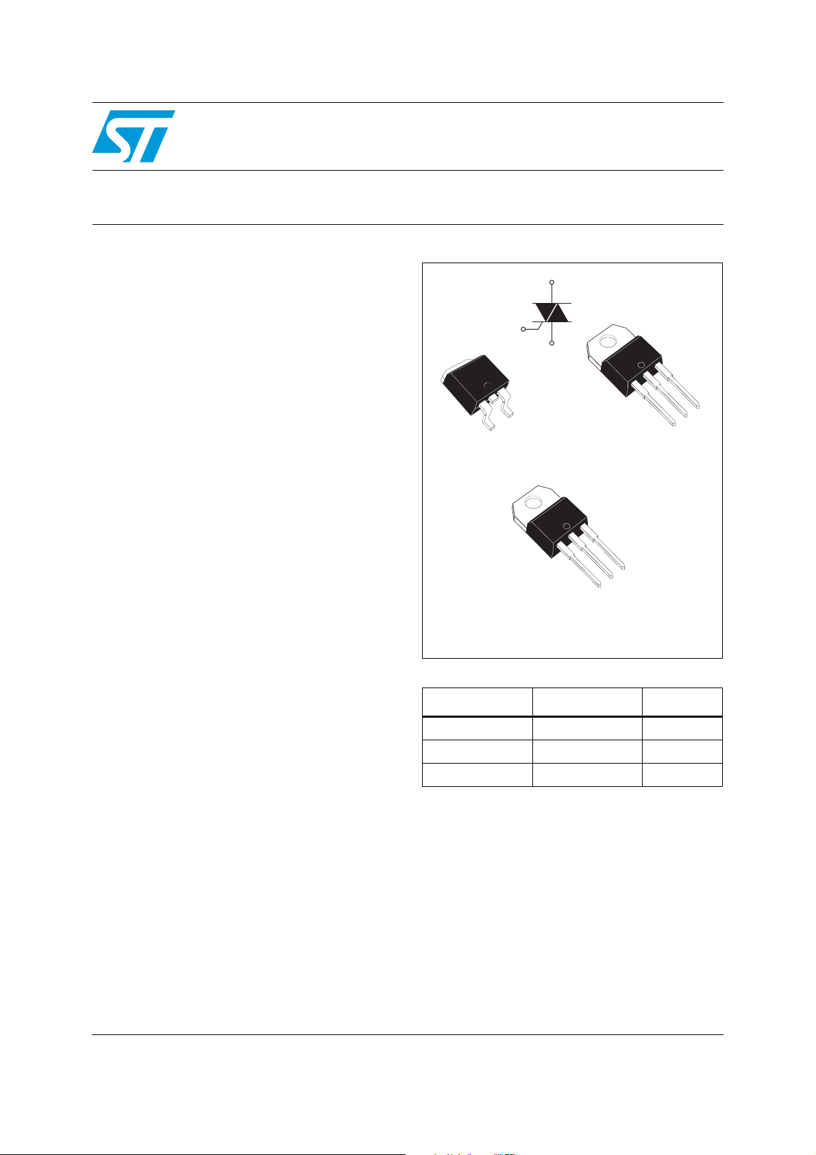
A2
G
A2
G
A2
A1
A2
A1
D2PAK
T12xxH-6G
A2
A1
TO-220AB Insulated
T12xxH-6I
Table 1. Device summary
Symbol Value Unit
I
T(RMS)
V
DRM/VRRM
I
GT
12 A
600 V
35 or 50 mA
A1
TO-220AB
T12xxH-6T
G
G
A2
TM: Snubberless is a trademark of STMicroelectronics
September 2011 Doc ID 13574 Rev 2 1/10
www.st.com
10

Characteristics T1235H, T1250H
1 Characteristics
Table 2. Absolute maximum ratings
Symbol Parameter Value Unit
2
D
I
T(RMS)
I
TSM
²
tI
I
dI/dt
V
DSM/VRSM
I
GM
P
G(AV)
T
stg
T
Table 3. Electrical characteristics (Tj = 25 °C, unless otherwise specified)
On-state rms current (full sine wave)
Non repetitive surge peak on-state
current (full cycle, Tj initial = 25 °C)
²
t Value for fusing tp = 10 ms 95 A2s
Critical rate of rise of on-state current
= 2 x IGT , tr ≤ 100 ns
I
G
Non repetitive surge peak off-state
voltage
Peak gate current tp = 20 µs Tj = 150 °C 4 A
Average gate power dissipation Tj = 150 °C 1 W
Storage junction temperature range
Operating junction temperature range
j
PAK, TO-220AB Tc = 130 °C
12 A
TO-220AB Ins T
= 120 °C
c
F = 50 Hz t = 20 ms 120
F = 60 Hz t = 16.7 ms 126
F = 120 Hz T
= 10 ms Tj = 25 °C
t
p
= 150 °C 50 A/µs
j
V
DRM/VRRM
+ 100
- 40 to + 150
- 40 to + 150
Value
Symbol Test conditions Quadrant
T1235H T1250H
(1)
I
GT
V
GT
V
GD
(2)
I
H
I
L
dV/dt
(dI/dt)c
1. minimum IGT is guaranted at 20% of IGT max.
2. for both polarities of A2 referenced to A1.
VD = 12 V, RL = 33 Ω
VD = V
, RL = 3.3 kΩ I - II - III MIN. 0.15 V
DRM
IT = 500 mA MAX. 35 75 mA
IG = 1.2 I
(2)
VD = 67% V
(2)
Without snubber, Tj = 150 °C MIN. 16 21 A/ms
GT
gate open, Tj = 150 °C MIN. 1000 1500 V/µs
DRM,
I - II - III MAX. 35 50 mA
I - II - III MAX. 1.0 V
I - III
50 90
MAX.
II 80 110
A
V
°C
Unit
mA
2/10 Doc ID 13574 Rev 2

T1235H, T1250H Characteristics
Table 4. Static characteristics
Symbol Test conditions Value Unit
(1)
V
T
V
t0
R
d
ITM = 17 A, tp = 380 µs Tj = 25 °C MAX. 1.5 V
(1)
Threshold voltage Tj = 150 °C MAX. 0.80 V
(1)
Dynamic resistance Tj = 150 °C MAX. 30 mΩ
Tj = 25 °C MAX. 5 µA
V
= V
V
DRM
D/VR
D/VR
I
DRM
(2)
I
RRM
1. for both polarities of A2 referenced to A1
= 380 µs
2. t
p
Table 5. Thermal resistance
RRM
= 150 °C MAX. 3.9
T
j
= 400 V (at peak mains voltage) Tj = 150 °C MAX. 3.2
= 200 V (at peak mains voltage) Tj = 150 °C MAX. 2.7
Symbol Parameter Value Unit
2
D
R
R
th(j-c)
th(j-a)
Junction to case (AC)
Junction to ambient
S = 1 cm
2
PAK / TO-220AB 1.4
TO-220AB Ins 3.3
D2PA K 4 5
TO-220AB / TO-220AB Ins 60
mAV
°C/W
Doc ID 13574 Rev 2 3/10
 Loading...