


Dual low power asynchronous stereo audio Codec
Features
■ Dual 20 bit audio resolution, 8kHz to 96kHz
independent rate ADC and DAC
■ Dual I
■ Sustain complex voice and audio flow with or
■ I
■ Asynchronous sampling ADC and DAC: they
■ Wide master clock range: from 4MHz to 32MHz
■ Stereo headphones drivers, handsfree
■ Mixable analog line inputs
■ Voice filters: 8/16kHz with voice channel filters
■ Automatic gain control for microphone and line-
■ Frequency programmab le cl oc k outp uts
■ Multibit Σ∆ modulators with data weighted
■ DSP functions for bass-treble-volume control,
■ 93 dB dynamic range ADC, 0.001% THD with
■ 95 dB dynamic range DAC, 0.02% THD
2
S or PCM digital interfaces for dual
master
without mixing
2
C/SPI compatible control I/F
do not require oversampled clock and
information on the audio data sampling
frequency (fs). Jitter tolerant fs
loudspeaker driver, line out drivers
in inputs
averaging ADC and DAC
mute, mono/stereo selection, voice channel
filters, de-emphasis filter and dynamic
compression
full scale output @ 2.7V
performance @ 2.7V over 16Ω load
STw5098
with integrated power amplifiers
STw5098
LFBGA 6x6x1.4 (112 pins)
VFBGA 5x5x1 (112 pins)
Description
STw5098 is a dual low power asynchronous
stereo audio CODEC device with headphones
amplifiers for high quality audio listening and
recording.
Two I2S/PCM digital interfaces are available, one
per master for example Bluetooth and Application
Processor, enabling concurrent audio and voice
flow between Network and user.
The STw5098 control registers are accessible
through a selectable I
compatible interface.
2
C-bus compatible or SPI
Applications
■ Digital cellular telephones with application
processor such as mp3 or gaming and
Bluetooth concurrent application
April 2007 Rev 1 1/85
www.st.com
1

Contents STw5098
Contents
1 Overview . . . . . . . . . . . . . . . . . . . . . . . . . . . . . . . . . . . . . . . . . . . . . . . . . . 8
2 Pinout . . . . . . . . . . . . . . . . . . . . . . . . . . . . . . . . . . . . . . . . . . . . . . . . . . . . . 9
3 Block diagram . . . . . . . . . . . . . . . . . . . . . . . . . . . . . . . . . . . . . . . . . . . . . 16
4 Functional description . . . . . . . . . . . . . . . . . . . . . . . . . . . . . . . . . . . . . . 17
4.1 Naming convention . . . . . . . . . . . . . . . . . . . . . . . . . . . . . . . . . . . . . . . . . . 17
4.2 Power supply . . . . . . . . . . . . . . . . . . . . . . . . . . . . . . . . . . . . . . . . . . . . . . 17
4.3 Device programming . . . . . . . . . . . . . . . . . . . . . . . . . . . . . . . . . . . . . . . . 18
4.4 Power up . . . . . . . . . . . . . . . . . . . . . . . . . . . . . . . . . . . . . . . . . . . . . . . . . 19
4.5 Master clock . . . . . . . . . . . . . . . . . . . . . . . . . . . . . . . . . . . . . . . . . . . . . . . 19
4.6 Data rates . . . . . . . . . . . . . . . . . . . . . . . . . . . . . . . . . . . . . . . . . . . . . . . . . 20
4.7 Cloc k generators and master mode function . . . . . . . . . . . . . . . . . . . . . . 20
4.8 Audio digital interfaces . . . . . . . . . . . . . . . . . . . . . . . . . . . . . . . . . . . . . . . 21
4.9 Analog inputs . . . . . . . . . . . . . . . . . . . . . . . . . . . . . . . . . . . . . . . . . . . . . . 22
4.10 Analog output drivers . . . . . . . . . . . . . . . . . . . . . . . . . . . . . . . . . . . . . . . . 23
4.11 Analog mixers . . . . . . . . . . . . . . . . . . . . . . . . . . . . . . . . . . . . . . . . . . . . . . 24
4.12 AD paths . . . . . . . . . . . . . . . . . . . . . . . . . . . . . . . . . . . . . . . . . . . . . . . . . 24
4.13 DA paths . . . . . . . . . . . . . . . . . . . . . . . . . . . . . . . . . . . . . . . . . . . . . . . . . . 25
4.14 Analog-only operations . . . . . . . . . . . . . . . . . . . . . . . . . . . . . . . . . . . . . . . 25
4.15 Automatic Gain Control (AGC) . . . . . . . . . . . . . . . . . . . . . . . . . . . . . . . . . 25
4.16 Inte rrupt request: IRQ pins . . . . . . . . . . . . . . . . . . . . . . . . . . . . . . . . . . . . 26
4.17 Headset plug-in and push-button detection . . . . . . . . . . . . . . . . . . . . . . . 26
4.18 Microphone biasing circuits . . . . . . . . . . . . . . . . . . . . . . . . . . . . . . . . . . . 27
5 Control registers . . . . . . . . . . . . . . . . . . . . . . . . . . . . . . . . . . . . . . . . . . . 28
5.1 Summary . . . . . . . . . . . . . . . . . . . . . . . . . . . . . . . . . . . . . . . . . . . . . . . . . 28
5.2 Supply and power control . . . . . . . . . . . . . . . . . . . . . . . . . . . . . . . . . . . . 30
5.3 Gains . . . . . . . . . . . . . . . . . . . . . . . . . . . . . . . . . . . . . . . . . . . . . . . . . . . . 32
5.4 DSP control . . . . . . . . . . . . . . . . . . . . . . . . . . . . . . . . . . . . . . . . . . . . . . . 36
5.5 Analog functions . . . . . . . . . . . . . . . . . . . . . . . . . . . . . . . . . . . . . . . . . . . . 39
2/85

STw5098 Contents
5.6 Digital audio interfaces master mode and clock generators . . . . . . . . . . . 41
5.7 Digital audio interfaces . . . . . . . . . . . . . . . . . . . . . . . . . . . . . . . . . . . . . . . 43
5.8 Digital filters, software reset and master clock control . . . . . . . . . . . . . . . 45
5.9 Interrupt control and control interface SPI out mode . . . . . . . . . . . . . . . . 46
5.10 AGC . . . . . . . . . . . . . . . . . . . . . . . . . . . . . . . . . . . . . . . . . . . . . . . . . . . . . 48
6 Control interface and master clock . . . . . . . . . . . . . . . . . . . . . . . . . . . . 50
6.1 Control i n terface I2C mode . . . . . . . . . . . . . . . . . . . . . . . . . . . . . . . . . . . 50
6.2 Control i n terface SPI mode . . . . . . . . . . . . . . . . . . . . . . . . . . . . . . . . . . . 51
6.3 Master clock timing . . . . . . . . . . . . . . . . . . . . . . . . . . . . . . . . . . . . . . . . . . 53
7 Audio interfaces . . . . . . . . . . . . . . . . . . . . . . . . . . . . . . . . . . . . . . . . . . . 54
8 Timing specifications . . . . . . . . . . . . . . . . . . . . . . . . . . . . . . . . . . . . . . . 58
9 Operative ranges . . . . . . . . . . . . . . . . . . . . . . . . . . . . . . . . . . . . . . . . . . . 59
9.1 Absolute maximum ratings . . . . . . . . . . . . . . . . . . . . . . . . . . . . . . . . . . . . 59
9.2 Operati ve supply voltage . . . . . . . . . . . . . . . . . . . . . . . . . . . . . . . . . . . . . 59
9.3 Power dissipation . . . . . . . . . . . . . . . . . . . . . . . . . . . . . . . . . . . . . . . . . . . 60
9.4 Typical power dissipation by entity . . . . . . . . . . . . . . . . . . . . . . . . . . . . . . 60
10 Electrical characteristics . . . . . . . . . . . . . . . . . . . . . . . . . . . . . . . . . . . . 62
10.1 Digital interfaces . . . . . . . . . . . . . . . . . . . . . . . . . . . . . . . . . . . . . . . . . . . . 62
10.2 AMCK with sin usoid input . . . . . . . . . . . . . . . . . . . . . . . . . . . . . . . . . . . . . 62
10.3 Analog interfaces . . . . . . . . . . . . . . . . . . . . . . . . . . . . . . . . . . . . . . . . . . . 63
10.4 Headset plug-in and push-button detector . . . . . . . . . . . . . . . . . . . . . . . . 64
10.5 Micr ophone bias . . . . . . . . . . . . . . . . . . . . . . . . . . . . . . . . . . . . . . . . . . . . 64
10.6 Power supply rejection ratio . . . . . . . . . . . . . . . . . . . . . . . . . . . . . . . . . . . 64
10.7 LS and EAR gain limite r . . . . . . . . . . . . . . . . . . . . . . . . . . . . . . . . . . . . . . 65
11 Analog input/output operative ranges . . . . . . . . . . . . . . . . . . . . . . . . . 66
11.1 Analog levels . . . . . . . . . . . . . . . . . . . . . . . . . . . . . . . . . . . . . . . . . . . . . . 66
11.2 Micr ophone input levels . . . . . . . . . . . . . . . . . . . . . . . . . . . . . . . . . . . . . . 66
11.3 Line output levels . . . . . . . . . . . . . . . . . . . . . . . . . . . . . . . . . . . . . . . . . . . 67
11.4 Power output levels HP . . . . . . . . . . . . . . . . . . . . . . . . . . . . . . . . . . . . . . 67
3/85

Contents STw5098
11.5 Power output levels LS and EAR . . . . . . . . . . . . . . . . . . . . . . . . . . . . . . . 67
12 Stereo audio ADC specifications . . . . . . . . . . . . . . . . . . . . . . . . . . . . . . 69
13 Stereo audio DAC specifications . . . . . . . . . . . . . . . . . . . . . . . . . . . . . . 70
14 AD to DA mixing (sidetone) specifications . . . . . . . . . . . . . . . . . . . . . . 71
15 Stereo analog-only path specifications . . . . . . . . . . . . . . . . . . . . . . . . 72
16 ADC (TX) & DAC (RX) specifications with voice filters selected . . . . . 73
17 Typical performance plots . . . . . . . . . . . . . . . . . . . . . . . . . . . . . . . . . . . 74
18 Package mechanical data . . . . . . . . . . . . . . . . . . . . . . . . . . . . . . . . . . . . 77
18.1 LFBGA 6x6x1.4 . . . . . . . . . . . . . . . . . . . . . . . . . . . . . . . . . . . . . . . . . . . . 78
18.2 VFBGA 5x5x1.0 . . . . . . . . . . . . . . . . . . . . . . . . . . . . . . . . . . . . . . . . . . . . 80
19 Application schematics . . . . . . . . . . . . . . . . . . . . . . . . . . . . . . . . . . . . . 82
20 Ordering information . . . . . . . . . . . . . . . . . . . . . . . . . . . . . . . . . . . . . . . 84
21 Revision history . . . . . . . . . . . . . . . . . . . . . . . . . . . . . . . . . . . . . . . . . . . 84
4/85

STw5098 List of tables
List of tables
Table 1. STw5098 pin description . . . . . . . . . . . . . . . . . . . . . . . . . . . . . . . . . . . . . . . . . . . . . . . . . . 10
Table 2. Control register summary . . . . . . . . . . . . . . . . . . . . . . . . . . . . . . . . . . . . . . . . . . . . . . . . . . 28
Table 3. CR0 description . . . . . . . . . . . . . . . . . . . . . . . . . . . . . . . . . . . . . . . . . . . . . . . . . . . . . . . . . 30
Table 4. CR1 description . . . . . . . . . . . . . . . . . . . . . . . . . . . . . . . . . . . . . . . . . . . . . . . . . . . . . . . . . 31
Table 5. CR2 description . . . . . . . . . . . . . . . . . . . . . . . . . . . . . . . . . . . . . . . . . . . . . . . . . . . . . . . . . 31
Table 6. CR3 and CR4 description. . . . . . . . . . . . . . . . . . . . . . . . . . . . . . . . . . . . . . . . . . . . . . . . . . 32
Table 7. CR5 and CR6 description. . . . . . . . . . . . . . . . . . . . . . . . . . . . . . . . . . . . . . . . . . . . . . . . . . 33
Table 8. CR7 description . . . . . . . . . . . . . . . . . . . . . . . . . . . . . . . . . . . . . . . . . . . . . . . . . . . . . . . . . 33
Table 9. CR8 and CR9 description. . . . . . . . . . . . . . . . . . . . . . . . . . . . . . . . . . . . . . . . . . . . . . . . . . 33
Table 10. CR10 and CR11 description. . . . . . . . . . . . . . . . . . . . . . . . . . . . . . . . . . . . . . . . . . . . . . . . 34
Table 11. CR12 and CR13 description. . . . . . . . . . . . . . . . . . . . . . . . . . . . . . . . . . . . . . . . . . . . . . . . 35
Table 12. CR14 description . . . . . . . . . . . . . . . . . . . . . . . . . . . . . . . . . . . . . . . . . . . . . . . . . . . . . . . . 36
Table 13. CR15 description . . . . . . . . . . . . . . . . . . . . . . . . . . . . . . . . . . . . . . . . . . . . . . . . . . . . . . . . 37
Table 14. CR16 description . . . . . . . . . . . . . . . . . . . . . . . . . . . . . . . . . . . . . . . . . . . . . . . . . . . . . . . . 38
Table 15. CR17 description . . . . . . . . . . . . . . . . . . . . . . . . . . . . . . . . . . . . . . . . . . . . . . . . . . . . . . . . 39
Table 16. CR18 description . . . . . . . . . . . . . . . . . . . . . . . . . . . . . . . . . . . . . . . . . . . . . . . . . . . . . . . . 39
Table 17. CR19 description . . . . . . . . . . . . . . . . . . . . . . . . . . . . . . . . . . . . . . . . . . . . . . . . . . . . . . . . 40
Table 18. CR21-20 and CR24-23 description. . . . . . . . . . . . . . . . . . . . . . . . . . . . . . . . . . . . . . . . . . . 41
Table 19. CR22 and CR25 description. . . . . . . . . . . . . . . . . . . . . . . . . . . . . . . . . . . . . . . . . . . . . . . . 41
Table 20. CR26 description . . . . . . . . . . . . . . . . . . . . . . . . . . . . . . . . . . . . . . . . . . . . . . . . . . . . . . . . 43
Table 21. CR27 description . . . . . . . . . . . . . . . . . . . . . . . . . . . . . . . . . . . . . . . . . . . . . . . . . . . . . . . . 43
Table 22. CR28 description . . . . . . . . . . . . . . . . . . . . . . . . . . . . . . . . . . . . . . . . . . . . . . . . . . . . . . . . 44
Table 23. CR29 description . . . . . . . . . . . . . . . . . . . . . . . . . . . . . . . . . . . . . . . . . . . . . . . . . . . . . . . . 45
Table 24. CR30 description . . . . . . . . . . . . . . . . . . . . . . . . . . . . . . . . . . . . . . . . . . . . . . . . . . . . . . . . 45
Table 25. CR31 description . . . . . . . . . . . . . . . . . . . . . . . . . . . . . . . . . . . . . . . . . . . . . . . . . . . . . . . . 46
Table 26. CR32 description . . . . . . . . . . . . . . . . . . . . . . . . . . . . . . . . . . . . . . . . . . . . . . . . . . . . . . . . 46
Table 27. CR33 description . . . . . . . . . . . . . . . . . . . . . . . . . . . . . . . . . . . . . . . . . . . . . . . . . . . . . . . . 47
Table 28. CR 34 description . . . . . . . . . . . . . . . . . . . . . . . . . . . . . . . . . . . . . . . . . . . . . . . . . . . . . . . . 48
Table 29. CR 35 description . . . . . . . . . . . . . . . . . . . . . . . . . . . . . . . . . . . . . . . . . . . . . . . . . . . . . . . . 49
Table 30. Control interface timing with I²C format . . . . . . . . . . . . . . . . . . . . . . . . . . . . . . . . . . . . . . . 51
Table 31. Control interface signal timing with SPI format. . . . . . . . . . . . . . . . . . . . . . . . . . . . . . . . . . 52
Table 32. AMCK timing. . . . . . . . . . . . . . . . . . . . . . . . . . . . . . . . . . . . . . . . . . . . . . . . . . . . . . . . . . . . 53
Table 33. Audio interface signal timings. . . . . . . . . . . . . . . . . . . . . . . . . . . . . . . . . . . . . . . . . . . . . . . 57
Table 34. Absolute maximum ratings . . . . . . . . . . . . . . . . . . . . . . . . . . . . . . . . . . . . . . . . . . . . . . . . . 59
Table 35. Operative supply voltage . . . . . . . . . . . . . . . . . . . . . . . . . . . . . . . . . . . . . . . . . . . . . . . . . . 59
Table 36. Power dissipation . . . . . . . . . . . . . . . . . . . . . . . . . . . . . . . . . . . . . . . . . . . . . . . . . . . . . . . . 60
Table 37. Typical power dissipation, no master clock . . . . . . . . . . . . . . . . . . . . . . . . . . . . . . . . . . . . 60
Table 38. Typical power dissipation with master clock AMCK = 13 MHz . . . . . . . . . . . . . . . . . . . . . . 61
Table 39. Digital interfaces specifications. . . . . . . . . . . . . . . . . . . . . . . . . . . . . . . . . . . . . . . . . . . . . . 62
Table 40. AMCK with sinusoid input specifications . . . . . . . . . . . . . . . . . . . . . . . . . . . . . . . . . . . . . . 62
Table 41. Analog interface specifications . . . . . . . . . . . . . . . . . . . . . . . . . . . . . . . . . . . . . . . . . . . . . . 63
Table 42. Headset plug-in and push-button detector specifications. . . . . . . . . . . . . . . . . . . . . . . . . . 64
Table 43. Microphone bias specifications. . . . . . . . . . . . . . . . . . . . . . . . . . . . . . . . . . . . . . . . . . . . . . 64
Table 44. Power supply rejection ratio specifications . . . . . . . . . . . . . . . . . . . . . . . . . . . . . . . . . . . . . 64
Table 45. LS and EAR gain limiter . . . . . . . . . . . . . . . . . . . . . . . . . . . . . . . . . . . . . . . . . . . . . . . . . . . 65
Table 46. Reference full scale analog levels . . . . . . . . . . . . . . . . . . . . . . . . . . . . . . . . . . . . . . . . . . . 66
Table 47. Microphone input levels, absolute levels at pins connected to preamplifiers . . . . . . . . . . . 66
Table 48. Microphone input levels, absolute levels at pins connected to the line-in amplifiers . . . . . 66
5/85

List of tables STw5098
Table 49. Absolute levels at OLP/OLN, ORP/ORN . . . . . . . . . . . . . . . . . . . . . . . . . . . . . . . . . . . . . . 67
Table 50. Absolute levels at HPL - HPR. . . . . . . . . . . . . . . . . . . . . . . . . . . . . . . . . . . . . . . . . . . . . . . 67
Table 51. Absolute levels at 1EARP-1EARN and 2LSP - 2LSN. . . . . . . . . . . . . . . . . . . . . . . . . . . . . 68
Table 52. Stereo audio ADC specifications . . . . . . . . . . . . . . . . . . . . . . . . . . . . . . . . . . . . . . . . . . . . 69
Table 53. Stereo audio DAC specifications . . . . . . . . . . . . . . . . . . . . . . . . . . . . . . . . . . . . . . . . . . . . 70
Table 54. AD to DA mixing (sidetone) specifications . . . . . . . . . . . . . . . . . . . . . . . . . . . . . . . . . . . . . 71
Table 55. Stereo analog-only path specifications . . . . . . . . . . . . . . . . . . . . . . . . . . . . . . . . . . . . . . . . 72
Table 56. ADC (TX) & DAC (RX) specifications with voice filters selected. . . . . . . . . . . . . . . . . . . . . 73
Table 57. Dimensions of LFBGA 6x6x1.4 112 4R11x11. 0.5 . . . . . . . . . . . . . . . . . . . . . . . . . . . . . . . 78
Table 58. Dimensions of VFBGA 5x5x1.0 112 balls 0.4 mm pitch . . . . . . . . . . . . . . . . . . . . . . . . . . . 80
Table 59. Order codes . . . . . . . . . . . . . . . . . . . . . . . . . . . . . . . . . . . . . . . . . . . . . . . . . . . . . . . . . . . . 84
Table 60. Document revision history . . . . . . . . . . . . . . . . . . . . . . . . . . . . . . . . . . . . . . . . . . . . . . . . . 84
6/85

STw5098 List of figures
List of figures
Figure 1. Pin assignment . . . . . . . . . . . . . . . . . . . . . . . . . . . . . . . . . . . . . . . . . . . . . . . . . . . . . . . . . . . 9
Figure 2. STw5098 block diagram . . . . . . . . . . . . . . . . . . . . . . . . . . . . . . . . . . . . . . . . . . . . . . . . . . . 16
Figure 3. Power up block diagram: example shown for one entity . . . . . . . . . . . . . . . . . . . . . . . . . . 19
Figure 4. Plug-in and push-button detection application note . . . . . . . . . . . . . . . . . . . . . . . . . . . . . . 26
Figure 5. Control interface I2C format . . . . . . . . . . . . . . . . . . . . . . . . . . . . . . . . . . . . . . . . . . . . . . . . 50
Figure 6. Control interface: I2C format timing . . . . . . . . . . . . . . . . . . . . . . . . . . . . . . . . . . . . . . . . . . 50
Figure 7. Control interface SPI format . . . . . . . . . . . . . . . . . . . . . . . . . . . . . . . . . . . . . . . . . . . . . . . . 51
Figure 8. Control interface: SPI format timing . . . . . . . . . . . . . . . . . . . . . . . . . . . . . . . . . . . . . . . . . . 52
Figure 9. Audio interfaces formats: delayed, left and right justified . . . . . . . . . . . . . . . . . . . . . . . . . . 54
Figure 10. Audio interfaces formats: DSP, SPI and PCM . . . . . . . . . . . . . . . . . . . . . . . . . . . . . . . . . . 55
Figure 11. Audio interface timings: master mode . . . . . . . . . . . . . . . . . . . . . . . . . . . . . . . . . . . . . . . . 56
Figure 12. Audio interface timing: slave mode. . . . . . . . . . . . . . . . . . . . . . . . . . . . . . . . . . . . . . . . . . . 56
Figure 13. A.C. testing input-output waveform. . . . . . . . . . . . . . . . . . . . . . . . . . . . . . . . . . . . . . . . . . . 58
Figure 14. Bass treble control, de-emphasis filter . . . . . . . . . . . . . . . . . . . . . . . . . . . . . . . . . . . . . . . . 74
Figure 15. Dynamic compressor transfer function . . . . . . . . . . . . . . . . . . . . . . . . . . . . . . . . . . . . . . . . 74
Figure 16. ADC audio path measured filter response . . . . . . . . . . . . . . . . . . . . . . . . . . . . . . . . . . . . . 74
Figure 17. ADC in band audio path measured filter response. . . . . . . . . . . . . . . . . . . . . . . . . . . . . . . 74
Figure 18. DAC digital audio filter characteristics . . . . . . . . . . . . . . . . . . . . . . . . . . . . . . . . . . . . . . . . 74
Figure 19. DAC in band digital audio filter characteristics . . . . . . . . . . . . . . . . . . . . . . . . . . . . . . . . . . 74
Figure 20. ADC 96 kHz audio path measured filter response . . . . . . . . . . . . . . . . . . . . . . . . . . . . . . . 75
Figure 21. ADC 96 kHz audio in-band measured filter response. . . . . . . . . . . . . . . . . . . . . . . . . . . . . 75
Figure 22. ADC voice TX path measured filter response. . . . . . . . . . . . . . . . . . . . . . . . . . . . . . . . . . . 75
Figure 23. ADC voice TX path measured in-band filter response . . . . . . . . . . . . . . . . . . . . . . . . . . . . 75
Figure 24. DAC voice (RX) digital filter characteristics . . . . . . . . . . . . . . . . . . . . . . . . . . . . . . . . . . . . 75
Figure 25. DAC voice (RX) in-band digital filter characteristics . . . . . . . . . . . . . . . . . . . . . . . . . . . . . . 75
Figure 26. ADC path FFT. . . . . . . . . . . . . . . . . . . . . . . . . . . . . . . . . . . . . . . . . . . . . . . . . . . . . . . . . . . 76
Figure 27. ADC S/N versus input-level . . . . . . . . . . . . . . . . . . . . . . . . . . . . . . . . . . . . . . . . . . . . . . . . 76
Figure 28. DAC path FFT. . . . . . . . . . . . . . . . . . . . . . . . . . . . . . . . . . . . . . . . . . . . . . . . . . . . . . . . . . . 76
Figure 29. DAC S/N versus input-level . . . . . . . . . . . . . . . . . . . . . . . . . . . . . . . . . . . . . . . . . . . . . . . . 76
Figure 30. Analog path FFT. . . . . . . . . . . . . . . . . . . . . . . . . . . . . . . . . . . . . . . . . . . . . . . . . . . . . . . . . 76
Figure 31. Analog path S/N versus input-level. . . . . . . . . . . . . . . . . . . . . . . . . . . . . . . . . . . . . . . . . . . 76
Figure 32. LFBGA 6x6x1.4 112 4R11x11 0.5 drawing . . . . . . . . . . . . . . . . . . . . . . . . . . . . . . . . . . . . 79
Figure 33. VFBGA 5x5x1.0 112 0.4 drawing . . . . . . . . . . . . . . . . . . . . . . . . . . . . . . . . . . . . . . . . . . . . 81
Figure 34. STw5098 application schematics . . . . . . . . . . . . . . . . . . . . . . . . . . . . . . . . . . . . . . . . . . . . 83
7/85

Overview STw5098
1 Overview
● Dual 20 bit audio resolution, 8kHz to 96kHz independent rate ADC and DAC
● Dual I
● Sustain complex voice and audio flow with or without mixing
● Two I
● Asynchronous sampling ADC and DAC that do not require oversampled clock and
● Wide master clock range from 4MHz to 32MHz
● Two stereo headphones drivers, hand free loudspeaker driver, line out drivers
● Mixable analog line inputs
● Voice filters: 8/16kHz with voice channel filters
● Automatic gain control for microphone and line-in inputs
● Four programmable master/slave serial audio data interfaces: I
● Frequency programmable clock outputs
● Multibit Σ∆ modulators with data weighted averaging ADC and DAC
● Four DSP functions for bass-treble-volume control, mute, mono/stereo selection, voice
● 93 dB dynamic range ADC, 0.001% THD with full scale with full scale output @ 2.7V
● 95 dB dynamic range DAC, 0.02% THD performance @ 2.7V over 16Ω load
2
S/PCM digital interfaces for dual master
2
C/SPI compatible independent control interfaces
information on the audio data sampling frequency (fs). Jitter tolerant fs
2
S, SPI, PCM
compatible and other formats
channel filters, de-emphasis filter and dynamic compression
Analog inputs
● Selectable stereo differential or single-ended microphone amplifier inputs with 51dB
range programmable gain
● 2 microphone biasing output
● Microphone plug-in and push-button detection input
● Selectable stereo differential or single-ended line inputs with 38dB range
programmable gain
Analog output drivers
● 2 Stereo headphones outputs. driving capability: 40mW (0.1% THD) over 16Ω with
40dB range programmable gain
● Common mode voltage headphones driver (phantom ground)
● 1 Balanced loudspeaker output with driving capability up to 500mW (V
THD) over 8Ω with 30dB range programmable gain
● 1 Balanced earphone output with driving capability up to 125mW
● Transient suppression filter during power up and power down
● Balanced/unbalanced stereo line outputs with 1 kΩ driving capability
CCLS
>3.5V; 1%
8/85

STw5098 Pinout
2 Pinout
Figure 1. Pin assignment
1234567891011
GND
1SCLK
1AD_OCK
2SDA/SDIN
1DA_OCK
1AD_CK 2AS/CSB 2AD_DATA
2AD_SYNC
1DA_SYNC
1DA_DATA
A
2SCLK
2AD_OCK
1CMOD
2DA_OCK
2DA_CK
AMCK
VCC 2DA_SYNC
2DA_DATA2HDET
GND
B
VCCA
1HDET
VCCA
2CMOD
1SDA/SDIN 2AD_CK
1AD_DATA
1AD_SYNC
2IRQ
2MBIAS
1MBIAS
C
1MICLN1AUX1L2AUX1L
VCC
VCCIO
1DA_CK
1AS/CSB
1IRQ
VCCA 2AUX1R
1AUX1R
D
1MICLP
2MICLN1AUX3L2AUX3L
2CAPLINEIN 2AUX3R
1MICRN 2MICRN
E
2CAPMIC
1CAPMIC GNDA
2MICLP
1CAPLINEIN 2MICRP
1MICRP 1AUX3R
F
1AUX2LN 2LINEINL2AUX2LN
1LINEINL
1AUX2RPGNDA
2AUX2RN1AUX2RN
G
1AUX2LP 2AUX2LP
2OLN
GNDCM
1EARPS
1EARP
VCCP
1HPR
2ORN
2LINEINR
2AUX2RP
H
1OLN
1OLP
2OLP
2HPL
1VCMHP
1CAPEAR
1EARN
VCCLS
2ORP
1ORN
1LINEINR
J
GNDCM VCCP
1HPL
2VCMHPS VCCLS
GNDP
GNDP
1EARNS
VCCLS
1ORP
GNDP
K
VCCP
GNDP 1VCMHPS
2VCMHP
2LSPS 2LSP
2CAPLS
2LSN
2LSNS
VCCP 2HPR
L
9/85

Pinout STw5098
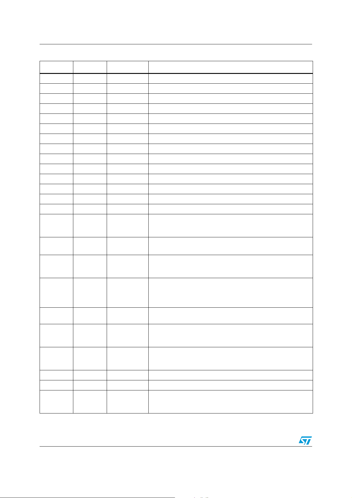
Table 1. STw5098 pin description
Position Type Pin name Description
A1 P GND Ground pin for the digital section
A2 DI 1SCLK Control interface serial clock input
A3 DO 1AD_OCK Oversampled clock out from AD clock generator
2
A4 DIOD 2SDA/SDIN
Control interface serial data input-output in I
interface serial data input in SPI mode (SDIN).
A5 DO 1DA_OCK Oversampled clock out from DA clock generator
A6 DIO 1AD_CK Serial data clock for stereo A/D converter
2
C mode (AS).
A7 DI 2AS/CSB
Control interface address select in I
Interface enable signal in SPI mode (CSB).
A8 DO 2AD_DATA Serial data out for stereo A/D converter
A9 DIO 2AD_SYNC Frame sync for stereo A/D converter
A10 DIO 1DA_SYNC Frame sync for stereo D/A converter
A11 DI 1DA_DATA Serial data In for stereo D/A converter
B1 AI 2HDET
Headset detection input
(microphone plug-in and push-button detection)
C mode (SDA), control
B2 DI 2SCLK Control interface serial clock input
B3 DO 2AD_OCK Oversampled clock out from AD clock generator
B4 DI 1CMOD Control interface type selector I
2
C-bus mode or SPI mode
B5 DO 2DA_OCK Oversampled clock out from DA clock generator
B6 DIO 2DA_CK Serial data clock for stereo D/A converter
Master clock input. Accepted range 4 MHz to 32 MHz.
B7 DI
AI
B8 P VCC
AMCK
AMCK is a digital square wave
AMCK is an analog sinewave (
Section 10.2 on page 62
Power supply pin for the digital section.
Operating range: from 1.71 V to 2.7 V
B9 DIO 2DA_SYNC Frame sync for stereo D/A converter
B10 DI 2DA_DATA Serial data in for stereo D/A converter
B11 P GND Ground pin for the digital section
Power supply pin for the analog section.
C1 P VCCA
Standard operating range: from 2.7V to 3.3V
Low voltage (LV) range: from 2.4V to 2.7V
C2 AI 1HDET
Headset detection input
(microphone plug-in and push-button detection)
Power supply pin for the analog section.
C3 P VCCA
Standard operating range: from 2.7V to 3.3V
Low voltage (LV) range: from 2.4V to 2.7V
C4 DI 2CMOD Control interface type selector I
2
C-bus mode or SPI mode.
)
10/85

STw5098 Pinout
Table 1. STw5098 pin description
Position Type Pin name Description
2
C5 DIOD 1SDA/SDIN
Control interfac e s erial da ta i npu t-ou tpu t in I
interface serial data input in SPI mode (SDIN).
C6 DIO 2AD_CK Serial data clock for stereo A/D conver ter
C7 DO 1AD_DATA Serial data out for stereo A/D converter
C8 DIO 1AD_SYNC Frame sync for stereo A/D converter
C9 DO 2IRQ Programmable interrupt output. Active low signal.
C10 AO 2MBIAS Microphone biasing pin. Fixed voltage reference
C11 AO 1MBIAS Microphone biasing pin. Fixed voltage reference
D1 AI 2AUX1L Left and right channel single ended pins for microphone or line input
D2 AI 1AUX1L Left and right channel single ended pins for microphone or line input
D3 AI 1MICLN Left and right channel differential pins for microphone input
D4 P VCC
D5 P VCCIO
Power supply pin for the digital section.
Operating range: from 1.71V to 2.7V
Power supply pin for the digital I ⁄ O buffers.
Operating ranges: from 1.2V to 1.8V and from 1.71V to V
D6 DIO 1DA_CK Serial data clock for stereo D/A converter
2
C mode (AS)
D7 DI 1AS/CSB
Control interface address select in I
Interface enable signal in SPI mode (CSB)
C mode (SDA). Control
CC
D8 DO 1IRQ Programmable interrupt output. Active low signal.
Power supply pin for the analog section.
D9 P VCCA
Standard operating range: from 2.7V to 3.3V
Low voltage (LV) range: from 2.4V to 2.7V
D10 AI 1AUX1R Left and right channel single ended pins for microphone or line input
D11 AI 2AUX1R Left and right channel single ended pins for microphone or line input
E1 AI 2AUX3L Left and right channel single ended pins for microphone or line input
E2 AI 1AUX3L Left and right channel single ended pins for microphone or line input
E3 AI 1MICLP Left and right channel differential pins for microphone input
E4 AI 2MICLN Left and right channel differential pins for microphone input
E8 AI 2CAPLINEIN A capacitor must be connected between CAPLINEIN and ground
E9 AI 1MICRN Left and right channel differential pins for microphone input
E10 AI 2AUX3R Left and right channel single ended pins for microphone or line input
E11 AI 2MICRN Left and right channel differential pins for microphone input
F1 AI 2CAPMIC A capacitor must be connected between CAPMIC and ground.
F2 AI 1CAPMIC A capacitor must be connected between CAPMIC and ground
F3 P GNDA Ground pin for the analog section
F4 AI 2MICLP Left and right channel differential pins for microphone input
11/85
Pinout STw5098
Table 1. STw5098 pin description
Position Type Pin name Description
F8 AI 1CAPLINEIN A capacitor must be connected between CAPLINEIN and ground
F9 AI 1MICRP Left and right channel differential pins for microphone input
F10 AI 1AUX3R Left and right channel single ended pins for microphone or line input
F11 AI 2MICRP Left and right channel differential pins for microphone input
G1 AI 1AUX2LN Left and right channel differential pins for microphone or line input
G2 AI 2AUX2LN Left and right channel differential pins for microphone or line input
G3 AI 1LINEINL Left and right channel single ended pins for line input
G4 AI 2LINEINL Left and right channel single ended pins for line input
G8 P GNDA Ground pin for the analog section
G9 AI 1AUX2RP Left and right channel differential pins for microphone or line input.
G10 AI 1AUX2RN Left and right channel differential pins for microphone or line input
G11 AI 2AUX2RN Left and right channel differential pins for microphone or line input
H1 AI 1AUX2LP Left and right channel differential pins for microphone or line input
H2 AI 2AUX2LP Left and right channel differential pins for microphone or line input
Audio differential line out amplifier for left and right channels. This
H3 AO 2OLN
H4 P GNDCM
H5 AO 1EARPS
H6 AO 1EARP
outputs can drive up to 1kΩ resistive load. Can be used as single
ended output.
Ground pin for analog reference.
GNDCM can be connected to GNDA
EARPS, EARNS (sense) pins must be connected on the application
board to EARP, EARN pins respectively. The connection must be as
close as possible to the pins.
Analog differenti al lou ds pea ker amplifier output for left channel or
right channel or the sum of both. This output can drive 50nF (with
series resistor) or directly an earp iece transd uctor from 8 Ω. to 32Ω.
Can deliver from 500mW to 125mW.
H7 P VCCP
H8 AO 1HPR
H9 AO 2ORN
H10 AI 2LINEINR Left and right channel single ended pins for line input
H11 AI 2AUX2RP Left and right channel differential pins for microphone or line input
J1 AO 1OLN
12/85
Power supply pin for the left and right output drivers (headphones
and line-out). Operating range: from V
Audio single ended headphones amplifier outputs for left and right
channels. The outputs can drive 50nF (with series resistor) or
directly an earpiece transductor of 16Ω.
Audio differential line out amplifier for left and right channels. This
outputs can drive up to 1kΩ resistive load. Can be used as single
ended output.
Audio differential line out amplifier for left and right channels. This
outputs can drive up to 1kΩ resistive load. Can be used as single
ended output.
CCA
to 3.3V

STw5098 Pinout
Table 1. STw5098 pin description
Position Type Pin name Description
Audio differential line out amplifier for left and right channels. This
J2 AO 1OLP
J3 AO 2OLP
J4 AO 2HPL
J5 AO 1VCMHP
J6 AI 1CAPEAR A capacitor can be connected between this node and ground
J7 AO 1EARN
J8 P VCCLS
J9 AO 2ORP
outputs can drive up to 1kΩ resistive load. Can be used as single
ended output.
Audio differential line out amplifier for left and right channels. This
outputs can drive up to 1kΩ resistive load. Can be used as single
ended output.
Audio single ended headphones amplifier outputs for left and right
channels. The outputs can drive 50nF (with series resistor) or
directly an earpiece transductor of 16Ω.
Common mode voltage headphones output. The negative pins of
headphones left and right speakers can be connected to this pin to
avoid decoupling capacitors.
Analog differenti al lou ds pea ker amplifier output for Left channel or
Right channel or the sum of both. This output can drive 50nF (with
series resistor) or directly an earp iece transd uctor from 8 Ω to 32Ω.;
It can deliver from 500mW to 125mW.
Power supply pin for the mono differential output driver. Operating
range: from V
CCA
to 5.5V
Audio differential line out amplifier for left and right channels. This
outputs can drive up to 1kΩ resistive load. Can be used as single
ended output.
Audio differential line out amplifier for left and right channels. This
J10 AO 1ORN
outputs can drive up to 1kΩ resistive load. Can be used as single
ended output.
J11 AI 1LINEINR Left and right channel single ended pins for line input
K1 P GNDCM
Ground pin for analog reference.
GNDCM can be connected to GNDA
Power supply pins for the left and right output drivers (headphones
K2 P VCCP
and line-out).
Operating range: from V
CCA
to 3.3V
Audio single ended headphones amplifier outputs for left and right
K3 AO 1HPL
channels. The outputs can drive 50nF (with series resistor) or
directly an earpiece transductor of 16Ω.
VCMHPS (sense) pin m ust b e con necte d on t he app licat ion bo ard to
K4 AO 2VCMHPS
VCMHP pin. The connection must be as close as possible to the
pins.
K5 P VCCLS
K6 P GNDP
K7 P GNDP
Power supply pin for the mono differential output driver. Operating
range: from V
CCA
to 5.5V
Ground pin for the left, right and mono-differential output drivers.
GNDP and GNDA must be connected together.
Ground pin for the left, right and mono-differential output drivers.
GNDP and GNDA must be connected together.
13/85

Pinout STw5098
Table 1. STw5098 pin description
Position Type Pin name Description
EARPS, EARNS (sense) pins must be connected on the application
K8 AO 1EARNS
board to EARP, EARN pins respectively. The connection must be as
close as possible to the pins.
K9 P VCCLS
K10 AO 1ORP
K11 P GNDP
L1 P VCCP
L2 P GNDP
L3 AO 1VCMHPS
L4 AO 2VCMHP
L5 AO 2LSPS
L6 AO 2LSP
Power supply pins for the mono differential output driver. Operating
range: from V
CCA
to 5.5V
Audio differential line out amplifier for left and right channels. This
outputs can drive up to 1kΩ resistive load. Can be used as single
ended output.
Ground pin for the left, right and mono-differential output drivers.
GNDP and GNDA must be connected together.
Power supply pin for the left and right output drivers (headphones
and line-out).
Operating range: from V
CCA
to 3.3V
Ground pin for the left, right and mono-differential output drivers.
GNDP and GNDA must be connected together.
VCMHPS (sense) pin m ust b e con necte d on t he app licat ion bo ard to
VCMHP pin. The connection must be as close as possible to the
pins.
Common mode voltage headphones output. The negative pins of
headphones left and right speakers can be connected to this pin to
avoid decoupling capacitors.
LSPS, LSNS (sense) pins must be connected on the application
board to LSP, LSN pins respectively. The connection must be as
close as possible to the pins.
Analog differenti al lou ds pea ker amplifier output for Left channel or
Right channel or the sum of both. This output can drive 50nF (with
series resistor) o r directly an earpiece transductor of 8Ω.; It can
deliver up to 500mW.
L7 AI 2CAPLS A capacitor can be connected between this node and ground
Analog differenti al lou ds pea ker amplifier output for Left channel or
L8 AO 2LSN
Right channel or the sum of both. This output can drive 50nF (with
series resistor) or direct ly an e arpiece tr an sductor of 8Ω. Can deliver
up to 500mW.
LSPS, LSNS (sense) pins must be connected on the application
L9 AO 2LSNS
board to LSP, LSN pins respectively. The connection must be as
close as possible to the pins.
L10 P VCCP
Power supply pin for the left and right output drivers (headphones
and line-out). Operating range: from V
CCA
to 3.3V
Audio single ended headphones amplifier outputs for left and right
L11 AO 2HPR
channels. The outputs can drive 50nF (with series resistor) or
directly an earpiece transductor of 16Ω.
14/85

STw5098 Pinout
Type definitions
AI - Analog input
AO - Analog output
AIO - Analog input output
DI - Digital input
DO - Digital output
DIO - Digital input output
DIOD - Digital input output open drain
P - Pow er supply or ground
15/85

Block diagram STw5098
3 Block diagram
Figure 2. STw5098 block diagram
2CAPLINEIN
2CAPMIC
2LINEINL
2LINEINR
2AUX3R
2AUX3L
2AUX2NR
2AUX2PR
2AUX2NL
2AUX2PL
2AUX1R
2AUX1L
2MICRN
2MICRP
2MICLN
2MICLP
Diff.
Stereo
LINEIN
LINSEL2
LINLG2
LINRG2
+18 dB Step 2
:
-20
AGC
(from DSP)
2SCLK
2CMOD2AS/CSB1SCLK 2SDA/SDIN1HDET
Control I/F
1AS/CSB
1CMOD
1SDA/SDIN
Diff.
Stereo
Stereo
Sing.E.
AUX1
AUX2
AUX3
MUTE
Amps
LIN L-R
L
R
AGC
(from DSP)
Stereo Path
Registers
Logic
Control
Stereo
Stereo
Sing.E.
Sing.E.
MIC
AUX1
AUX2
AUX3
MUTE
MICSEL2MICLG2
39 dB
÷
Step 1.5
0
PreAmps
MICRG2
MIC L-R
0 dB
÷
MICLA2
Step 1.5
MICRA2
-12
L
R
2MBIAS
2OLP
2OLN
2ORP
2ORN
Mode
Comm.
Left
LineOut
Right
Mic.
Bias
2.1V
Reference
ADMIC2ADLIN2
LineOut
LOG: -18:0 dB Step 3
MICLO2
-40:0 dB Step 2
MIXMIC 2
MIXLIN2
2VCMHP
2VCMHPS
2HPL
HPLG2
Left
Driver
Filter
Suppr.
Transient
RL
2LSPS
2LSP
2CAPLS
2LSN
2HPR
Right
Driver
CM
Driver
Filter
Suppr.
Transient
Voltage
Reference
-40:0 dB Step 2
2LSNS
2AD_SYNC
2AD_CK
2AD_DATA
HPRG2
Mono
Driver
LSG2
6 dB Step 2
:
-24
LSSEL2
Audio
Filter
Suppr.
Transient
L
R
(L+R)/2
Rate
Converter
AD Sample
ADC
Σ∆
Digital
2AD_OCK
AD-I/F
Mode
Master
CK Gen/
AGC
(Mic&Lin)
ADMONO
DSP2
ADC
Gain
Digital
ADCHSW
Filter
Audio/Voice
MIXDAC2
Filter
Analog
2DA_OCK
2DA_SYNC
2DA_CK
2DA_DATA
AMCK
PLL
MCK2
Gain
Mixing
Bass
Treble
DA to AD
(Audio Only)
(Audio only)
Gain
Mixing
AD to DA
(sidetone)
Σ∆
DAC
Modulator
Audio
DA-I/F
Mode
Master
CK Gen/
Dyn.Comp.
DACHSW
DAMONO
DAC
Gain
Digital
Filter
Audio/Voice
Rate
Converter
DA Sample
Digital
DA-PLL
Stereo DAC
AD-PLL
DA_SYNC2
Stereo ADC
AD_SYNC2
Headset
Detection
2IRQ
1IRQ 2HDET
VCCA
VCCIO GNDVCC
GNDA
GNDCMGNDPVCCLSVCCP
1MICLP
Reset
IRQ
Gen
Power-On
Stereo Path
L
R
AGC
(from DSP)
+18 dB Step 2
:
LIN L-R
Amps
-20
LINLG1
LINRG1
LINSEL1
LINEIN
AUX1
AUX2
AUX3
MUTE
Stereo
Diff.
Stereo
Sing.E.
1MICLN
1AUX1L
1MICRP
1MICRN
1AUX1R
L
AGC
(from DSP)
0 dB
÷
-12
Step 1.5
MICLA1
MICRA1
39 dB
÷
MIC L-R
Step 1.5
0
MICRG1
MICSEL1 MICLG1
MIC
AUX1
AUX2
Stereo
Diff.
Stereo
Sing.E.
1AUX3L
1AUX3R
AUX2NR
1AUX2PL
1AUX2NL
1AUX2PR
STw5098
ADLIN1
R
PreAmps
AUX3
MUTE
Stereo
1LINEINR
2.1V
Mic.
Sing.E.
Comm.
Mode
1MBIAS
1LINEINL
1CAPMIC
1CAPLINEIN
Bandgap
Oscillator
CurrentBias
AD_SYNC1
Stereo ADC
Digital
AD-PLL
ADC
Σ∆
Rate
Converter
AD Sampl e
MIXDAC1
ADMIC1
MIXLIN1
MIXMIC 1
ADCHSW
DSP1
RL
LSSEL1
L
(L+R)/2
R
MICLO1
Reference
Bias
Left
Right
LineOut
LineOut
LOG: -18:0 dB Step 3
1OLP
1OLN
1ORP
1ORN
Voltage
Filter
Suppr.
Reference
Transient
-40:0 dB Step 2
Transient
-40:0 dB Step 2
CM
Left
Driver
Driver
HPLG1
1HPL
1VCMHP
1VCMHPS
Filter
Filter
6 dB Step 2
Suppr.
Suppr.
:
Transient
LSG1
-24
Driver
Driver
Right
Mono
HPRG1
1HPR
1EARP
1EARN
1EARPS
1CAPEAR
ADMONO
Audio
AD-I/F
1AD_CK
1EARNS
1AD_DATA
1AD_SYNC
Stereo DAC
DAC
Filter
Analog
Gain
Filter
Mixing
AD to DA
(sidetone)
Audio/Voice
ADC
Gain
Digital
Bass
Gain
Mixing
DA to AD
(Audio Only)
AGC
(Mic&Lin)
MCK1
Mode
Master
PLL
CK Gen/
1AD_OCK
AMCK
AMCK
DA_SYNC1
Digital
DA-PLL
Σ∆
Modulator
Rate
Converter
DA Sample
Filter
Audio/Voice
DAC
Gain
Digital
Treble
(Audio only)
DACHSW
DAMONO
Dyn.Comp.
Mode
Master
Audio
CK Gen/
1DA_OCK
DA-I/F
1DA_CK
1DA_DATA
1DA_SYNC
16/85

STw5098 Functional description
4 Functional description
4.1 Naming convention
The STw5098 is composed of two identical entities, with their respective set of control
registers.
Regarding the pin labelling, a pin name preceded by 1 refers to entity 1 and a pin name
preceded by 2 refers to entity 2 (ie.g. 1SCLK, 2SCLK). In the following sections, no
distinction is made between the two entities when it is not relevant. Consequently, the 1 and
2 prefixes for entities 1 and 2 respectively are omitted. The same naming convention applies
to the control registers (CRxxx).
4.2 Power supply
STw5098 can have different supply voltages for different blocks, to optimize performance,
power consumption and connectivity. See
The correct sequence to apply supply voltage is to set first (and unset last) the digital I/O
supply (V
individually, if needed. Disconnection does not cause any harm to the device and no extra
current is pulled from any supply during this operation. Moreover if a voltage conflict is
detected, like V
power down and no extra current is pulled from supply.
). The other supply voltages can be set in any order and can be disconnected
CCIO
< VCC (not allowed), simply all blocks connected to V
CCA
Section 9.2 on page 59
for voltage definition.
are set to
CCA
When V
impedance state, while the digital inputs are disconnected to avoid power consumption for
any input voltage value between GND and V
has to be reset (SWRES bit in CR30).
When the analog supply (V
impedance state.
The two sets of control registers are powered by VCC pins (digital supply) so if these pins
are disconnected all the information stored in control registers is lost. When the digital
supply voltage is set, a power-on-reset (POR) circuit sets all the registers content to the
default value and then generates IRQ signals writing 1 in bits PORMSK end POREV in
CR31 and CR32 respectively for both entities.
All supplies must be on during operation.
is set and VCC (digital supply) is not set, all the digital output pins are in high
CCIO
. Before VCC is disconnected the device
CCIO
) is set and VCC is not set, all the analog inputs are in high
CCA
17/85

Functional description STw5098
4.3 Device programming
STw5098 can be programmed by writing Control Registers with SPI or I2C compatible
control interface (both slave). The interface is always active, there is no need to have the
master clock running to program the device registers. The control interfaces of each entity
can be operated independently either in SPI or I2C modes.
The choice between the two interfaces for each entity is done via their input pins 1CMOD
and 2CMOD (CMOD):
1. CMOD connected to GND: I
The device address is selected with AS pin:
AS/CSB connected to GND: chip address 00110101(35hex) for reading, 00110100 (34hex) for writing
AS/CSB connected to V
: chip address 00110111(37hex) for reading, 00110110 (36hex) for writing
CCIO
When this mode is selected control registers are accessed through pins:
SCLK (clock)
SDA (serial data out/in, open drain)
2. CMOD connected to V
When this mode is selected control registers are accessed through:
AS/CSB (chip select, active low)
SCLK (clock)
SDIN (serial data in)
AD_OCK or DA_OCK or IRQ (serial data out, if selected)
Device Programming: I
page 50
. The interface has an internal counter that keeps the current address of the control
2
C. The I2C Control Interface timing is shown in
register to be read or written. At each write access of the interface the address counter is
loaded with the data of the
increased after each data byte read or write. It is possible to access the interface in 2
modes: single-byte mode in which the address and data of a single register are specified,
and multi-byte mode in which the address of the first register to be written or read is
specified and all the following bytes exchanged are the data of successive registers starting
from the one specified (in multi-byte mode the internal address counter restart from register
0 after the last register 36). Using the multi-byte mode it is possible to write or read all the
registers with a single access to the device on the I
the device.
2
C compatible mode selected
: SPI compatible mode selected
CCIO
register address
field. The value in the address counter is
2
C bus. This applies to both entities of
Section 6.1 on
Device Programming: SPI. The SPI Control Interface timing is shown in section
Section 6.2 on page 51
. Bits SPIOSEL (SPI Output Select) in CR33 control the out pin
selection for serial data out (none, AD_OCK, DA_OCK or IRQ), while bit SPIOHIZ=1 in
CR33 selects the high impedance state of serial data out pin when idle. The first bit sent on
SDIN, after AS/CSB falling edge, sets the interface for writing (SDIN=1) or reading
(SDIN=0), then a 7-bit Control Register address follows.
If the interface is set for writing then the last 8 bits on SDIN are written in the control register.
If the interface is set for reading then after the 7 bit address STw5098 sends out 8 bits data
on the pin selected with bits SPIOSEL in CR33, while bits present at SDIN pin are ignored.
If SPIOSEL=00 (no out pin selected) the reading access on SPI interface can still be useful
to clear the IRQ event bits in CR32.
18/85

STw5098 Functional description
4.4 Power up
STw5098 internal blocks can individually be switched on and off according to the user
needs. A general power-up bit is present at bit 7 of CR0. The output drivers should always
be powered up after the general power up. See the following drawing to select the needed
block for the desired function. A fast-settling function is activated to quickly charge external
capacitors when the device is switched on (CAPLS, CAPLINEIN and CAPMIC).
Figure 3. Power up block diagram: example shown for one entity
ENMICL
ENMICR
ENLINL
ENLINR
ENLOL
ENHPL
ENLS
ENHPR
ENHSD
ENMIXL
ENMIXL
MBIAS
ENANA
ENADCL
ENADCR
ENDACL
ENDACR
POWERUP
STw5098
ENADCKGEN
ADMAST ENADOCK
AUDIO I/F
DAMAST ENDAOCK
ENDACKGEN
ENPLL
ENLOR
ENHPVCM
4.5 Master clock
Master clock is applied to both entities. The master clock pin (AMCK) accepts any frequency
from 4 MHz to 32 MHz. The 4-32 MHz range is divided in sub-ranges that have to be
programmed in bits CKRANGE in CR30. The jitter and spectral properties of this clock have
a direct impact on the DAC and ADC performance because it is used to directly or by integer
division drive the continuous-time to sampled-time interfaces.
ENOSC
ENOSC
=0
=1
ENAMCK
ENOSC
19/85

Functional description STw5098
Note that AMCK clock does not need to have any relation to any other digital or analog input
or output.
AMCK can be either a square wave or a sinewav e, bit AMCKSIN in CR30 selects the proper
input mode. When a sinewave is used as input, AMCK pin must be decoupled with a
capacitor. Specification for sinusoid input can be found in
The AMCK clock is not needed when only analog functions are used. For this purpose an
internal oscillator with no external components can be used to operate the device (see
Section 4.14 on page 25
).
Section 10.2 on page 62
.
4.6 Data rates
STw5098 supports any data rate in 2 ranges: 8 kHz to 48 kHz and 88 kHz to 96 kHz. The
range is selected with bits DA96K and AD96K in CR29 for AD and DA paths respectively.
Note: When AD96K=1 it is required to have DA96K=1.
The rates are fully independent in A/D and D/A paths. Moreover the rates do not have to be
specified to the device and they can change on the fly, within one range, while data is
flowing.
The 2 audio data interfaces (for A/D and D/A) can independently operate in master or slave
modes.
4.7 Clock generators and master mode function
STw5098 provides 4 internal clock generators that can drive, if needed, the audio interfaces
(master mode), and/or two independent master clocks.
The AMCK clock input frequency is internally raised via a PLL on each entity to obtain a
clock (MCK) in the range 32 MHz to 48 MHz. The ratio MCK/AMCK is defined in CR30 (see
MCKCOEFF in
MCK is used to obtain, by fractional division, the oversampled clock (OCK), word clock
(SYNC) and bit clock (CK), that will therefore have edges aligned with MCK (the OCK period
can have jitter of 1 MCK period).
The frequency of OCK, SYNC and CK is set with DAOCKF in CR21/20 for DA interf ace, and
ADOCKF in CR24/23 for AD interface.
The ratio between OCK and SYNC clocks is selected with bit DAOCK512 in CR22 for DA
interface and bit ADOCK512 in CR25 for AD interface. The ratio between CK and SYNC
clocks depends on the selected interface format (see
below). Note that SPI format can only be slave.
The ADOCK and DAOCK output clocks are activated by bits ENADOCK and ENDAOCK
respectively, while master mode generation is activated with two bits: first ADMAST
(DAMAST) sets ADSYNC and ADCK (DASYNC and DACK) pins as outputs, then
ADMASTGEN (DAMASTGEN) generates the SYNC and CK clocks. The logical value at
SYNC and CK pins before data generation depends on the interface selected format.
See description of CR20 to CR25 for further details.
Section 4.7 on page 20
).
Audio digital interfaces
paragraph
20/85

STw5098 Functional description
4.8 Audio digital interfaces
Four separate audio data interfaces are provided for AD and DA paths to have maximum
flexibility in communicating with other devices. The 4 interfaces can have different rates and
can work in different formats and modes (i.e an AD interface can be 8 kHz PCM slave while
a DA is 44.1 kHz I
The pins used by the interfaces are:
AD_SYNC, AD_CK and AD_DATA for AD paths word clock, bit clock and data, respectively,
and
DA_SYNC, DA_CK and DA_DATA for DA paths word clock, bit clock and data, respectively.
Data is exchanged with MSB first and left channel data first in all formats. Data word-length
is selected with bits DAWL in CR26 and ADWL in CR27. AD_DATA pin, outside the selected
time slot, is in the impedance condition selected by bit ADHIZ in CR28 in all data formats
except right aligned format.
In the following paragraphs SYNC, CK and DATA will be used when the distinction between
AD and DA is not relevant. When Master Mode is selected (bits DAMAST and ADMAST in
CR22 and CR25 respectively) the SYNC and CK clocks are generated internally . In addition,
an oversampled clock can be generated for each interface (AD_OCK and DA_OCK). The
clock is available in Slave Mode also, if needed.
The AD and DA interfaces can also be used as a single bidirectional interface when they are
configured with the same format (Delayed, DSP, etc.) and AD_SYNC is connected to
DA_SYNC and DA_CK to AD_CK. Master Mode is still available selecting ADMAST or
DAMAST (not both).
2
S master).
The interfaces features are controlled with control registers CR26, CR27 and CR28.
Supported operating formats:
● Delayed format (I
2
I
S compatible (
2
S compatible) (DAFORM or AD FORM =0 00): the A u dio I nterface is
Figure 9 on page 54
). The number of CK periods within one SYNC
period is not relevant, as long as enough CK periods are used to transfer the data and
the maximum frequency limit specified for bit clock is not exceeded. CK can be either a
continuous clock or a sequence of bursts. In master mode there are 32 CK periods per
SYNC period (that means 16 CK periods per channel) when the word length is 16 bit,
while there are 64 CK periods per SYNC period (or 32 CK periods per channel) when
word length is 18bit or higher. Bits ADSYNCP, DASYNCP and ADCKP, DACKP affect
the interface format inverting the polarity of SYNC and CK pins respectively.
● Left aligned format (DAFORM or ADFORM =001): this format is equivalent to delayed
format without the 1 bit clock delay at the beginning of each frame (
page 54
● Right aligned format (DAFORM or ADFORM =010): this format is equivalent to
).
Figure 9 on
delayed format, except that the audio data is right aligned and that the number of CK
periods is fixed to 64 for each SYNC period (
● DSP format (DAFORM or ADFORM =011) in this format the audio interface starting
Figure 9 on page 54
).
from a frame sync pulse on SYNC receives (DA) or sends (AD) the left and right data
one after the other (
Figure 10 on page 55
). The number of CK periods within one
SYNC period is not relevant, as long as enough CK periods are used to transfer the
data and the maximum frequency limit specified for bit clock is not exceeded. CK can
be either a continuous clock or a sequence of bursts. In Master Mode there are 32 CK
periods per SYNC period when the word length is 16 bit, while there are 64 CK periods
per SYNC period when word length is 18bit or higher. Bit CKP (ADCKP and DACKP)
21/85

Functional description STw5098
affects the interface format inverting the polarity of CK pin. Bit SYNCP (ADSYNCP and
DASYNCP) switches between delayed (SYNCP=0) and non delayed (SYNCP=1)
formats.
DSP format is suited to interface with a multi-channel serial port.
● SPI format (DAFORM or ADFORM =100) in this format left and right data is received
with separate data burst. Every burst is identified with a low level on SYNC signal
(
Figure 10 on page 55
). There is no timing difference between the left and right data
burst: the two channels are identified by the startup order: the first burst after AD path
or DA path power-up identifies the left channel data, the second one is the Right
channel data, then left and right data repeat one after the other. CK must have 16
periods per channel in case of 16 bit data word and 32 periods per channel in case of
18 bit to 32 bit data word.
The SPI interface can be configured as a single-channel (mono) interface with bit SPIM
(ADSPIM and DASPIM). The mono interface always exchanges the left channel
sample.
SPI-format can only be slave: if Master Mode is selected the CK and SYNC pins are set
to 0. Bit CKP (ADC K P an d DACKP) affects the inte r face format inverting the polarit y of
CK pin.
● PCM format (DAFORM or ADFORM =111): this format is monophonic, as it can only
receive (DA) and transmit (AD) single channel data (
Figure 10 on page 55
). It is mainly
used when voice filters are selected. If audio filters are used then the same sample is
sent from DA-PCM interface to both channel of DA path, and the left channel sample
from AD path is sent to AD-PCM interface. If in the AD path the right channel has to be
sent to the PCM interface then the following must be set: ADRTOL=1 (CR27) and
ENADCR=0 (CR1). In Master Mode the number of CK periods per SYNC period is
between 16 and 512 (see DAPCMF in CR22 and ADPCMF in CR25
page 20
for details). Bit CKP (ADCKP and DACKP) affects the interface format
Section 4.7 on
inverting the polarity of CK pin. Bit SYNCP (ADSYNCP and DASYNCP) switches
between delayed (SYNCP=0) and non delayed (SYNCP=1) formats.
4.9 Analog inputs
Each entity of the STw5098 has a stereo Microphone preamplifier and a stereo Line In
amplifier, with inputs selectable among 5: MIC (for Microphone preamplifiers only), LINEIN
(for Line In amplifiers only) and 3 different AUX inputs (for Microphone and Line In
amplifiers). The AUX inputs can be used simultaneously for Line In amplifiers and
Microphone preamplifi er s.
The following description is for one entity, it is similar for the other entity.
● Microphone preamplifier: it has a very low noise input, specifically designed for low
amplitude signals. For this reason the preamplifier has a high input gain (up to 39 dB)
keeping a constant 50 kΩ input impedance for the whole gain range. However it can
also be used as line in preamplifier because it can accept a high dynamic input signal
(up to 4 V
the S/N ratio when the preamplifier output range is below full scale (volume
control).The gain and attenuation controls are separate for left and right channel (CR3
and CR4 respectively). The Preamplifier input is selected with bits MICSEL in CR18,
and it is disconnected when MICMUTE=1. If a single ended input is selected then the
preamplifier uses the selected pin as the positive input and connects the negative input
(for both left and right channels) to CAPMIC pin, which has to be connected through a
capacitor to a low noise ground (typically the same reference ground of the input).
22/85
). There are two separate gain and attenuation stages in order to improve
pp

STw5098 Functional description
Each stereo M icrophone preampli fier is powered up with bits ENMIC L and ENMICR in
CR1.
● Line In amplifier: each line in amplifier is designed for high level input signal. The input
gain is in the range -20 dB up to 18 dB. The Line In amplifier input is selected with bits
LINSEL in CR18, and it is disconnected when LINMUTE=1. If a single ended input is
selected then the amplifier uses the selected pin as the positive input and connects the
negative input (for both left and right channels) to CAPLINEIN pin, which has to be
connected through a capacitor to a low noise ground (typically the same reference
ground of the input).
The stereo Line In amplifier is powered up with bits ENLINL and ENLINR in CR1.
4.10 Analog output drivers
Each entity of the STw5098 provides 3 different analog signal outputs and 1 common mode
reference output. The description here below is for one entity. V
for both entities.
● Line out drivers: it is a stereo differential output, it can be used as single-ended output
just by using the positive or negative pin. It can drive 1 kΩ resistive load. The load can
be connected between the positive and negative pins or between one pin and ground
through a decoupling capacitor. The output gain is regulated with LOG bits in CR7, in
the range 0 to -18 dB, simultaneously for left and right channels. When used as a single
ended output the effective gain is 6 dB lower. It is muted with bit MUTELO in CR19. The
input signal of this stereo output can come from the analog mixer or directly from MIC
preamplifiers. The output Common Mode Voltage level is controlled with bits VCML in
CR19. The supply voltage of line ou t dr ivers is V
CCP
.
The line out drivers are powered up with bits ENLOL and ENLOR in CR1. The output
pins are in high impedance state with a 180kΩ pull-down resistor when the line out
drivers are powered down.
● Headphones drivers: it is a stereo single ended output. It can drive 16 ohm resistive
load and deliver up to 40 mW . The output gain is regulated with HPLG and HPRG bits
in CR8 and CR9 respectively, with a range of -40 to 6 dB. It is muted with bit MUTEHP
in CR19. The input signal of this stereo output comes from the analog mixer.The output
common mode voltage is controlled with bits VCML in CR19. The supply voltage of
headphones dri vers is V
CCP
.
The headphones drivers are powered up with bits ENHPL and ENHPR in CR2.The
output pins are in high impedance state when the headphones drivers are powered
down.
● Common mode voltage driver: it is a single ended output with output voltage value
selectable with bits VCML in CR19, from 1.2 V to 1.65 V in steps of 150 mV . The output
voltage should be set to the value closest to V
/2 to optimize output drivers
CCP
performance. The common mode voltage driver is designed to be connected to the
common pin of stereo headphones, so that decoupling capacitors are not needed at
HPL and HPR outputs. The supply voltage of the common mode voltage driver is
V
.
CCP
The common mode voltage driver is powered up with bit ENHPVCM in CR2.The output
pin is in high impedance state when the common mode voltage driver is powered down.
CCP
and V
are common
CCL
23/85

Functional description STw5098
● Loudspeaker driver (one entity only): it is a monophonic differential output. It can
drive 8 Ω resistive load and deliver up to 500 mW to the load. The output gain is
regulated with LSG bits in CR7, in the range -24 to +6 dB. The input signal of the
loudspeaker driver comes from the analog mixers: bits LSSEL in CR29 select left
channel, right channel, (L+R)/2 (mono) or mute. The output common mode voltage is
obtained with an internal voltage divider from V
The supply voltage of the loudspeaker driver is V
and it is connected to CAPLS pin.
CCLS
.
CCLS
The loudspeaker driver is powered up with bit ENLS in CR2.The output pin is in high
impedance state when the loudspeaker driver is powered down.
Note: 1 Together with the LS driver, only a second power output is allowed among:
Ear (1EARP - 1EARN)
Headphones 1 (1HPL and 1HPR)
Headphones 2 (2HPL and 2HPR)
● Earphone driver (one entity only): it is a monophonic differential output. It can drive
32 Ω resistive load and deliver up to 125 mW to the load. The output gain is regulated
with EARG bits in CR7, in the range -24 to +6 dB. The input signal of the loudspeaker
driver comes from the analog mixers: bits EARSEL in CR29 select left channel, right
channel, (L+R)/2 (mono) or mute. The output Common Mode Voltage is obtained with
an internal voltage divider from V
voltage of the loudspeaker driver is V
and it is connected to CAPEAR pin. The supply
CCLS
CCLS
.
The loudspeaker driver is powered up with bit ENEAR in CR2.The output pin is in high
impedance state when the loudspeaker driver is powered down.
Note: Note on direct connection of V
The voltage of batteries of handheld devices during charging is usually below 5.5 V, making
V
supply pin suitable for a direct connection to the battery. In this case if STw5098 is
CCLS
delivering the maximum power to the load and the ambient temperature is above 70 °C then
the simultaneous charging of the battery can overheat the device. A basic protection
scheme is implemented in STw5098 (activated with bit LSLIM in CR19): it limits the
maximum gain of the loudspeaker to -6 dB when V
limit for V
with bits LSG. This event (V
below 4.0 V. The loudspeaker gain is left unchanged if it is set below -6 dB
CCLS
CCLS
an IRQ signal.
4.11 Analog mixers
STw5098 can send to the output drivers the sum of stereo audio signals from 3 different
sources of each entity: DA path (bit MIXDAC in CR17), Microphone Preamplifiers (bit
MIXMIC in CR17) and Line In Amplifiers (bit MIXLIN in CR17). The analog mixers do not
have a gain control on the inputs, therefore the user should reduce the levels of the input
signals within the analog signal range.
The stereo analog mixers are powered up with bits ENMIXL and ENMIXR in CR2.
4.12 AD paths
In each entity the AD path converts audio signals from Microphone Preamplifiers (selected
with bit ADMIC in CR17) and Line In Amplifiers (bit ADLIN in CR17) inputs to digital domain.
If both inputs are selected then the sum of the two is converted. After AD conversion the
audio data is resampled with a sample rate converter and then processed with the internal
DSP. Two different filters are selectable in the DSP (bit ADVOICE in CR29): stereo Audio
to the battery:
CCLS
is above 4.2 V, and it removes the
CCLS
> 4.2 V) can generate, if enabled (bit VLSMSK in CR31),
24/85

STw5098 Functional description
Filter, with DC offset removal and FIR image filtering; and a standard mono voice-channel
filter (uses left channel input and feeds both channel output). The AD path includes a digital
gain control (ADCLG, ADCRG in CR12 and CR13 respectively) in the range -57 to +8 dB.
The maximum gain from Mic Preamplifier to AD interface is then 47 dB. When Audio filter is
selected in both AD and DA paths then DA audio data can be summed to AD data and sent
to the AD Audio Interface (see DA2ADG in CR15). Left and right channels can be
independently switched on and off to save power, if needed (bits ENADCL and ENADCR in
CR1)
4.13 DA paths
In each entity the DA path converts digital data from the digital audio interface to analog
domain and feeds it to the analog mixer. Incoming audio data is processed with a DSP
where different filters are selectable (bit DAVOICE in CR29): Audio filter, stereo, with FIR
image filtering, bass and treble controls (bits BASS and TREBLE in CR14), de-emphasis
filter; and a standard voice channel filter, mono (uses left channel input and feeds both
channel output). A dynamic compression function is available for both audio and voice filters
(bit DYNC in CR14). The DA path includes a digital gain control (DACLG, DACRG in CR10
and CR11 respectively) in the range -65 to 0 dB. AD to DA mixing (sidetone) can be
enabled: see CR16 for details. Left and right channel can be independently switched on and
off to save power, if needed (bits ENDACL and ENDACR in CR1).
4.14 Analog-only operations
Each entity from the STw5098 can operate without AMCK master clock if analog-only
functions are used. It is possible to mix Microphone and Line In preamplifiers signals and
listen through headphones, loudspeaker or send them to line-out. The analog-only operation
is enabled with bit ENOSC in CR0. When ENOSC=1 the AD and DA paths cannot be used.
In Analog Mode, each of the two entities can handle two different stereo audio signals, so it
can be used as a front end for an external voice codec that does not include microphone
preamplifiers and power drivers: mic signal is sent through Microphone preamplifiers directly
to line out drivers (Transmit path), while Receive signal is sent through Line In amplifiers to
the selected power drivers.
4.15 Automatic Gain Control (AGC)
STw5098 provides a digital Automatic Gain Control in AD path for each entity. The circuit
can control the input gain at MIC preamplifier, Line In amplifier or both (bits ENAGCMIC and
ENAGCLIN in CR35). When one input is selected, the center gain value used for the input is
fixed with bits MICLG, MICRG, LINLG and LINRG in CR3 to CR6 (like in normal operation),
then the AGC circuit adds to all the gains a value in the range -10.5 dB to +10.5 dB (or,
extended with bit AGCRANGE in CR35, -21 dB to 21 dB), in order to obtain an average level
at the digital interface output in the range -6 dB to -30 dB (selected with bits AGCLEV in
CR35). The AGC added gain acts directly in the input gain, to avoid input saturation and
improve S/N ratio, so it cannot exceed the input gain range. When MIC and Line-In inputs
are selected simultaneously the control is performed on the sum of the two, preserving the
balance fixed with input gains. Different values for Attack and Decay constants can be
selected, depending on the kind of signal the AGC has to control (i.e. voice, music). The
25/85

Functional description STw5098
Attack and Decay time constants are related to the AD data rate (see bits AGCATT and
AGCDEL in CR34).
4.16 Interrupt request: IRQ pins
On each entity of the STw5098, the interrupt request feature can signal to a control device
the occurrence of particular events on each entity. Two control registers are used to choose
the behavior of IRQ pin: the first is a Status/Event Register (CR32), where bits can
represent the status of an internal function (i.e. a voltage is above or below a threshold) or
an event (i.e. a voltage changed crossing a threshold); the second is a Mask Register
(CR31) where if a bit in the mask is set to 1 then the corresponding bit in the Status/Event
Register can affect IRQ pin status.
On each entity, the IRQ pin is always active low. At V
power up an interrupt request is
CC
generated by the Power-On-Reset circuit that sets to 1 bits PORMSK in CR31 and POREV
in CR32. After this event the PORMSK bit should be cleared by the user and bit IRQCMOS
in CR33 should be set according to the application (open drain or CMOS).
When an IRQ e v ent oc curs a nd SPI con trol interface is selecte d with no serial ou tput pin it i s
still possible to identify the event (and relative status) that generated the interrupt request.
This can be done by setting the IRQ mask/enable bits (in CR31) one at the time (with
successive writings) and reading the IRQ pin status. A simple example of this is the headset
plug-in detection: at first we set bit HSDETMSK=1 in CR31 (with all the other bits set to 0). If
there is an interrupt request then we set HSDETMSK=0 and HSDETEN=1, so we can read
the HSDET status at IRQ pin. Then we read CR32 to clear its content (even if no data is
sent out).
4.17 Headset plug-in and push-button detection
Each entity of the STw5098 can detect the plug-in of a microphone connector and the
press/release event of a call/answer push-button. An application example can be found
below, while specifications can be found in
Figure 4. Plug-in and push-button detection application note
Section 10.4 on page 64
HDET
.
3kΩ
1.5kΩ
Call/Answer Button 10µF
From driver
Generic Connector
26/85
VCCA
200nF
200nF
AUX1L
AUX1R
STw5095
CAPMIC

STw5098 Functional description
4.18 Microphone biasing circuits
The Microphone Biasing Circuits can drive mono or stereo microphones and can switch
them off when not needed in order to save the current used by the microphone biasing
network on each entity. Two bits control the behavior of the microphone bias circuit: MBIAS
in CR17 enables the circuit (fixed voltage at MBIAS pin), while bit MBIASPD in CR17 affects
the behavior of MBIAS pin when the function is not enabled. In particular when MBIASPD=1
the MBIAS pin is pulled down, otherwise it is left in tristate mode. The specification for the
microphone biasing circuits can be found in
Section 10.6 on page 64
.
27/85

Control registers STw5098
5 Control registers
5.1 Summary
Table 2. Control register summary
CR#
(hex)
CR0
(00h)
CR1
(01h)
CR2
(02h)
CR3
(03h)
CR4
(04h)
CR5
(05h)
CR6
(06h)
CR7
(07h)
CR8
(08h)
CR9
(09h)
CR10
(0Ah)
DescriptionD7D6D5 D4 D3D2D1D0Def.
Supply & power
control #1
Power control #2
Power control #3
Mic gain left
Mic gain right
Line in gain left
Line in gain right
LO gain & LS
gain
HPL gain
HPR gain
DAC digital gain
left
POWER
ENADCL ENADCR ENDACL ENDACR ENMICL ENMICR ENLINL ENLINR
ENLOL ENLOR ENH PL ENHPR
ENANA ENAMCK ENOSC ENPLL ENHSD A24V D12V
UP
ENHPVCM1ENEAR
2ENLS
MICLA(2:0) MICLG(4:0)
MICRA(2:0) MICRG(4:0)
X X X LINLG(4:0)
X X X LINRG(4:0)
XLOG(2:0)
XXX HPLG(4:0)
XXX HPRG(4:0)
X X DACLG(5:0)
ENMIXL ENMIXR
1EARG(3:0)
2LSG(3:0)
0000
0000
0000
0000
0000
0000
0000
0000
0000
0000
0000
1001
0000
1001
0000
0011
0000
0011
0000
0011
0000
0000
CR11
(0Bh)
CR12
(0Ch)
CR13
(0Dh)
CR14
(0Eh)
CR15
(0Fh)
CR16
(10h)
CR17
(11h)
DAC digital gain
right
ADC digital gain
left
ADC digital gain
right
Bass/treble/deemphasis
DA to AD mixing
gain
AD to DA
mix/sidetone
gain
Mixer switches &
mic bias
X X DACRG(5:0)
X X ADCLG(5:0)
X X ADCRG(5:0)
DYNC TREBLE(2:0) BASS(3:0)
X X X DA2ADG(4:0)
XX AD2DAG(5:0)
MBIAS
M
BIASPD
ADMIC ADLIN MIXMIC MIXLIN MIXDAC MICLO
28/85
0000
0000
0000
1000
0000
1000
0000
0000
0000
0000
0000
0000
0000
0000

STw5098 Control registers
Table 2. Control register summary
CR#
(hex)
CR18
(12h)
CR19
(13h)
CR20
(14h)
CR21
(15h)
CR22
(16h)
CR23
(17h)
CR24
(18h)
CR25
(19h)
CR26
(1Ah)
CR27
(1Bh)
DescriptionD7D6D5 D4 D3D2D1D0Def.
Input switches
Drivers control
DAOCK
frequency LSB
DAOCK
frequency MSB
DA clock
generator control
ADOCK
frequency LSB
ADOCK
frequency MSB
AD Clock
generator control
DAC data IF
control
ADC data IF
control
X IN2VCM LINMUTE LINSEL(1:0) MICMUTE MICSEL(1:0)
VCML(1:0) X MUTELO MUTEHP
DAOCKF(7:0)
DAOCKF(15:8)
XXDAMAST
XXADMAST
X DAFORM(2:0) DASPIM DAWL(2:0)
ADRTOL ADFORM2:0) ADSPIM ADWL(2:0)
DA
MASTGEN
ADOCKF(7:0)
ADOCKF(15:8)
AD
MASTGEN
END
AOCK
ENA
DOCK
1EARLIM
2LSLIM
DAO
CK512
ADO
CK512
1EARSEL(1:0)
2LSSEL(1:0)
DAPCMF(1:0)
ADPCMF(1:0)
0010
0100
0101
1000
0000
0000
0000
0000
0000
0000
0000
0000
0000
0000
0000
0000
0000
0000
0000
0000
CR28
(1Ch)
CR29
(1Dh)
CR30
(1Eh)
CR31
(1Fh)
CR32
(20h)
CR33
(21h)
CR34
(22h)
CR35
(23h)
CR36
(24h)
DAC&ADC data
IF control
Digital filters
control
Soft reset &
AMCK range
Interrupt mask
Interrupt status
Misc. control
AGC
attack/decay
coeff.
AGC control
RESERVED
Note: X reserved, write zero
AMC
KINV
SWRES X X X AMCKSIN CKRANGE(2:0)
VLSHEN
VLSH PUSHB HSDET VLSHEV PUSHBEV HSDETEV OVFEV POREV
DACKP DASYNCP DAMONO ADCKP
X DAVOICE DA96K RXNH ADVOICE AD96K ADNH TXNH
PUSH
X X SPIOHIZ SPIOSEL(1:0) IRQCMOS OVFDA OVFAD
X
GCLIN
XXX X XXXX
HSDETEN VLSHMSK
BEN
AGCATT(3:0) AGCDEC(3:0)
ENA
ENAG
CMIC
AGC
RANGE
PUSH
BMSK
AD
SYNCP
HSDET
MSK
AGCLEV(3:0)
ADMONO ADHIZ
OVFMSK PORMSK
0000
0000
0000
0000
0000
0000
0000
0000
0000
0000
0000
0000
0000
0000
0000
0000
0000
0000
29/85

Control registers STw5098
Caution: In the following
Section 5: Control registers
, reference to each entity is omitted. Each entity
of the STw5098 has the same register set.
5.2 Supply and power control
CR#
(hex)
CR0
(00h)
CR1
(01h)
CR2
(02h)
Table 3. CR0 description
Bits Name Val. CR0 description Def.
7POWERUP
6 ENANA
DescriptionD7D6D5D4D3D2D1D0Def.
Supply & power
control #1
Power control #2
Power control #3
POWER
UP
ENADCL ENADCR ENDACL ENDACR ENMICL ENMICR ENLINL ENLINR
ENLOL ENLOR ENHPL ENHPR
1
0
1
0
ENANA ENAMCK E NOSC ENPLL ENHSD A24V D12V
ENH
PVCM
ENLS ENMIXL ENMIXR
All the enabled analog and digital blocks are in power up
All the device is in power down
The analog blocks can be enabled
All the analog blocks are in power down
0000
0000
0000
0000
0000
0000
0
0
5ENAMCK
4ENOSC
3ENPLL
2 ENHSD
1A24V
0D12V
1
AMCK clock input pin is enabled
0
AMCK clock input pin is disabled
1
The Internal oscillator is enabled.
The analog blocks use oscillator clock
0
The internal oscillator is in power down
1
The PLL is enabled
0
The PLL is in power down
1
The headset plug-in detector is enabled
0
The headset plug-in detector is disabled
1
Analog supply pins voltage range is 2.4V<V
Analog supply pins voltage range is 2.7V<V
0
1
Digital I /O pin voltage range is 1.2V <V
0
Digital I /O pin voltage range is 1.71V<V
CCA
CCA
<1.8V
CCIO
CCIO<VCC
<2.7V
<3.3V
0
0
0
0
0
0
30/85

STw5098 Control registers
Table 4. CR1 description
Bits Name Value CR1 description Def.
1
7 ENADCL
6 ENADCR
5ENDACL
4ENDACR
3ENMICL
2ENMICR
1ENLINL
0ENLINR
The left channel A/D converter is enabled
0
The left channel A/D converter is in power down
1
The righ t channel A /D converter is enabled
0
The righ t channel A /D converter is in power down
1
The left channel D/A converter is enabled
0
The left channel D/A converter is in power down
1
The righ t channel D /A converter is enabled
0
The righ t channel D /A converter is in power down
1
The left channel microphone preamplifier is enabled
0
The left channel microphone preamplifier is in power down
1
The right channel microphone preamplifier is enabled
0
The right channel microphone preamplifier is in power down
1
The left channel line-in preamplifier is enabled
0
The left channel line-in preamplifier is in power down
1
The right channel line-in preamplifier is enabled
0
The right channel line-in preamplifier is in power down
0
0
0
0
0
0
0
0
Table 5. CR2 description
Bit # Name Value CR2 Description Def.
1
7ENLOL
6ENLOR
5 ENHPL
4 ENHPR
3 ENHPVCM
1ENEAR
2
2ENLS
1ENMIXL
0ENMIXR
The left channel line out driver is enabled
0
The left channel line out driver is in power down (default)
1
The righ t channel line out driver is enabled
0
The right channel line out driver is in power down ( default)
1
The left channel headphones driver is enabled
0
The left channel headphones driver is in power down (default)
1
The righ t channel headphones driver is ena bl ed
0
The right channel headphones driver is in power down (default)
1
The headphones reference voltage generator is enabled
0
The headphones reference voltage generator is in power down (def)
1
The 32Ω earphone amplifier is enabled
0
The 32Ω earphone amplifier is in power down (default)
1
The 8Ω loudspeaker amplifier is enabled
0
The 8Ω loudspeaker amplifier is in power down (default)
1
The left channel analog output mixer is enabled
0
The left channel analog output mixer is in power down (default)
1
The right channel analog output mixer is enabled
0
The right channel analog output mixer is in power down (default)
0
0
0
0
0
0
0
0
0
31/85

Control registers STw5098
5.3 Gains
CR#
(hex)
CR3
(03h)
CR4
(04h)
CR5
(05h)
CR6
(06h)
CR7
(07h)
CR8
(08h)
CR9
(09h)
CR10
(0Ah)
CR11
(0Bh)
CR12
(0Ch)
CR13
(0Dh)
DescriptionD7D6D5D4D3D2D1D0Def.
Mic gain left
Mic gain right
Line in gain left
Line in gain right
LO gain & LS
gain
HPL gain
HPR gain
DAC digital gain
left
DAC digital gain
right
ADC digital gain
left
ADC digital gain
right
MICLA(2:0) MICLG(4:0)
MICRA(2:0) MICRG(4:0)
XXX LINLG(4:0)
X X X LINRG(4:0)
X LOG(2:0) LSG(3:0)
XXX HPLG(4:0)
XXX HPRG(4:0)
X X DACLG(5:0)
X X DACRG(5:0)
X X ADCLG(5:0)
X X ADCRG(5:0)
0000
0000
0000
0000
0000
1001
0000
1001
0000
0011
0000
0011
0000
0011
0000
0000
0000
0000
0000
1000
0000
1000
Table 6. CR3 and CR4 description
Bits
7-5
4-0
32/85
Name CR3
Name CR4
MICLA(2:0)
MICRA(2:0)
MICLG(4:0)
MICRG(4:0)
Value CR3 and CR4 description Def.
Left (CR3) and right (CR4) channels microphone attenuation
000
001
010
...
110
111
0.0 dB gain (default)
-1.5 dB gain
-3.0 dB gain
...step 1.5 dB
-9.0 dB gain
-12.0 dB gain
Left (CR3) and right (CR4) channels microphone gain
00000
00001
00010
...
11010
0.0 dB gain (default)
1.5 dB gain
3.0 dB gain
...step 1.5 dB
39.0 dB gain
000
00000

STw5098 Control registers
Table 7. CR5 and CR6 description
Bits
4-0
Name CR5
Name CR6
LINLG(4:0)
LINRG(4:0)
Value CR5 and CR6 description Def.
Left (CR5) and right (CR6) channels line in gain
00000
00001
00010
...
01001
...
10011
18.0 dB gain
16.0 dB gain
14.0 dB gain
...step 2.0 dB
0.0 dB gain (default)
...step 2.0 dB
-20.0 dB gain
01001
Table 8. CR7 description
Bits Name Value CR7 description Def.
Left and right channel line out drivers gain
Gain to differential output Equivalent single-ended gain
18.0 dB gain (default) -24.0 dB gain (default)
-15.0 dB gain -21.0 dB gain
-12.0 dB gain -18.0 dB gain
...step 3 dB ...step 3 dB
00 dB gain -6.0 dB gain
6-4 LOG(2:0)
000
001
010
...
110
000
32Ω earphone gain/ 8Ω loudspeaker gain
6.0 dB gain
4.0 dB gain
2.0 dB gain
0.0 dB gain (default)
...step 2.0 dB
-24.0 dB gain
3-0
1EARG(3:0)
2LSG(3:0)
0000
0001
0010
0011
...
1111
Table 9. CR8 and CR9 description
Bits
4-0
Name CR8
Name CR9
HPLG(4:0)
HPRG(4:0)
Value CR8 and CR9 description Def.
Left (CR8) and right (CR9) channels headphones driver gain
00000
00001
00010
00011
...
10100
0.0 dB gain
-2.0 dB gain
-4.0 dB gain
-6.0 dB gain (default)
...step 2.0 dB
-40.0 dB gain
0011
00011
33/85

Control registers STw5098
Table 10. CR10 and CR11 description
Bits
Name CR10
Name CR11
Value CR10 and CR11 description Def.
Left (CR10) and right (CR11) channels DAC digital gain
0.0 dB gain (default)
-1.0 dB gain
-2.0 dB gain
-3.0 dB gain
-4.0 dB gain
-5.0 dB gain
-6.0 dB gain
-7.0 dB gain
-8.0 dB gain
-9.0 dB gain
-10.0 dB gain
-11.0 dB gain
-12.0 dB gain
-13.0 dB gain
-14.0 dB gain
-15.0 dB gain
-16.0 dB gain
-17.0 dB gain
-18.0 dB gain
-20.0 dB gain
-22.0 dB gain
-24.0 dB gain
-26.0 dB gain
-28.0 dB gain
-30.0 dB gain
-32.0 dB gain
-34.0 dB gain
-36.0 dB gain
-38.0 dB gain
-41.0 dB gain
-44.0 dB gain
-47.0 dB gain
-50.0 dB gain
-53.0 dB gain
-56.0 dB gain
-59.0 dB gain
-65.0 dB gain
-∞ dB gain
5-0
DACLG(5:0)
DACRG(5:0)
000000
000001
000010
000011
000100
000101
000110
000111
001000
001001
001010
001011
001100
001101
001110
001111
010000
010001
010010
010011
010100
010101
010110
010111
011000
011001
011010
011011
011100
011101
011110
011111
100000
100001
100010
100011
100100
100101
000000
34/85

STw5098 Control registers
Table 11. CR12 and CR13 description
Bits
Name CR12
Name CR13
Value CR12 and CR13 description Def.
Left (CR12) and right (CR13) channels ADC digital gain
8.0 dB gain
7.0 dB gain
6.0 dB gain
5.0 dB gain
4.0 dB gain
3.0 dB gain
2.0 dB gain
1.0 dB gain
0.0 dB gain (default)
-1.0 dB gain
-2.0 dB gain
-3.0 dB gain
-4.0 dB gain
-5.0 dB gain
-6.0 dB gain
-7.0 dB gain
-8.0 dB gain
-9.0 dB gain
-10.0 dB gain
-11.0 dB gain
-12.0 dB gain
-14.0 dB gain
-16.0 dB gain
-18.0 dB gain
-20.0 dB gain
-22.0 dB gain
-24.0 dB gain
-26.0 dB gain
-28.0 dB gain
-30.0 dB gain
-33.0 dB gain
-36.0 dB gain
-39.0 dB gain
-42.0 dB gain
-45.0 dB gain
-48.0 dB gain
-51.0 dB gain
-57.0 dB gain
-∞ dB gain
5-0
ADCLG(5:0)
ACDRG(5:0)
000000
000001
000010
000011
000100
000101
000110
000111
001000
001001
001010
001011
001100
001101
001110
001111
010000
010001
010010
010011
010100
010101
010110
010111
011000
011001
011010
011011
011100
011101
011110
011111
100000
100001
100010
100011
100100
100101
100110
001000
35/85

Control registers STw5098
5.4 DSP control
CR#
(hex)
CR14
(0Eh)
CR15
(0Fh)
CR16
(10h)
DescriptionD7D6D5D4D3D2D1D0Def.
Bass/treble/deemphasis
DA to AD mixing
gain
DYNC TREBLE(2:0) BASS(3:0)
XXX DA2ADG(4:0)
AD to DA
mix/sidetone
XX AD2DAG(5:0)
gain
Table 12. CR14 description
Bits Name Value CR14 description Def.
7DYNC
6-4 TREBLE(2:0)
1
0
011
010
001
000
111
110
101
100
Audio dynamic compression in D/A path is enabled
Audio dynamic compression in D/A path is disabled
Treble contro l in D/A path
+6.0 dB treble gain
+4.0 dB treble gain
+2.0 dB treble gain
0.0 dB treble gain
-2.0 dB treble gain
-4.0 dB treble gain
-6.0 dB treble gain
De-emphasis filter enabled
0000
0000
0000
0000
0000
0000
0
000
3-0 BASS(3:0)
0101
0100
0011
0010
0001
0000
1111
1110
1101
1100
1011
Bass control in D/A path
+12.5 dB bass gain
+10.0 dB bass gain
+7.5 dB bass gain
+5.0 dB bass gain
+2.5 dB bass gain
0.0 dB bass gain
-2.5 dB bass gain
-5.0 dB bass gain
-7.5 dB bass gain
-10.0 dB bass gain
-12.5 dB bass gain
0000
36/85

STw5098 Control registers
Table 13. CR15 description
Bits Name Value CR15 description Def.
DA to AD mixing (Audio filter in D/A and A/D path selected)
DA to AD mixing disabled (default)
+2.0 dB gain
0.0 dB gain
-2.0 dB gain
-4.0 dB gain
-6.0 dB gain
-8.0 dB gain
-10.0 dB gain
-12.0 dB gain
-14.0 dB gain
-16.0 dB gain
-18.0 dB gain
-20.0 dB gain
-22.0 dB gain
-24.0 dB gain
-26.0 dB gain
-28.0 dB gain
-30.0 dB gain
-32.0 dB gain
-34.0 dB gain
-36.0 dB gain
-38.0 dB gain
-40.0 dB gain
00000
4-0 DA2ADG(4:0)*
00000
00001
00010
00011
00100
00101
00110
00111
01000
01001
01010
01011
01100
01101
01110
01111
10000
10001
10010
10011
10100
10101
10110
* When Voice filter in D/A or A/D path is selected this function is disabled
Note:
D/A to A/D mixing is performed at AD data rate, so if A/D and D/A rates are different then asynchronous sampling artifacts
may occur.
37/85

Control registers STw5098
Table 14. CR16 description
Bits Name Value CR16 description Def.
AD to DA mixing (sidetone)
AD to DA mixing disabled (default)
-1.0 dB gain
-2.0 dB gain
-3.0 dB gain
-4.0 dB gain
-5.0 dB gain
-6.0 dB gain
-7.0 dB gain
-8.0 dB gain
-9.0 dB gain
-10.0 dB gain
-11.0 dB gain
-12.0 dB gain
-13.0 dB gain
-14.0 dB gain
-15.0 dB gain
-16.0 dB gain
-17.0 dB gain
-18.0 dB gain
-19.0 dB gain
-20.0 dB gain
-21.0 dB gain
-22.0 dB gain
-23.0 dB gain
-24.0 dB gain
-25.0 dB gain
-26.0 dB gain
-27.0 dB gain
-28.0 dB gain
-29.0 dB gain
-30.0 dB gain
-31.0 dB gain
-32.0 dB gain
-33.0 dB gain
-34.0 dB gain
-35.0 dB gain
-36.0 dB gain
-37.0 dB gain
-38.0 dB gain
-39.0 dB gain
-40.0 dB gain
-41.0 dB gain
-42.0 dB gain
000000
5-0 AD2DAG(5:0)
000000
000001
000010
000011
000100
000101
000110
000111
001000
001001
001010
001011
001100
001101
001110
001111
010000
010001
010010
010011
010100
010101
010110
010111
011000
011001
011010
011011
011100
011101
011110
011111
100000
100001
100010
100011
100100
100101
100110
100111
101000
101001
101010
38/85

STw5098 Control registers
5.5 Analog functions
CR#
(hex)
CR17
(11h)
CR18
(12h)
CR19
(13h)
DescriptionD7D6D5D4D3D2D1D0Def.
Mixer switches &
Mic Bias
Input switches
Drivers control
MBIAS MBIASPD ADMIC ADLIN MIXMIC MIXLIN MIXDAC MICLO
X IN2VCM LINMUTE LINSEL(1:0) MICMUTE MICSEL(1:0)
VCML(1:0) X MUTELO MUTEHP LSLIM LSSEL(1:0)
Table 15. CR17 description
Bits Name Value CR17 description Def.
1
7 MBIAS
6 MBIASPD
5ADMIC
4ADLIN
3MIXMIC
Microphone Bias enabled (2.1V typ at MBIAS pin)
0
Microphone Bias disabled
1
MBIAS pin is pulled down when microphone bias is disabled
0
MBIAS pin is in high impedance state when microphone Bias is
disabled
1
Microphone preamplifiers are connected to AD path
0
Microphone preamplifiers are not connected to AD path
1
Line in preamplifiers are conn ec ted to AD path
0
Line in preamplifiers are not connected to AD path
1
Microphone preamplifiers are connected to mixers
0
Microphone preamplifiers are not connected to mixers
0000
0000
0010
0100
0101
1000
0
0
0
0
0
1
2MIXLIN
1MIXDAC
0MICLO
Line in preamplifiers are conn ec ted to mixers
0
Line in preamplifiers are not connected to mixers
1
Stereo DAC path is connected to mixers
0
Stereo DAC path is not connected to mixers
1
Microphone preamplifiers are connected to line out drivers
0
Mixers are connected to line out drivers
Table 16. CR18 description
Bits Name Value CR18 description Def.
1
6IN2VCM
5LINMUTE
4-3 LINSEL(1:0)
Unused analog input pins are biased to common mode voltage
0
Unused analog input pins are in high impedance state
1
Line in preamplifiers are mu ted
0
Line in preamplifiers are not muted
Input pins connected to line in preamplifiers (if LINMUTE=0)
00
LINEIN (LINEINL, LINEINR)
01
AUX1 (AUX1L, AUX1R)
10
AUX2 (AUX2LP-AUX2LN, AUX2RP-A UX2 RN)
11
AUX3 (AUX3L, AUX3R)
0
0
0
0
1
00
39/85

Control registers STw5098
Table 16. CR18 description
Bits Name Value CR18 description Def.
1
2MICMUTE
1-0 MICSEL(1:0)
Microphone preamplifiers are muted
0
Microphone preamplifiers are not muted
Input pins connected to microphone preamplifiers (if MICMUTE=0)
00
MIC (MICLP-MICLN, MICRP-MICRN)
01
AUX1 (AUX1L, AUX1R)
10
AUX2 (AUX2LP-AUX2LN, AUX2RP-A UX2 RN)
11
AUX3 (AUX3L, AUX3R)
1
00
Table 17. CR19 description
Bits Name Value CR19 Description Def.
Common mode voltage level for line out and headphones drivers
7-6 VCML(1:0)
4MUTELO
00
01
10
11
1
0
1.20 V
1.35 V (default)
1.50 V
1.65 V
Line out drivers are muted
Line out drivers are not muted
01
1
3MUTEHP
1EARLIM
2
2LSLIM
1EARSEL(1:0) 00
1-0
2LSSEL(1:0)
1
Headphones drivers (HP) are muted
0
Headphones drivers (HP) are not muted
EAR/LS driver gain is limited when V
1
0
EAR/LS driver (LS) gain is not limited
Mute Loudspeaker driver (LS) is muted
01
Right Right channel mixer only connected to loudspeaker driver
10
Left Left channel mixer only connected to loudspeaker driver
11
Mono (Left + Right)/2 channel mixers connected to loudspeaker
driver
is above 4.2V typ
CCLS
1
0
00
40/85

STw5098 Control registers
5.6 Digital audio interfaces master mode and clock generators
CR#
(hex)
CR20
(14h)
CR21
(15h)
CR22
(16h)
CR23
(17h)
CR24
(18h)
CR25
(19h)
DescriptionD7D6D5 D4 D3D2D1D0Def.
DAOCK
frequency LSB
DAOCK
frequency MSB
DA clock
generator control
X X DAMAST
ADOCK
frequency LSB
ADOCK
frequency MSB
AD clock
generator
X X ADMAST
control
Table 18. CR21-20 and CR24-23 description
Name CR21-20
Bits
Name CR24-23
DAOCKF(15:0)
15-0
ADOCKF(15:0)
Note: CR21-20 and CR24-23 are meaningful in master mode only.
Value CR21-20 and CR24-23 Description Def.
The followin g formulas can be used to obtain the value of K for the
desired FS or OCK respectively in the clock generator
25
⎛⎞
=
KFS()r ound 2
KOCK()round 2
=
--------------------------------------------------------------
⎝⎠
AMCK MCKCOEFF⋅
25
⎛⎞
⎝⎠
K
FS: Data rate (DA_SYNC or AD_SYNC frequency in master mode)
OCK: Oversampled clock frequency (DA_OCK or AD_OCK)
AMCK: Input master clock frequency
MCKCOEFF: See CR30 for definition
OSR: See bit 2 in CR22 and CR25
DAOCKF(7:0)
DAOCKF(15:8)
DA
MASTGEN
ADOCKF(7:0)
ADOCKF(15:8)
AD
MASTGEN
----------------------------------------------------------------------------------- AMCK MCKCOEFF OSR⋅⋅
FS
END
OCK
ENA
DOCK
OCK
DAO
CK512
ADO
CK512
DAPCMF(1:0)
ADPCMF(1:0)
0000
0000
0000
0000
0000
0000
0000
0000
0000
0000
0000
0000
0000h
Table 19. CR22 and CR25 description
Bits
5
4
3
Name CR22
(Name CR25)
DAMAST
(ADMAST)
DAMASTGEN
(ADMASTGEN)
ENDAOCK
(ENADOCK)
Value CR22 and CR25 description Def.
1
DA (AD) Audio interface is in master mode (low impedance output)
0
DA (AD) Audio interface is in slave mode (high impedance input)
1
DA (AD) Master generator is enabled
0
DA (AD) Master generator is disabled
1
DA_OCK (AD_OC K) outp ut clo ck is enabled
0
DA_OCK (AD_OC K) outp ut clo ck is disabled
0
0
0
41/85

Control registers STw5098
Table 19. CR22 and CR25 description
Bits
2
1-0
Name CR22
(Name CR25)
DAOCK512
(ADOCK512)
DAPCMF(1:0)
(ADPCMF(1:0))
Value CR22 and CR25 description Def.
Definition of DA_OSR (AD_OSR)
1
DA_OCK/DA_SYNC (AD_OCK/AD_SYNC) ratio in master mode is
512
0
da_ock/da_sync (ad_ock/ad_sync) ratio in master mode is 256
DA_CK/DA_SYNC (AD_CK/AD_SYNC) Ratio in PCM master mode
- 16 when CR26 DAWL=000 (CR27 ADWL=000)
00
- 32 when CR26 DAWL≠000 (CR27 ADWL≠000)
00
- 64
01
- 128
10
- 256 when CR22 DAOCK512=0 (CR25 ADOCK512=0)
11
- 512 when CR22 DAOCK512=1 (CR25 ADOCK512=1)
11
0
00
42/85

STw5098 Control registers
5.7 Digital audio interfaces
CR#
(hex)
CR26
(1Ah)
CR27
(1Bh)
CR28
(1Ch)
DescriptionD7D6D5D4D3D2D1D0Def.
DAC data IF
control
ADC data IF
control
DAC&ADC data
IF control
X DAFORM(2:0) DASPIM DAWL(2:0)
ADRTOL ADFORM2:0) ADSPIM ADWL(2:0)
AMCKINV DACKP DASYNCP DAMONO ADCKP
AD
SYNCP
ADMONO ADHIZ
Table 20. CR26 description
Bits Name Value CR26 Description Def.
6-4 DAFORM(2:0)
3 DASPIM
2-0 DAWL(2:0)
000
001
010
011
100
111
1
0
000
001
010
011
100
DA audio interface format selection
Delayed format (I
Left aligned format
Right aligned format
DSP format
SPI format
PCM format (uses left channel)
DA interface in SPI mode receives one word for both channels
DA interface in SPI mode receives two words
(alternated, left channel first)
DA interface word length
16 bit
18 bit
20 bit
24 bit
32 bit
2
S compatible)
0000
0000
0000
0000
0000
0000
000
0
000
Table 21. CR27 description
Bits Name Value CR27 description Def.
1
7ADRTOL
6-4 ADFORM(2:0)
000
001
010
011
100
111
AD right channel sent to PCM I/F (must set ENADCR=0 in CR1)
0
Normal operation
AD audio interface format selection
Delayed format (I
2
S compatible)
Left aligned format
Right aligned format
DSP format
SPI format
PCM format (sends out left channel)
43/85
0
000

Control registers STw5098
Table 21. CR27 description (continued)
Bits Name Value CR27 description Def.
1
3 ADSPIM
2-0 ADWL(2:0)
000
001
010
011
100
AD interface in SPI mode sends one channel (left)
0
AD interface in SPI mode sends two channels (alternated, left first)
AD interface word length
16 bit
18 bit
20 bit
24 bit
32 bit
0
000
Table 22. CR28 description
Bits Name Value CR28 description Def.
1
7AMCKINV
6DACKP
5 DASYNCP
AMCK is inverted
0
AMCK is not inverted
1
DA Bit clock pin (DA_CK) polarity is inverted
0
DA Bit clock pin (DA_CK) polarity is not inverted
DSP and PCM formats in DA interface
1
Non delayed format
0
Delayed format
Delayed, left-aligned, right-aligned and SPI formats in DA interface
1
DA sync pin (DA_SYNC) polarity is inverted
0
DA sync pin (DA_SYNC) polarity is not inverted
0
0
0
4DAMONO
3 ADCKP
2 ADSYNCP
1ADMONO
0 ADHIZ
1
Mono mode: (L+R)/2 from Audio Interface is used on both DAC
channels
0
Stereo mode
1
AD Bit clock pin (AD_CK) polarity is inverted
0
AD Bit clock pin (AD_CK) polarity is not inverted
DSP and PCM formats in AD interface
1
Non delayed format
0
Delayed format
Delayed, left-aligned, right-aligned and SPI formats in AD interface
1
DA sync pin (DA_SYNC) polarity is inverted
0
DA sync pin (DA_SYNC) polarity is not inverted
1
Mono mode: (L+R)/2 fro m AD C is s en t to bo th channels in the Au dio
interface
0
Stereo mode
1
AD data pin (AD_DATA) is in high impedance state when no data is
available
0
AD data pin (AD_DATA) is forced to 0 when no data is available
0
0
0
0
0
44/85

STw5098 Control registers
5.8 Digital filters, software reset and master clock control
CR#
(hex)
DescriptionD7D6D5D4D3D2D1D0Def.
CR29
(1Dh)
CR30
(1Eh)
Digital filters
control
Soft reset &
AMCK range
X DAVOICE DA96K RXNH ADVOICE AD96K ADNH TXNH
SWRES X X X AMCKSIN CKRANGE(2:0)
Table 23. CR29 description
Bits Name Value CR29 description Def.
1
6DAVOICE
5DA96K
4RXNH
3ADVOICE
2AD96K
1 ADNH
0TXNH
DA path voice RX filter is enabled (single channel, left used)
0
DA path voice filters are enabled
1
DA path data rate is in the range 88 kHz to 96 kHz
0
DA path data rate is in the range 8kHz to 48 kHz
1
DA path high pass voice RX filter is disabled
0
DA path high pass voice RX filter is enabled (300Hz @ 8kHz rate)
1
AD path voice TX filter is enabled (single channel, left used)
0
AD path audio filters are enabled
1
AD path data rate is in the range 88 kHz to 96 kHz
0
AD path data rate is in the range 8 kHz to 48 kHz
1
AD path audio DC filter is disabled
0
AD path audio DC filter is enabled
1
AD path high pass voice TX filter is disabled
0
AD path high pass voice TX filter is enabled (300Hz @ 8kHz rate)
0000
0000
0000
0000
0
0
0
0
0
0
0
Table 24. CR30 description
Bits Name Value CR30 description Def.
1
7SWRES
3 AMCKSIN
2-0 CKRANGE(2:0)
000
001
010
011
100
101
Software reset: All registers content is reset to the default value
0
Control Register content is left unchanged
1
Signal at AMCK pin is a sinusoid
0
Signal at AMCK pin is a square wave
AMCK range MCKCOEFF
4.0 MHz to 6.0 MHz 8.0
6.0 MHz to 8.0 MHz 6.0
8.0 MHz to 12.0 MHz 4.0
12.0 MHz to 16.0 MHz 3.0
16.0 MHz to 24.0 MHz 2.0
24.0 MHz to 32.0 MHz 1.5
45/85
0
0
000

Control registers STw5098
5.9 Interrupt control and control interface SPI out mode
CR#
(hex)
CR31
(1Fh)
CR32
(20h)
CR33
(21h)
DescriptionD7D6D5D4D3D2D1D0Def.
Interrupt mask
Interrupt status
Misc. control
VLSHEN
VLSH PUSHB HSDET VLSHEV PUSHBEV HSDETEV OVFEV POREV
x X SPIOHIZ SPIOSEL(1:0) IRQCMOS OVFDA OVFAD
PUSH
BEN
HSDETEN VLSHMSK
PUSH
BMSK
HSDET
MSK
OVFMSK PORMSK
Table 25. CR31 description
Bits Name Value CR31description Def.
1
7VLSHEN
6 PUSHBEN
5 HSDETEN
4VLSHMSK
3 PUSHBMSK
VLSH status can be seen at IRQ output
0
VLSH status is masked
1
PUSHB status can be seen at IRQ output
0
PUSHB status is masked
1
HSDET status can be seen at IRQ output
0
HSDET status is masked
1
VLSH event can be seen at IRQ output
0
VLSH event is masked
1
PUSHB event can be seen at IRQ output
0
PUSHB event is masked
0000
0000
0000
0000
0000
0000
0
0
0
0
0
2 HSDETMSK
1OVFMSK
0PORMSK
1
0
1
0
1
0
Note: Value at IRQ pin is:
IRQ
Table 26. CR32 description
Bits Name
7VLSH*
6 PUSHB*
5 HSDET*
Read
only
1
0
1
0
1
0
HSDET event can be seen at IRQ output
HSDET event is masked
OVF event can be seen at IRQ output
OVF event is masked
POR event can be seen at IRQ output
POR event is masked
⎧
(1 or Z) when (CR31 & CR32) = 00 hex
=
⎨
0 when (CR31 & CR32) 00 hex≠
⎩
CR32 description Def.
V
is above 4.2 V
CCLS
V
is below 4.0 V
CCLS
Headset Button is pressed
Headset Button is released
Headset Connector is inserted
Headset Connector is not inserted
0
0
0
0
0
0
46/85

STw5098 Control registers
Table 26. CR32 description (continued)
Bits Name
4VLSHEV
3 PUSHBEV
2 HSDETEV
1 OVFEV
0POREV
Note: content of bits 4 to 0 in CR32 is cleared after reading, while it is left unchanged if accessed for writing.
*Bits 7 to 5 represent the status when the Control register is read, not when the event occurred.
Table 27. CR33 description
Read
only
1
0
1
0
1
0
1
0
1
0
CR32 description Def.
VLSH bit has changed
VLSH bit has not changed
Headset Button Status h as changed
Headset Button Status h as not changed
Headset Connector Status has changed
Headset Connector Status has not changed
An Audio Data overflow has occurred in DSP
No Audio Data overflow has occurred in DSP
Device was reset by power-on-reset
Device was not reset by power-on-reset
Bits Name Val. CR33 description Def.
1
SPI control interface out pin is set to high impedance state when
5 SPIOHIZ
inactive
0
SPI control interface out pin is set to zero when inactive
0
0
0
0
0
0
Out pin selection for SPI control interface
00
No output. Control registers cannot be read in SPI mode
4-3 SPIOSEL(1:0)
2 IRQCMOS
1OVFDA
0 OVFAD
Note: content of bits 1 to 0 in CR33 is cleared after reading, while it is left unchanged if accessed for writing.
01
SPI output sent to IRQ pin
10
SPI output sent to DA_OCK pin
11
SPI output sent to AD_OCK pin
1
IRQ interrupt request pin is set to CMOS (active low)
0
IRQ interrupt request pin is set to pull down
1
An overflow (saturation) occurred in DA path
0
No overflow occurred in DA channel
1
An overflow (saturation) occurred in AD path
0
No overflow occurred in AD channel
00
0
0
0
47/85

Control registers STw5098
5.10 AGC
CR#
(hex)
DescriptionD7D6D5D4D3D2D1D0Def.
CR34
(22h)
CR35
(23h)
AGC
attack/decay
coeff.
AGC control
AGCATT(3:0) AGCDEC(3:0)
X
ENAG
CLIN
ENAG
CMIC
AGC
RANGE
AGCLEV(3:0)
Table 28. CR 34 description
Bits Name Value CR 34 description Def.
AGC attack time constant; FS=AD data rate
Voice filter in AD path
8192 / FS
4096 / FS
2731 / FS
2048 / FS
1365 / FS
1024 / FS
683 / FS
512 / FS
341 / FS
256 / FS
171 / FS
128 / FS
85 / FS
64 / FS
7-4 AGCATT(3:0)
0000
0001
0010
0011
0100
0101
0110
0111
1000
1001
1010
1011
1100
1101
Audio filter in AD path
4096 / FS
2048 / FS
1365 / FS
1024 / FS
683 / FS
512 / FS
341 / FS
256 / FS
171 / FS
128 / FS
85 / FS
64 / FS
43 / FS
32 / FS
0000
0000
0000
0000
0000
AGC decay time constant; FS=AD data rate
Audio filter in AD path
3-0 AGCDEC(3:0)
0000
0001
0010
0011
0100
0101
0110
0111
1000
1001
1010
1011
1100
1101
1110
1111
65536 / FS
32768 / FS
21845 / FS
16384 / FS
10923 / FS
8192 / FS
5461 / FS
4096 / FS
2731 / FS
2048 / FS
1365 / FS
1024 / FS
683 / FS
512 / FS
341 / FS
256 / FS
48/85
Voice filter in AD path
131072 / FS
65536 / FS
43691 / FS
32768 / FS
21845 / FS
16384 / FS
10923 / FS
8192 / FS
5461 / FS
4096 / FS
2731 / FS
2048 / FS
1365 / FS
1024 / FS
683 / FS
512 / FS
0000

STw5098 Control registers
Table 29. CR 35 description
Bits Name Value CR35 description Def.
1
6ENAGCLIN
5ENAGCMIC
4 AGCRANGE
AGC control on AD path acts on Line In Gain
0
AGC control on AD path does not act on Line In Gain
1
AGC control on AD path acts on Mic Gain
0
AGC control on AD path does not act on Mic Gain
1
AGC action range is -21.0 dB to +21.0 dB
0
AGC action range is -10.5 dB to +10.5 dB
AGC requested output level
-30.0 dB gain
-30.0 dB gain
-27.0 dB gain
-24.0 dB gain
-21.0 dB gain
-18.0 dB gain
-15.0 dB gain
-12.0 dB gain
-9.0 dB gain
-6.0 dB gain
3-0 AGCLEV(3:0)
0000
0001
0010
0011
0100
0101
0110
0111
1000
1001
0
0
0
0000
49/85

Control interface and master clock STw5098
6 Control interface and master clock
Unless specified, the following description applies to both entities.
6.1 Control interface I2C mode
Figure 5. Control interface I2C format
ACK ACK ACK
REG n ADDRESS
0
ACK ACK ACK
REG n ADDRESS
REG n DATA IN
REG n DATA IN
STOP
ACK
REG n+m DATA IN
m+1 data bytes
ACK
STOP
WRITE
SINGLE BYTE
WRITE
MULTI BYTE
DEVICE ADDRESS
001101AS
START
DEVICE ADDRESS
001101AS0
START
CURRENT ADDR
READ
SINGLE BYTE
CURRENT ADDR
READ
MULTI BYTE
RANDOM ADDR
READ
SINGLE BYTE
RANDOM ADDR
READ
MULTI BYTE
DEVICE ADDRESS
001101AS
START
DEVICE ADDRESS
001101AS
START
DEVICE ADDRESS
001101AS
START
DEVICE ADDRESS
001101AS0
START
ACK NO ACK
Current REG DATA OUT
1
ACK NO ACK
Current REG DATA OUT
1
ACK ACK
REG n ADDRESS
0
ACK ACK
REG n ADDRESS
STOP
ACK
m+1 data bytes
START
START
Note: CMOD pin tied to GND
Figure 6. Control interface: I2C format timing
SDA
t
BUF
t
HD
(STA)
t
LOW
t
HD
(DAT)
t
HIGH
ACK
Curr REG+m DATA OUT
DEVICE ADDRESS
001101AS
DEVICE ADDRESS
001101AS
t
SU
(DAT)
1
1
(STA)
STOP
ACK NO ACK
REG n DATA OUT
STOP
ACK
REG n DATA OUT
t
t
SU
HD
(STA)
ACK ACK
m+1 data bytes
NO ACK
REG n+m DATA OUT
t
SU
(STO)
STOP
SCLK
t
P S P
P=STOP
S = START
Sr = START repeated
R
t
F
50/85
S
r

STw5098 Control interface and master clock
Table 30. Control interface timing with I²C format
Symbol Parameter Test conditions Min. Typ. Max. Unit
f
SCL
t
HIGH
t
LOW
t
R
t
F
t
HD:STA
t
SU:STA
t
HD:DAT
t
SU:DAT
t
SU:STO
t
BUF
Clock frequency 400 kHz
Clock pulse width high 600 ns
Clock pulse width low 1300 ns
SDA and SCLK rise time 1000 ns
SDA and SCLK fall time 300 ns
Start condition hold time 600 ns
Start condition setup time 600 ns
Data input hold time 0 ns
Data input setup time 250 ns
Stop condition setup time 600 ns
Bus free time 1300 ns
6.2 Control interface SPI mode
Figure 7. Control interface SPI format
(a)
CSB
SCLK
SDIN
SDO
SPIOHIZ=1
W/R
A6 A5
A4
A3 A2
8 bit Address
A1 A0
D7
D7 D6 D5 D4 D3 D2 D1 D0
D6
D5
D4 D3
8 bit Data
8 bit Data
D2 D1 D0
a. CMOD pin tied to V
; SDO pin position selected with bits SPIOSEL in CR33.
CCIO
51/85

Control interface and master clock STw5098
Figure 8. Control interface: SPI format timing
t
HICS
CSB
tSCSF
tPSCK
tHSCKtLSCK
tHCS
tSCSR
SCLK
tSDI tHDI
SDIN
SDO
Table 31. Control interface signal timing with SPI format
SPIOHIZ=1
SPIOHIZ=0
W/R D7
D7 D0
tDDO tDDOLtDDOF
1580
D0
Symbol Parameter Test conditions Min. Typ. Max. Unit
t
HICS
t
SCSR
t
SCSF
t
HCS
t
SDI
t
HDI
CSB pulse width high 80 ns
Setup time CSB rising
edge to SCLK rising edge
Setup time CSB falling
edge to SCLK rising edge
Hold time CSB rising edge
from SCLK rising edge
Setup time SDIN to SCLK
rising edge
Hold time SDIN from SCLK
rising edge
20 ns
20 ns
20 ns
20 ns
20 ns
t
DDOF
t
DDO
t
DDOL
t
PSCK
t
HSCK
t
LSCK
SDO first Delay time from
SCLK falling edge
SDO Delay time from
SCLK falling edge
SDO Delay time from CSB
rising edge
Period of SCK 100 ns
SCK pulse width high Measured from VIH to V
SCK pulse width low Measured from VIL to V
52/85
30 ns
20 ns
30 ns
IH
IL
40 ns
40 ns

STw5098 Control interface and master clock
6.3 Master clock timing
Table 32. AMCK timing
Symbol Parameter AMCK range Min. Typ. Max. Unit
4
MHz
-8
t
CKDC
AMCK d
uty cycle
8
MHz
MHz
-32 M
Hz
45
40
55
60
%
%
53/85

Audio interfaces STw5098
7 Audio interfaces
Information included in the following section is valid for both entities.
Figure 9. Audio interfaces formats: delayed, left and right justified
I2S format (delayed) with default polarity settings, ADHIZ=0
DA_SYNC/
AD_SYNC
DA_CK/
AD_CK
DA_DAT A
AD_DATA
1 AD_CK/DA_CK 1 AD_CK/DA_CK
1 2 n-1 n
MSB LSB
n-bit word Left data
1 2 n-1 n
MSB LSB
n-bit word Left data
1 2 n-1 n
MSB LSB
n-bit word Right data
1 2 n-1 n
MSB LSB
n-bit word Right data
Left justified format with default polarity settings, ADHIZ=0
DA_SYNC/
AD_SYNC
DA_CK/
AD_CK
DA_DAT A
AD_DATA
1 2 n-1 n
MSB LSB
n-bit word Left data
1 2 n-1 n
MSB LSB
n-bit word Left data
Right justified format with default polarity settings
32 AD_CK/DA_CK
DA_SYNC/
AD_SYNC
DA_CK/
AD_CK
DA_DAT A
AD_DA TA
1 2 n-1 n
MSB LSB
n-bit word Left data
1 2 n-1 n
MSB LSB
n-bit word Left data
1 2 n-1 n
MSB LSB
n-bit word Right data
1 2 n-1 n
MSB LSB
n-bit word Right data
32 AD_CK/DA_CK
1 2 n-1 n
MSB LSB
n-bit word Right data
1 2 n-1 n
MSB LSB
n-bit word Right data
54/85

STw5098 Audio interfaces
Figure 10. Audio interfaces formats: DSP, SPI and PCM
DSP format delayed and non-delayed (default AD_CK/DA_CK polarity, ADHIZ=0)
DA_SYNC/
AD_SYNC
DA_CK/
AD_CK
DA_DATA
AD_DATA
SYNCP=0
{
SYNCP=1
1 2 n-1 n
MSB LSB
n-bit word Left data
1 2 n-1 n
MSB LSB
n-bit word Left data
1 2 n-1 n
MSB LSB
n-bit word Right data
1 2 n-1 n
MSB LSB
n-bit word Right data
SPI format (slave only) (default AD_CK/DA_CK polarity, ADHIZ=1 - Stereo or Mono)
DA_SYNC/
AD_SYNC
DA_CK/
AD_CK
DA_DATA
AD_DATA
1 2 n-1 n
MSB LSB
1 2 n-1 n
x
MSB LSB
3 3
n-bit word Left/Mono data n-bit word Right/Mono data
3 3
n-bit word Left/Mono data n-bit word Right/Mono data
High impedance
x
1 2
MSB
1 2
MSB
PCM format (default AD_CK/DA_CK polarity, ADHIZ=1)
DA_SYNC/
AD_SYNC
DA_CK/
AD_CK
DA_DATA
AD_DATA
SYNCP=0
{
SYNCP=1
1 2 n-1 n
MSB LSB
1 2 n-1
MSB LSB
3
n-bit word Mono data
3
n-bit word Mono data
1
MSB
n
High impedance
1
MSB
55/85

Audio interfaces STw5098
Figure 11. Audio interface timings: master mode
DA_SYNC/
AD_SYNC
tDSY
CKP=0
DA_CK/
AD_CK
DA_DAT A
{
CKP=1
tSDDA tHDDA
tDAD
tDAD
AD_DA TA
PCM format only
AD_DA TA
All other formats
tDAD tDADZ
ADHIZ=1
ADHIZ=0
ADHIZ=1
ADHIZ=0
Figure 12. Audio interface timing: slave mode
DA_SYNC/
AD_SYNC
tSSY
tSDDA tHDDA
tDADST
DA_CK/
AD_CK
DA_DAT A
CKP=0
{
CKP=1
tHSY
tDAD
ADHIZ=1
ADHIZ=0
ADHIZ=1
ADHIZ=0
tHCK tLCK
tPCK
tDADZ
AD_DATA
PCM format
AD_DATA
All other formats
ADHIZ=1
ADHIZ=0
tDAD
ADHIZ=1
ADHIZ=0
tDAD
56/85
ADHIZ=1
ADHIZ=0
ADHIZ=1
ADHIZ=0

STw5098 Audio interfaces
Table 33. Audio interface signal timings
Symbol Parameter Test conditions Min. Typ. Max. Unit
Delay of
t
DSY
AD_SYNC/DA_SYNC
edge from AD_CK/DA _ CK
active edge
Master Mode 10 ns
t
SDDA
t
HDDA
t
DAD
t
DADST
t
DADZ
t
SSY
t
HSY
t
PCK
t
HCK
Setup time DA_DATA to
DA_CK active edge
Hold time DA_DATA from
DA_CK active edge
Delay of AD_DATA edge
from AD_CK active edge
Delay of the firs t AD_DATA
edge from AD_SYNC
active edge
AD_SYNC active e dge c om es
after AD_CK active edge
10 ns
10 ns
30 ns
30 ns
Delay of AD_DATA high
impedance from
PCM format 10 50 ns
AD_SYNC inactive edge
Setup time
AD_SYNC/DA_SYNC to
AD_CK/DA_CK active
Slave Mode 20 ns
edge
Hold time
AD_SYNC/DA_SYNC from
AD_CK/DA_CK active
Slave Mode 20 ns
edge
Period of AD_CK/DA_CK Slave Mode 100 ns
AD_CK/DA_CK pulse
width high
Measured from V
IH
to V
IH
40 ns
t
LCK
AD_CK/DA_CK pulse
width low
Measured from V
IL
to V
IL
40 ns
57/85

Timing specifications STw5098
8 Timing specifications
Information included in this section is valid for both entities.
Unless otherwise specified, V
= 1.71V to 2.7V, T
CCIO
load 20 pF; typical characteristics are specified at V
= -30°C to 85°C, max capacitive
amb
CCIO
= 2.4 V, T
= 25 °C; all signals
amb
are referenced to GND, see Note below figure for timing definitions.
Figure 13. A.C. testing input-output waveform
Input/output
0.8²VCCIO
0.2²VCCIO
AC Testing: inputs are driven at 0.8•V
Timing measurements are made at 0.7•V
0.7²VCCIO
0.3²VCCIO
CCIO
TEST POINTS
for a logic ‘1’ and 0.2•V
for a logic ‘1’ and 0.3•V
CCIO
0.7²VCCIO
0.3²VCCIO
for a logic ‘0’.
CCIO
CCIO
for a logic ‘0’.
Note: A signal is valid if it is above VIH or below VIL and invalid if it is between VIL and VIH. For the
purpose of this specification the following conditions apply (see Figure 13 above):
a) All input signal are defined as: V
=0.2•V
IL
, VIH=0.8•V
CCIO
, tR < 10ns, tF < 10ns.
CCIO
b) Delay times are measured from the inputs signal valid to the output signal valid.
c) Setup times are measured from the data input valid to the clock input invalid.
d) Hold times are measured from the clock signal valid to the data input invalid.
Note: All timing specifications subject to change.
58/85

STw5098 Operative ranges
9 Operative ranges
9.1 Absolute maximum ratings
Table 34. Absolute maximum ratings
Parameter Value Unit
VCC or V
V
or V
CCA
V
CCLS
Voltage at analog inputs (V
to GND -0.5 to 3.6 V
CCIO
to GND -0.5 to 5 V
CCP
to GND -0.5 to 7 V
≤ 3.3V) GND-0.5 to V
CCA
+0.5 V
CCA
Maximum power delivered to the load from LSP/N 500 mW
Peak current at HPR,HPL 100 mA
Current at V
CCP
, V
, GNDP 350 mA
CCLS
Current at any digital output 50 mA
Voltage at any digital input (V
≤ 2.7V); limited at ± 50mA GND-0.5 to V
CCIO
+0.5 V
CCIO
Storage temperature range -65 to 150 °C
Operating temperature range
(1)
-30 to 85 °C
Electrostatic discharge voltage (Vesd)
Human body model
Charge device model
1. in some operating conditions the temperature can be limited to 70 °C. See loudspeaker driver description from
for details.
2. HBM tests have been performed in compliance with JESD22-A114-B and ESD STM 5.1-2001.HBM
3. CDM tests have been performed in compliance with CDM ANSI-ESDSTM5.3.1-1999
(2)
(3)
-2 to +2
-500 to +500
Section 4.10
kV
V
9.2 Operative supply voltage
Table 35. Operative supply voltage
Symbol Parameter Condition Min. Max. Unit
V
CC
V
CCA
V
CCIO
V
CCP
V
CCLS
V
G
Digital supply 1.71 2.7 V
Analog supply
Note: V
CCA
≥ V
CC
Digital I/O supply
Stereo power drivers suppl y V
Mono power driver supply V
V
Single supply voltage range
CC
A24V=0 (bit 1 in CR0)
A24V=1 (bit 1 in CR0)
D12V=0 (bit 0 in CR0)
D12V=1 (bit 0 in CR0)
=
V
=
V
CCIO
=
CCA
A24V=1 (bit 1 in CR0)
V
CCP
=
V
CCLS
2.7
2.4
1.71
1.2
CCA
CCA
3.3
2.7
V
CC
1.8
3.3 V
5.5 V
2.4 2.7 V
59/85
V
V
V
V

Operative ranges STw5098
9.3 Power dissipation
Unless otherwise specified, V
2.7V, T
specified at V
Table 36. Power dissipation
Symbol Parameter Test conditions Min. Typ. Max. Unit
POFF Power Down Dissipation
PAD Stereo ADC power 52.6 mW
PDA Stereo DAC power 46.6 mW
PDAAD Stereo ADC+DAC power 93.8 mW
PAA Stereo Analog Path power 27.6 mW
= -30°C to 85°C, all analog outputs not loaded; typical characteristics are
amb
CCIO=VCC
CCP=VCCLS=VCCA
= 1.8V, V
CCP=VCCLS=VCCA
No Master Clock
AMCK=13MHz
= 2.7V to 3.3V, V
=2.7V, T
amb
CCIO=VCC
=25°C.
0.8
5.8
= 1.71V to
µW
µW
9.4 Typical power dissipation by entity
T
= 25°C; Analog Supply: V
amb
digital supply: V
CCIO=VCC
CCP=VCCLS=VCCA
=1.8V.
Full scale signal in every path, 20kΩ load at analog outputs.
No master clock
=2.7V;
Table 37. Typical power dissipation, no master clock
N. Function
1 Power Down
Stereo analog path
2
(Mic-LO)
Stereo analog path
3
(Mic-Mixer-LO)
CR0-CR2
setting
CR0=0x00
CR1=0x00
CR2=0x00
CR0=0xD0
CR1=0x0C
CR2=0xC0
CR0=0xD0;
CR1=0x0C;
CR2=0xC3
Other settings Supply Current Power
MICLO=1
MICSEL=2
MIXMIC=1
MICSEL=2
Analog:
Digital:
Total:
Analog:
Digital:
Total:
Analog:
Digital:
Total:
0.02 µA
0.20 µA
4.3 mA
2.0 µA
5.4 mA
2.0 µA
0.05 µW
0.36 µW
0.41 µW
11.6 mW
0.0 mW
11.6 mW
14.6 mW
0.0 mW
14.6 mW
60/85

STw5098 Operative ranges
Master clock AMCK = 13 MHz
Table 38. Typical power dissipation with master clock AMCK = 13 MHz
N. Function
4 Power Down
5Stereo ADC
6Stereo DAC
Stereo analog path
7
(Mic-LO)
Stereo ADC
8
Stereo DAC
Stereo ADC
9
Stereo DAC
Stereo analog path
10 Voice TX+RX
CR0-CR2
setting
CR0=0x00
CR1=0x00
CR2=0x00
CR0=0xE8
CR1=0xCC
CR2=0x00
CR0=0xE8
CR1=0x30
CR2=0x33
CR0=0xE8
CR1=0x0C
CR2=0xC0
CR0=0xE8
CR1=0xFC
CR2=0x33
CR0=0xE8
CR1=0xFF
CR2=0xF3
CR0=0xE8
CR1=0xA8
CR2=0x06
Other settings Supply Current Power
MICSEL=1
ADMIC=1
MIXDAC=1
MICLO=1
MICSEL=2
MICSEL=2
ADMIC=1
MIXDAC=1
LINSEL=2; MICSEL=2
ADLIN=1;MIXDAC=1
MICLO=1
MICSEL=2;
LSMODE=2
ADMIC=1 MIXDAC=1
ADVOICE=1
DAVOICE=1
Analog:
Digital:
Total:
Analog:
Digital:
Total:
Analog:
Digital:
Total:
Analog:
Digital:
Total:
Analog:
Digital:
Total:
Analog:
Digital:
Total:
V
CCA,VCCP
V
Digital
Total:
CCLS
:
:
0.02 µA
2.20 µA
7.9 mA
2.8 mA
6.1 mA
3.8 mA
4.8 mA
0.8 mA
13.5 mA
5.8 mA
15.2 mA
5.8 mA
6.8 mA
1.3 mA
2.5 mA
0.05 µW
3.96 µW
4.01 µW
21.3 mW
5.0 mW
26.3 mW
16.5 mW
6.8 mW
23.3 mW
13.0 mW
1.4 mW
13.8 mW
36.5 mW
10.4 mW
46.9 mW
41.0 mW
10.4 mW
51.4 mW
18.4 mW
5.5 mW
4.5 mW
28.4 mW
61/85

Electrical characteristics STw5098
10 Electrical characteristics
Unless otherwise specified, V
characteristic are specified at V
= 1.71V to 2.7V, T
CCIO
CCIO
= 2.0V, T
= -30°C to 85°C; typical
amb
= 25°C; all signals are referenced to GND.
amb
10.1 Digital interfaces
Table 39. Digital interfaces specifications
Symbol Parameter Test conditions Min. Typ. Max. Unit
V
IL
V
IH
V
OL
V
OH
I
IL
I
IH
I
OZ
Input low voltag e
Input high voltage
Output low voltage
Output high voltage
Input low current
Input high current
Output current in
high impedance
(Tristate)
All digital inputs DC
AC
All digital inputs, DC
AC
All digital outputs IL=10µA
I
=2µA
L
All digital outputs IL=10µA
IL=2µA
Any digital input,
GND < VIN < V
Any digital input,
VIH < VIN < V
CCIO
Tristate outputs -1 1 µA
IL
0.3•V
CCIO
0.2•V
CCIO
0.7•V
CCIO
0.8•V
CCIO
0.1
0.4
-0.1
V
CCIO
-0.4
V
CCIO
-1 1 µA
-1 1 µA
V
V
V
V
V
V
V
V
Note: See Figure 13: A.C. testing input-output waveform on page 58.
10.2 AMCK with sinusoid input
Table 40. AMCK with sinusoid input specifications
Symbol Parameter Test conditions Min. Typ. Max. Unit
C
AMCK
V
AMCK
62/85
Minimum External
Capacitance
AMCK sinusoidal voltage
swing
AMCKSIN=1, see CR30 100 pF
AMCKSIN=1, see CR30 0.5 V
CCIO
V
PP

STw5098 Electrical characteristics
10.3 Analog interfaces
Information below is for each entity.
Table 41. Analog interface specifications
Symbol Parameter Test conditions Min. Typ. Max. Unit
I
MIC
R
MIC
R
LIN
R
LHP
R
LEAR
R
LLS
C
LHP
C
LEAR
C
LLS
V
OFFLS
V
OFFEAR
R
LOL
MIC input leakage GND< V
MIC
< V
CCA
-100 +100 µA
MIC input resistance 30 50 kΩ
Line in input resistance 30 kΩ
Headphones (HP) drivers
load resistance
Earphone (EAR) drivers
load resistance
Loudspeaker (LS) drive r s
load resistance
Headphones (HP) drivers
load capacitance
Earphone (EAR) drivers
load capacitance
Loudspeaker (LS) drive r s
load capacitance
Differential offset voltage
at 2LSP, 2LSN
Differential offset voltage
at 1EARP, 1EARN
Line out (OL) diff./single-
ended driver load
resistance
HPL, HPR to GNDP or
VCMHP
14.4 16/32 Ω
1 EARP to 1EARN 30 32 Ω
2LSP to 2LSN 6.4 8 Ω
HPL, HPR to GNDP or
VCMHP
1 EARP to 1EARN
2LSP to 2LSN
R
=50Ω -50 +50 mV
L
=50Ω -50 +50 mV
R
L
50
50*
50
50*
50
50*
pF
nF
pF
nF
pF
nF
OLP/ORP to OLN/ORN or
OLP/ORP to GND
1kΩ
(decoupled)
* with series resistor
63/85

Electrical characteristics STw5098
10.4 Headset plug-in and push-button detector
Information below is for each entity.
Table 42. Headset plug-in and push-button detector specifications
Symbol Parameter Test conditions Min. Typ. Max. Unit
HD
HD
HD
PB
PB
PB
VL
VH
H
VL
VH
D
Plug-in detected Voltage at HDET V
Plug-in undetected Voltage at HDET V
-0.5 V
CCA
CCA
-1 V
Plug-in detector hysteresis 100 mV
Push-button pressed Voltage at HDET 0.5 V
Push-button released Voltage at HDET 1 V
Push-button de-bounce
time
15 50 ms
10.5 Microphone bias
Information below is for each entity.
Table 43. Microphone bias specifications
Symbol Parameter Test conditions Min. Typ. Max. Unit
V
MBIAS
I
MBIAS
R
MBIAS
C
MBIAS
PSR
MB4
PSR
MB20
MBIAS output
voltage
MBIAS output
current
From MBIAS to ground 1.1 mA
1.95 2.1 2.25 V
MBIAS output load 3.5 kΩ
MBIAS output
capacitance
MBIAS power
supply rejection
f<4kHz
f<20kHz
60
50
150 pF
dB
dB
10.6 Power supply rejection ratio
Table 44. Power supply rejection ratio specifications
Symbol Parameter Test conditions Min. Typ. Max. Unit
PSR
L20
PSR
L200
PSR
PH
PSR
POS
PSR
POD
PSR
AM
PSR
AL
64/85
PSRR V
PSRR V
PSRR V
CCLS
CCP
CCA
Each output (LSP, LSN)
f<20kHz
f<200kHz
Headphones f<20kHz
Line out single ended f<20kHz
Line out differential f<20kHz
Mic input f<20kHz
Line In f<20kHz
65
47
65
65
65
50
50
dB
dB
dB
dB
dB
dB
dB

STw5098 Electrical characteristics
10.7 LS and EAR gain limiter
Information below is for each entity.
Table 45. LS and EAR gain limiter
Symbol Parameter Test conditions Min. Typ. Max. Unit
VLS
LIMH
VLS
LIML
VLS
LIMD
Note: See CR32 for VLSH definition. See Loudspeaker driver description in
High voltage at V
(VLSH=1)
Low voltage at V
(VLSH=0)
V
Hysteresis 200 mV
CCLS
CCLS
CCLS
V
raising 4.2 V
CCLS
falling 4.0 V
V
CCLS
Section 4.10
for details.
65/85

Analog input/output operative ranges STw5098
11 Analog input/output operative ranges
Information included in this section applies to both entities.
11.1 Analog levels
Table 46. Reference full scale analog levels
Symbol Parameter Test conditions Min. Typ. Max. Unit
0dBFS level 2.7V < V
0dBFS level low voltage
mode
2.4V < V
CCA
CCA
< 3.3V
< 2.7V
12
4
10
3.18
dBV
V
dBV
V
11.2 Microphone input levels
Analog supply range: 2.7 V < V
Table 47. Microphone input levels, absolute levels at pins connected to preamplifiers
Symbol Parameter Test conditions Min. Typ. Max. Unit
Note: When 2.4 V < V
Table 48. Microphone input levels, absolute levels at pins connected to the line-in amplifiers
Overload level, single
ended
Overload level, single
ended, versus MIC gain
MIC gain = 0 to 6dB
MIC gain > 6dB − (MIC_Gain) dBFS
Overload level, differential MIC gain = 0dB
Overload level, differential,
versus MIC gain
< 2.7 V, voltage values are reduced by 2dB.
CCA
MIC gain > 0dB − (MIC_Gain) dBFS
CCA
<3.3V
707
2
-6
1.41
4
0
mV
V
dBFS
mV
V
dBFS
RMS
RMS
pp
pp
pp
pp
pp
pp
Symbol Parameter Test conditions Min. Typ. Max. Unit
Overload level, single
ended
Overload level (single
ended) versus line in gain
Line in
gain from −20dB to 6dB
Line in
gain > 6dB − (Line_In_Gain) dBFS
707
2
-6
1.41
Overload level (differential)
Line in
gain from −20dB to 0dB
4
0
66/85
mV
V
dBFS
mV
V
dBFS
RMS
pp
RMS
pp

STw5098 Analog input/output operative ranges
Table 48. Microphone input levels, absolute levels at pins connected to the line-in amplifiers
Symbol Parameter Test conditions Min. Typ. Max. Unit
Overload level (differential)
versus line in gain
Note: When 2.4 V < V
< 2.7 V, the values are reduced by 2dB
CCA
Line in
gain > 0dB − (Line_In_Gain) dBFS
11.3 Line output levels
Analog supply range: 2.7 V < V
Table 49. Absolute levels at OLP/OLN, ORP/ORN
Symbol Parameter Test conditions Min. Typ. Max. Unit
Note: When 2.4 V < V
Output level, single ended
Output level, differential
< 2.7 V, the values are reduced by 2dB
CCA
0 dB gain
Full scale digital input
0 dB gain
Full scale digital input
CCA
<3.3V
707
2
-6
1.41
4
0
11.4 Power output levels HP
Analog supply range: 2.7 V < V
Table 50. Absolute levels at HPL - HPR
CCA
<3.3V
mV
V
dBFS
mV
V
dBFS
RMS
pp
RMS
pp
Symbol Parameter Test conditions Min. Typ. Max. Unit
Output level
Max output power
1. In some operating conditions the maximum output power can be limited. See “
“loudspeaker driver” description from
Note: When 2.4 V < V
< 2.7 V, the values are reduced by 2dB
CCA
(1)
-6dB gain
Full scale digital input
16 Ω load
V
> 3.2 V
CCP
Section 4.10: Analog output drivers
for details.
40 mW
Section 9.1: Absolute maximum ratings
707
2
-6
11.5 Power output levels LS and EAR
Analog supply range: 2.7 V < V
CCA
<3.3V
mV
V
dBFS
” and
RMS
pp
67/85

Analog input/output operative ranges STw5098
Table 51. Absolute levels at 1EARP-1EARN and 2LSP - 2LSN
Symbol Parameter Test conditions Min. Typ. Max. Unit
Output level
Max EAR output power
Max LS output power
1. In some operating conditions the maximum output power can be limited. See “
“loudspeaker driver” description from
Note: When 2.4 V < V
< 2.7 V, the values are reduced by 2dB
CCA
0dB gain
Full scale digital input
32 Ω load
V
> 4V
CCLS
8 Ω load
(1)
V
> 4V
CCLS
Section 4.10: Analog output drivers
for details.
1.41
4
0
125 mW
500 mW
Section 9.1: Absolute maximum ratings
V
RMS
V
pp
dBFS
” and
68/85

STw5098 Stereo audio ADC specifications
12 Stereo audio ADC specifications
Information included in this section applies to both entities. Typical measures at
V
CCA=VCCP=VCCLS
Table 52. Stereo audio ADC specifications
=2.7V; V
CCIO=VCC
Symbol Parameter Test conditions Min. Typ. Max. Unit
ADN Resolution 20 Bits
20Hz to 20kHz , A-weig hte d
ADDRM
ADDRLI
ADSNA
ADSN
Dynamic range
Signal to noise ratio
Measured at -60dBFS
Max level at MIC input, 21dB gain
Unweighted (20 Hz to 20 kHz)
A-weighted
Input referred ADC
noise
ADTHD
Total harmonic
distortion
Max level at MIC input, 21dB gain 0.001 0.003 %
=1.8 V; Tamb=25° C;13 MHz AMCK
MIC input, 21dB gain
Line-In, 0dB gain
A-weighted
Mic input 0dB gain
Mic input 21dB gain
Mic input 39dB gain
Line in input 0dB gain
Line in input 18dB gain
87
89
91
93
90
86
37
3.3
1.9
30
7.5
dB
dB
dB
dB
µV
µV
µV
µV
µV
Deviation from
linear phase
ADf
PB
Passband
Passband ripple
ADf
SB
Stopband
Stopband
Attenuation
ADt
gd
Group delay
Interchannel
isolation
Interchannel gain
mismatch
Gain error 0.5 dB
Note: When 2.4 V < V
Measurement bandwidth 20Hz to
20kHz, Fs= 48kHz. Combined digital
and analog filter charac teristic s
Combined digital and analog filter
characteristics AD96K=0
Combined digital and analog filter
characteristics AD96K=0
Combined digital and analog filter
characteristics AD96K=0
Measurement bandwidth up to
3.45Fs. Combined digital and analog
filter characteristics, AD96K=0
< 2.7 V, the values are reduced by 2dB
CCA
Audio filters, 96kHz FS
Audio filters, 48kHz FS
Audio filters, 8kHz FS
1Deg
00.45FskHz
0.2 dB
0.55Fs kHz
60 dB
0.11
0.4
2.6
ms
ms
ms
90 dB
0.2 dB
69/85

Stereo audio DAC specifications STw5098
13 Stereo audio DAC specifications
Information included in this section applies to both entities.
Typical measures at V
CCA=VCCP=VCCLS
=2.7V; V
CCIO=VCC
AMCK
Table 53. Stereo audio DAC specifications
Symbol Parameter Test conditions Min. Typ. Max. Unit
DAN Resolution 20 Bits
DADR Dynamic range
DASNA
DASN
Signal to noise ratio
20Hz to 20kHz , A-weig hte d.
Measured at -60dBFS
Differential lin e out
Single-ended line out
HPL/HPR to GND or VCMHP
LSP-LSN
2Vpp output
HPL, HPR gain set to -6dB, 16
A-weighted
Unweighted (20 Hz to 20 kHz)
Ω load
=1.8V; Tamb=25°C;13MHz
90 95
93
94
94
94
90
dB
dB
dB
dB
dB
dB
DATHDL
DA THD
DAf
PB
DAf
SB
TSF
Total harmonic
distortion
Worst case load
Total harmonic
distortion
Deviation from
linear phase
Passband
Passband ripple
Stopband
Stopband
attenuation
Transient
suppression filter
cut-off frequency
2Vpp output
HPL, HPR gain set to -6dB, 16Ω load
output,
2V
pp
HPL, HPR gain set to -6dB, 1k
Ω load
Measurement bandwidth 20Hz to
20kHz, Fs= 48kHz.
Combined digital and analog filter
characteristics
Combined digital and analog filter
characteristics, DA96K=0
Combined digital and analog filter
characteristics, DA96K=0
Combined digital and analog filter
characteristics, DA96K=0
Measurement bandwidth up to
3.45Fs.
Combined digital and analog filter
characteristics, DA96K=0
0.02 0.04 %
0.004 %
1Deg
00.45FskHz
0.2 dB
0.55Fs kHz
50 dB
15 23 Hz
Out of band noise
Measurement bandwid th 20kHz to
100 kHz. Zero input signal
70/85
-85 dBr

STw5098 AD to DA mixing (sidetone) specifications
Table 53. Stereo audio DAC specifications (continued)
Symbol Parameter Test conditions Min. Typ. Max. Unit
DAt
Audio filters, 96kHz FS
gd
Group delay
Audio filters, 48kHz FS
Audio filters, 8kHz FS
Interchannel
isolation
2Vpp output HPR, HPL unloaded
HPR, HPL with 16Ω to VCMHP
0.09
0.4
2.6
100
60
Interchannel gain
mismatch
Gain error 0.5 dB
SUT
Note: When 2.4 V < V
Startup time from
power up
< 2.7 V, values are reduced by 2 dB
CCA
FS=48 kHz Line out
HPL/R out
1
10
14 AD to DA mixing (sidetone) specifications
Information included in this section applies to both entities.
Typical measures at V
CCA=VCCP=VCCLS
AMCK.
Table 54. AD to DA mixing (sidetone) specifications
=2.7V; V
CCIO=VCC
=1.8V; Tamb=25°C;13MHz
ms
ms
ms
dB
dB
0.2 dB
ms
ms
Symbol Parameter Test conditions Min. Typ. Max. Unit
STDEL
AD to DA mixing
(sidetone) delay
Valid for audio and voice filters 5 10 µs
71/85

Stereo analog-only path specifications STw5098
15 Stereo analog-only path specifications
Information included in this section applies to both entities.
Measured at differential line-out, ENOSC=1, No master clock.
Typical measures at V
Table 55. Stereo analog-only path specifications
CCA=VCCP=VCCLS
Symbol Parameter Test conditions Min. Typ. Max. Unit
20Hz to 20kHz , A-weig hte d.
AADRM
AADRLI
Dynamic range
Measured at -60dBFS
=2.7V; V
CCIO=VCC
MIC input, 21dB gain
Line-In, 0dB gain9090
=1.8V; Tamb=25°C
95
97
dB
dB
AASNA
AASN
AATHD
Note: When 2.4V<V
Signal to noise ratio
Total harmonic
distortion
Max level at line-in input, 0dB gain,
Unweighted (20 Hz to 20 kHz)
1kHz @ 0dBFS
<2.7V, the values are reduced by 2dB.
CCA
A-weighted
MIC input, 21dB gain
Line-in input, 0dB gain
97
94
0.003
0.004
0.01
0.02
dB
dB
%
%
72/85

STw5098 ADC (TX) & DAC (RX) specifications with voice filters selected
16 ADC (TX) & DAC (RX) specifications with voice filters
selected
Information included in this section applies to both entities.
Typical measures at V
CCA=VCCP=VCCLS
AMCK
Table 56. ADC (TX) & DAC (RX) specifications with voice filters selected
Symbol Parameter Test conditions Min. Typ. Max. Unit
TXDR
RXDR
TXSN
RXSN
THD THD
Dynamic range
Signal to noise ratio
300Hz to 3.4kHz; 1kHz @ -60dBFS
TX Path, MIC input, 21dB gain
RX Path, LS Output, 0dB gain8683
300Hz to 3.4kHz; 1kHz @ 0dBFS
TX Path, MIC input, 21dB gain
RX Path, LS and EAR outputs, 0dB gain
1kHz @ 0dBFS
TX Path, MIC input, 21dB gain
RX Path, LS and EAR outputs, 0dB gain
=2.7V; V
CCIO=VCC
=1.8V; Tamb=25°C;13MHz
89
86
88
86
<0.001
0.005
dB
dB
dB
dB
%
%
TXG TX gain mask
RXG RX gain mask
RX out of band
noise
Group delay
Note: When 2.4V<V
<2.7V, the values are reduced by 2dB
CCA
f=400Hz-3000Hz
f=4600Hzz
f=400Hz-3000Hz
Measurement bandwidth 4kHz to
100kHz. Zero input signal
f=60Hz
f=100Hz
f=200Hz
f=300Hz
f=3400Hz
f=4000H
f=8000Hz
f=60Hz
f=100Hz
f=200Hz
f=300Hz
f=3400Hz
f=4000Hz
f=5000Hz
TX path
RX path
-1.5
-0.5
-1.5
-1.5
-0.5
-1.5
-30
-24
-6
0.5
0.5
0.0
-14
-35
-47
-20
-12
-2
0.5
0.5
0.0
-14
-50
-85 dBr
0.32
0.28
dB
dB
dB
dB
dB
dB
dB
dB
dB
dB
dB
dB
dB
dB
dB
dB
dB
ms
ms
73/85

Typical performance plots STw5098
17 Typical performance plots
Figure 14. Bass treble control, de-emphasis
filter
15
10
5
0
-5
-10
Gain @ Fs=44.1 kHz [dB]
-15
Bass and treble gains are independently selectable in any combination.
The de-emphasis filter (thick line, alternative to treble control)
compensates for pre-emphasis used on some audio CDs.
Gain error < 0.1dB. Filter characteristics at Fs=44.1kHz are plotted
100 1k 10k
Frequency [Hz]
Figure 16. ADC audio path measured filter
response
0
-10
-20
-30
-40
-50
Gain [dB]
-60
-70
-80
100 1k 10k 100k
Frequency [Hz]
Figure 15. Dynamic compressor transfer
function
1
0.75
0.5
0.25
0
-0.25
-0.5
-0.75
Output Amplitude [FS]
-1
-1 -0.75-0.5-0.25 0 0.25 0.5 0.75 1
Input Amplitude [FS]
Audio signal transfer function when the Dynamic Compressor is active.
Figure 17. ADC in band audio path measured
filter response
0.5
0.4
0.3
0.2
0.1
0
-0.1
Gain [dB]
-0.2
-0.3
-0.4
-0.5
0 5k 10k 15k 20k
Frequency [Hz]
48 kHz sample rate.
Full ADC path Frequency response up to 100 kHz.
Figure 18. DAC digital audio filter
characteristics
0
-20
-40
Gain [dB]
-60
-80
100 1k 10k 100k
DA96K=0; 48 kHz Sample Rate
Frequency response up to 166kHz (3.45 Fs @ 48kHz sampling rate)
74/85
Frequency [Hz]
48 kHz Sample Rate.
In band Frequency response
Figure 19. DAC in band digital audio filter
characteristics
0.5
0.4
0.3
0.2
0.1
0
-0.1
Gain [dB]
-0.2
-0.3
-0.4
-0.5
0 5k 10k 15k 20k
Freq uency [Hz]
48 kHz Sample Rate
In band Frequency response

STw5098 Typical performance plots
Figure 20. ADC 96 kHz audio path measured
filter response
0
-10
-20
-30
-40
-50
Gain [dB]
-60
-70
-80
10 100 1k 10k 100k
The plot is extended down to 5 Hz to show the high pass filter
implemented in the ADC 96 kHz sample rate,
96 kHz audio filter selected signal from Mic input
Frequency [Hz]
Figure 22. ADC voice TX path measured filter
response
0
-10
-20
-30
-40
Gain [dB]
-50
-60
-70
100 1k 10k
8 kHz Sample rate, tx voice filter selected.
Signal from Mic input
Frequency [Hz]
Figure 21. ADC 96 kHz audio in-band
measured filter response
1
0
-1
-2
Gain [dB]
-3
-4
-5
0 5k 10k 15k 20k 25k 30k 35k 40k 45k
96 kHz sample rate,
96 kHz audio filter selected signal from Mic input.
Frequency [Hz]
Figure 23. ADC voice TX path measured in-
band filter response
0.5
0.4
0.3
0.2
0.1
0
-0.1
Gain [dB]
-0.2
-0.3
-0.4
-0.5
500 1k 1500 2k 2500 3k 3500 4k
8 kHz sample rate, tx voice filter selected signal from Mic input.
Frequency [Hz]
Figure 24. DAC voice (RX) digital filter
characteristics
0
-10
-20
-30
-40
Gain [dB]
-50
-60
-70
100 1k 10k
Frequency [Hz]
8 kHz sample rate, rx voice filter
Figure 25. DAC voice (RX) in-band digital filter
characteristics
0.5
0.4
0.3
0.2
0.1
0
-0.1
Gain [dB]
-0.2
-0.3
-0.4
-0.5
500 1k 1500 2k 2500 3k 3500 4k
8 kHz sample rate, rx voice filter
75/85
Freq uency [Hz]

Typical performance plots STw5098
Figure 26. ADC path FFT Figure 27. ADC S/N versus input-level
0
-20
-40
-60
-80
Amplitude [dBFS]
-100
-120
0 2k 4k 6k 8k 10k 12k 14k 16k 18k 20k
12 MHz master clock.
Differential input at Mic preamplifier, 21 dB gain.
48 kHz sampling rate.
Both channels active
Freq uency [Hz]
100
90
80
70
60
50
S/N [dB]
40
30
20
-60 -50 -40 -30 -20 -10 0
12 MHz master clock
Differential input at Line-In Amplifier, 0 dB gain.
48 kHz Sampling Rate
A-Weig hted, Both channels active
Input Level [dBFS]
Figure 28. DAC path FFT Figure 29. DAC S/N versus input-level
0
-20
-40
-60
-80
Amplitude [dBFS]
-100
-120
0 2k 4k 6k 8k 10k 12k 14k 16k 18k 20k
12 MHz master clock.
48 kHz sampling rate
Differential output at line-out, 1kΩ load.
Both channels active
Frequency [Hz]
100
90
80
70
60
50
S/N [dB]
40
30
20
-60 -50 -40 -30 -20 -10 0
12 MHz master clock.
48 kHz Sampling Rate
Differential output at Line-Out, 1kΩ load.
A-Weighted, Both channels active
Input Level [dBFS]
Figure 30. Analog path FFT Figure 31. Analog path S/N versus input-level
0
-20
-40
-60
-80
Amplitude [dBFS]
-100
-120
0 2k 4k 6k 8k 10k 12k 14k 16k 18k 20k
Differential input at Mic Preamplifier, 21 dB gain.
Direct Mic to Line-Out connection (MICLO=1)
Differential output at Line-Out, 20kΩ load. Both channels active
Frequency [Hz]
76/85
100
90
80
70
60
50
S/N [dB]
40
30
20
-60 -50 -40 -30 -20 -10 0
Differential input at Line-In Amplifier, 0 dB gain.
Line-In to DA-Mixer to Line-Out connection.
Differential output at Line-Out, 20kΩ load. A-weighted, both channels
active
Input Level [dBFS]

STw5098 Package mechanical data
18 Package mechanical data
In order to meet environmental requirements, ST offers these devices in ECOPACK®
packages. These packages have a Lead-free second level interconnect. The category of
second Level Interconnect is marked on the package and on the inner box label, in
compliance with JEDEC Standard JESD97. The maximum ratings related to soldering
conditions are also marked on the inner box label. ECOPACK is an ST trademark.
ECOPACK specifications are available at: www.st.com.
77/85

Package mechanical data STw5098
18.1 LFBGA 6x6x1.4
Table 57. Dimensions of LFBGA 6x6x1.4 112 4R11x11. 0.5
Databook (mm) Drawing (mm)
Reference
Min. Typ. Max. Min. Typ. Max.
Notes
A 1.40 1.26
A1 0.15 0.16 0.21 0.26
A2 0.985 0.93 0.985 1.04
A3 0.20 0.16 0.20 0.24
A4 0.80 0.77 0.785 0.80
b 0.25 0.30 0.35 0.25 0.30 0.35
D 5.85 6.00 6.15 5.90 6.00 6.10
D1 5.00 5.00
E 5.85 6.00 6.15 5.90 6.00 6.10
E1 5.00 5.00
e0.50 0.50
F0.50 0.50
ddd 0.08 0.08
eee 0.15 0.15
fff 0.05 0.05
Note: 1 LFBGA stands for Low Profile Fine Pitch Ball Grid Array.
- Low profile: the total profile height (DIm A) is measured from the seating plane to the top of
the component. The maximum total package height is calculated as follows:
A2Typ A1Typ A( 12A32A4
+ + tolerancevalues)++
2
. Fine pitch: e<1.0 mm pitch
2 The typical ball diameter before mounting is 0.30 mm
3 The tolerance of position that controls the location of the pattern of balls with respect to
datum A and B. For each ball there is a cylindrical tolerance zone eee perpendicular to
datum C and located on true position with respect to datum A and B as defined by e. The
axis perpendicular to datum C of each ball must lie within this tolerance zone.
4 The tolerance of position that controls the location of the balls within the matrix with respect
to each other. For each ball there is a cylindrical tolerance zone fff perpendicular to datum C
and located on true position as defined by e. The axis perpendicular to datum C of each ball
must lie within this tolerance zone. Each tolerance zone fff in the array is contained entirely
in the respective zone eee above.
The axis of each ball must lie simultaneously in both tolerance zones.
5 The terminal A1 corner must be identified on the top surface by using a corner chamfer, ink
or metallized markings, or other feature of package body or integral heatslug. A
distinguishing feature is allowable on the bottom surface of the package to identify the
terminal A1 corner. Exact shape of each corner is optional.
Note 1
Note 2
Note 4
Note 5
78/85

STw5098 Package mechanical data
Figure 32. LFBGA 6x6x1.4 112 4R11x11 0.5 drawing
SEATING
PLANE
C
ddd C
A2
ef
K
J
I
H
G
F
E
D
C
B
A
12345678
D
D1
91011
A1
f
e
A
E1
E
A1 CORNER INDEX AREA
(SEE NOTE 3)
Øb (112 BALLS)
79/85
BOTTOM VIEW

Package mechanical data STw5098
18.2 VFBGA 5x5x1.0
Table 58. Dimensions of VFBGA 5x5x1.0 112 balls 0.4 mm pitch
Databook (mm) Drawing (mm)
Reference
Min. Typ. Max. Min. Typ. Max.
Notes
A 1.00 0.99
A1 0.125 0.125 0.165 0.205
A2 0.765 0.71 0.765 0.82
A3 0.18 0.14 0.18 0.22
A4 0.60 0.57 0.585 0.60
b 0.22 0.26 0.30 0.22 0.26 0.30
D 4.95 5.00 5.05 4.95 5.00 5.05
D1 4.00 4.00
E 4.95 5.00 5.05 4.95 5.00 5.05
E1 4.00 4.00
e0.40 0.40
F0.50 0.50
ddd 0.08 0.08
eee 0.13 0.13
fff 0.04 0.04
Note: 1 VFBGA stands for Very thin Profile Fine Pitch Ball Grid Array.
The maximum total package height is calculated by the following methodology:
A2Typ A1Typ A( 12A32A4
Very thin profile: Max/Fine pitch: e<1.0 mm
+ + tolerancevalues)++
0.80mm A 1.00mm≤<
2
.
2 The typical ball diameter before mounting is 0.25 mm
3 VFBGA with 0.40mm ball pitch is not yet registered into JEDEC publications.
4 The tolerance of position that controls the location of the pattern of balls with respect to
datum A and B. For each ball there is a cylindrical tolerance zone eee perpendicular to
datum C and located on true position with respect to datum A and B as defined by e. The
axis perpendicular to datum C of each ball must lie within this tolerance zone.
5 The tolerance of position that controls the location of the balls within the matrix with respect
to each other. For each ball there is a cylindrical tolerance zone fff perpendicular to datum C
and located on true position as defined by e. The axis perpendicular to datum C of each ball
must lie within this tolerance zone. Each tolerance zone fff in the array is contained entirely
in the respective zone eee above.
The axis of each ball must lie simultaneously in both tolerance zones.
6 The terminal A1 corner must be identified on the top surface by using a corner chamfer, ink
or metallized markings, or other feature of package body or integral heatslug. A
distinguishing feature is allowable on the bottom surface of the package to identify the
terminal A1 corner. Exact shape of each corner is optional.
Note 1
Note 2
Note 3
Note 4
Note 5
80/85

STw5098 Package mechanical data
Figure 33. VFBGA 5x5x1.0 112 0.4 drawing
81/85

Application schematics STw5098
19 Application schematics
See
Figure 34: STw5098 application schematics
.
82/85

STw5098 Application schematics
A
Figure 34. STw5098 application schematics
J800
JACK_CUI
ST000000144
4
1132234
Jack audio
6
I_O3
I_O5
5
D801
TRANSIL
2
GND1 GND2
ST000000145
I_O11I_O2
34
?
AUDIO_JACK_DETECT
?
R812
22kohm
C846
22pF
C845
1nF
1 uF / 0402
B6
A5
5
22pF
C844
V
B
A
T
LOUDSPEAKER 1
LOUDSPEAKER 2
HP801
HP802
C5
D4
B4
E3
A3
VOUT2P
VOUT1P
VOUT2M
VOUT1M
BYPASS2
V
C
C
2
GND2
MN801
V
C
C
1
TS4984
ST000000133
GND1
IN1MA1IN1PB2IN2ME5IN2PD6STDBY
BYPASS1
C1
C3
R809
22kohm
D2 E1
22pF
C843
AUDIO_1V8
22pF
C841
AUDIO_FM_LEFT
AUDIO_APP_I2S_DA_DATA
AUDIO_APP_I2S_AD_DA_SYNC
AUDIO_IRQ
o
k
0
1
m
h
0
R
8
0
TP806
TP809
A3
A5
D8
1IRQ
1DA_OCK
1AD_OCK
AUDIO_APP_I2S_AD_DA_CLK
AUDIO_BT_PCM_FS
AUDIO_PCM_CLK
AUDIO_FROM _BT_PCM_DATA
D6
C9
B3
B6
B5
B9
A11
A10
1DA_CK
1DA_DATA
1DA_SYNC
A1
B11
B10
2IRQ
GND1
GND2
2DA_CK
2AD_OCK
2DA_OCK
2DA_DATA
2DA_SYNC
AUDIO_FM_RIGHT
1
C827
33uF
2
C819100nF
C830100nF
C834100nF
C828100nF
C823100nF
C814100nF
R816
220ohm
100nF C817
100nF C822
100nF C831
100nF C829
220 nF / 0406
100nF C824
D1
F1
B1
C10
E11
F11
D11
2HDET
2MBIASE42MICLNF42MICLP
2MICRN
2MICRP
2AUX1L
2AUX1R
2CAPMIC
100nF C836C812100nF
220 nF / 0406
220 nF / 0406
G4
E1
E8
F3
G8
H10
G2
H2
G11
H11
E10
GNDA1
GNDA2
2AUX3L
2AUX3R
2AUX2LP
2AUX2LN
2AUX2RP
2AUX2RN
2LINEINL
2LINEINR
2CAPLINEIN
AUDIO_EARKIT_RIGHT_SPEAKER
AUDIO_EARKIT_LEFT_SPEAKER
AUDIO_EARKIT_COMMON_VOLTAGE_SPEAKER
AUDIO_FM_ANTENNA
Mono speaker
HP800
2
10uF
C833
1
I6
J3
H8
I5
K3
I7
J8
H6
H5
1HPL
1LSN
1LSP
1LSPS
1LSNS
1CAPLS
1VCMHP
1VCMHPS
AUDIO_TO_MODEM_N
AUDIO_TO_MODEM_P
1
100nF
C818
C839
2
1uF
22uF / 0805
AUDIO_2V8
I8
J5
K1
I1
I2
I10
J10
1OLN
1OLP
1HPR
1ORN
1ORP
VCCLS1
VCCLS2J9VCCLS3
R813
22kohm
22kohm
100nF
100nF
C139
VBAT
1
C837
100nF
C835
2
1uF
22uF / 0805
5
H7
J2
K10
VCCP1
VCCP2
VCCP3
VCCP4
22pF
C842
C840
R814
1nF
1 uF / 0402
C825
MN800
STW5098
ST000000131
1CAPLINEIN
2SDA_SDIN
2AS_CSB
AUDIO_1V8
1SDA_SDIN
1AD_CK
2AD_CK
1AD_DATA
2AD_DATA
2SCLK
1SCLK
1CMOD
D7
B4
A2
C5
o
k
0
1
m
h
0
R
8
2
5
2AD_SYNC
1AD_SYNC
1AS_CSB
2CMOD
AMCK
B2
A4
A6
C8
B7
A8
A9
A7
C7
C6
C4
1 uF / 0402
AUDIO_1V8
1MBIASD31MICLNE31MICLP
1MICRNF91MICRP
1HDET
VCCIO
VCC1
VCC2
B8
D5
D4
1nF
C808
100nF
C801
5
F2
E9
C2
C11
1
1
1
1
680nF
680nF
680nF
680nF
R815
470nF
220ohm
C815
2
2
2
2
C820
C821
C811
C809
R808
2.7kohm
R811
2.7kohm
2
R810
R807
33uF
C807
1.2kohm
1.2kohm
1
AUDIO_IRQ
AUDIO_TO_TVOUT_L
AUDIO_TO_TVOUT_R
AUDIO_FM_ANTENNA
AUDIO_TO_MODEM_P
AUDIO_TO_MODEM_N
AUDIO_APP_I2S_AD_DATA
AUDIO_TO_BT_PCM_DATA
1LINEINL
1CAPMIC
1AUX2LP
1AUX2RP
1AUX2LN
D2
H1
G9
G1
D10
C803
100nF
100nF C802
220 nF / 0406
C800100nF
VCCA1C1VCCA2
VCCA3
1AUX2RN
F8
E2
G3
C3
D9
I11
F10
G10
100nF C804
100nF C805
C832
100nF
C806100nF
3
1
8
n
2
.
2
F
5
2
.
/
F
u
3
0
6
0
100nF C810
220 nF / 0406
220 nF / 0406
D
A
U
I
O
_
2
V
8
1LINEINR
1AUX3L
1AUX1L
1AUX3R
1AUX1R
2VCMHPS
2CAPLS
2VCMHP
2LSPS
2LSNS
2HPL
2LSN
2LSP
2HPR
I3
I4
J4
K4
K8
K9
K6
K5
K7
K11
C826
100nF
C838
C816
100nF
100nF
C
2
GNDCM1
GNDCM2
GNDP1
GNDP2J7GNDP3
GNDP4
2OLNH32OLP
2ORP
2ORN
I9
J1
J6
K2
H4
H9
J11
220 nF / 0406
AUDIO_APP_I2S_AD_DATA
AUDIO_CLK
AUDIO_I2C_SCLK
AUDIO_I2C_SDA
AUDIO_TO_BT_ PCM_DATA
5
5
5
VBAT
AUDIO_2V8
AUDIO_1V8
AUDIO_HANDSET_MIC_P
2
AUDIO_FROM_MODEM_N
AUDIO_HANDSET_MIC_N
AUDIO_FROM_MODEM_P
1
M800
AUDIO_TO_TVOUT_R
AUDIO_TO_TVOUT_L
AUDIO_PWR_AMPLIFIER_STANDBY
Microphone
VBAT
AUDIO_1V8
AUDIO_2V8
AUDIO_CLK
AUDIO_I2C_SDA
AUDIO_I2C_SCLK
AUDIO_APP_I2S_AD_DA_SYNC
AUDIO_PCM_CLK
AUDIO_FM_LEFT
AUDIO_BT_PCM_FS
AUDIO_APP_I2S_DA_DATA
AUDIO_APP_I2S_AD_DA_CLK
AUDIO_FROM_BT_PCM_DATA
AUDIO_FM_RIGHT
AUDIO_FROM_MODEM_P
AUDIO_FROM_MODEM_N
AUDIO_PWR_AMPLIFIER_STANDBY
83/85

Ordering information STw5098
20 Ordering information
Table 59. Order codes
Part Number Package Packing
STw5098 LFBGA 6x6x1.4, 0.5 mm pitch, 112 pins Tray
STw5098T LFBGA 6x6x1.4, 0.5 mm pitch, 112 pins Tape and reel
STw5098BBLR/LF VFBGA 5x5x1.0, 0.4 mm pitch, 112 pins Tray
STw5098BBLT/LF VFBGA 5x5x1.0, 0.4 mm pitch, 112 pins Tape and reel
21 Revision history
Table 60. Document revision history
Date Revision Changes
24-Apr-2007 1 Initial release.
84/85

STw5098
Please Read Carefully:
Information in this document is provided sole ly in connecti on with ST produ cts. STMicro electroni cs NV and its subsi diaries (“ST ”) reserve the
right to make changes , cor recti ons , modif ic ations or improv ement s, t o th is documen t, and the prod ucts an d servic es des crib ed he rein a t any
time, without notice.
All ST products are sold pursuant to ST’s terms and conditions of sale.
Purchasers are solely responsible for the choice, selection and use of the ST products and services described herein, and ST assumes no
liability whatsoever rel ating to the choice, selection or use of the ST products an d services described herein.
No license, express or implied, by estoppel or otherwise, to any intellectual property rights is granted under this document. If any part of this
document refers to any third party products or services it shall not be deemed a license grant by ST for the use of such third party products
or services, or any intellectual property contained therein or considered as a warranty covering the use in any manner whatsoever of such
third party products or services or any intellectual property contained therein.
UNLESS OTHERWISE SET FORTH IN ST’S TERMS AND CONDITIONS OF SALE ST DISCLAIMS ANY EXPRESS OR IMPLIED
WARRANTY WITH RESPECT TO THE USE AND/OR SALE OF ST PRODUCTS INCLUDING WITHOUT LIMITATION IMPLIED
WARRANTIES OF MERCHANTABILITY, FITNESS FOR A PARTICULAR PURPOSE (AND THEIR EQUIVALENTS UNDER THE LAWS
OF ANY JURISDICTION), OR INFRINGEMENT OF ANY PATENT, COPYRIGHT OR OTHER INTELLECTUAL PROPERTY RIGHT.
UNLESS EXPRESSLY APPROVED IN WRITING BY AN AUTHORIZED ST REPRESENTATIVE, ST PRODUCTS ARE NOT
RECOMMENDED, AUTHORIZED OR WARRANTED FOR USE IN MILITARY, AIR CRAFT, SPACE, LIFE SAVING, OR LIFE SUSTAINING
APPLICATIONS, NOR IN PRODUCTS OR SYSTEMS WHERE FAILURE OR MALFUNCTION MAY RESULT IN PERSONAL INJURY,
DEATH, OR SEVERE PROPERTY OR ENVIRONMENTAL DAMAGE. ST PRODUCTS WHICH ARE NOT SPECIFIED AS "AUTOMOTIVE
GRADE" MAY ONLY BE USED IN AUTOMOTIVE APPLICATIONS AT USER’S OWN RISK.
Resale of ST products with prov isions differen t from the state ments and/or tec hnical featur es set forth in th is document shall immediatel y void
any warranty granted by ST for the ST product or service described herein and shall not create or extend in any manner whatsoever, any
liability of ST.
ST and the ST logo are trademark s or registered trademarks of ST in various countries.
Information in this document su persedes and replaces all information previously supplied.
The ST logo is a registered trade mark of STMicroelectronics. All other names are the property of their respective owners.
© 2007 STMicroelectronics - All rights reserv ed
STMicroelectronics group of companies
Australia - Belgium - Brazil - Canada - China - Czech Republic - Finland - France - Germany - Hong Kong - India - Israel - Italy - Japan -
Malaysia - Malta - Morocco - Singapore - Spain - Sweden - Switzerland - United Kingdom - United States of America
www.st.com
85/85
 Loading...