ST STTH806DTI User Manual

STTH806DTI

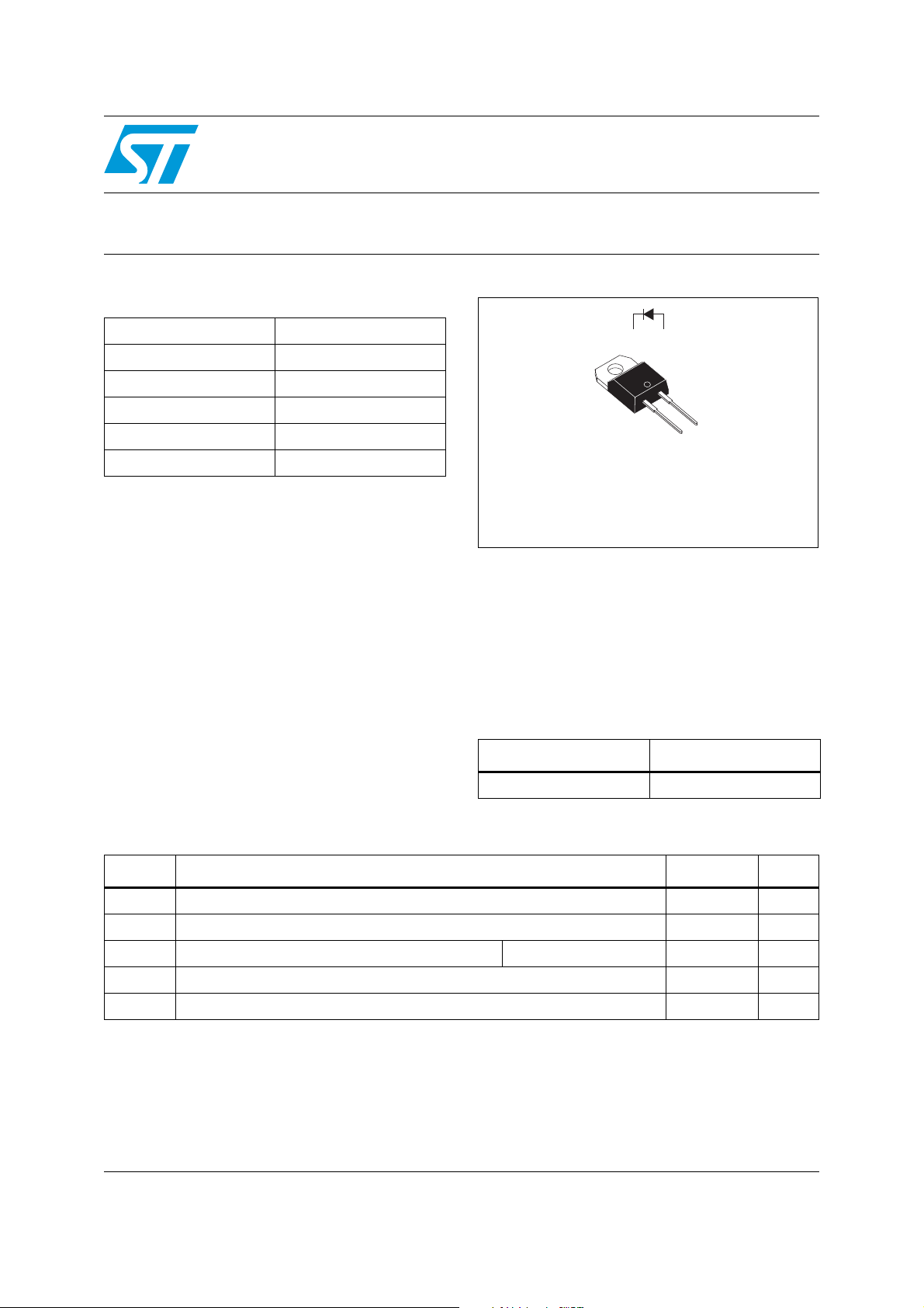
Tandem 600 V hyperfast boost diode

Table 1.

Main product characteristics


IF(AV)

8 A


VRRM

600 V


Tj (max)

150° C


VF (max)

2.24 V


IRM (typ.)

4 A


trr (typ.)

13 ns

Features and benefits

Especially suited as boost diode in continuous mode power factor correctors and hard switching conditions

Designed for high di/dt operation. Hyperfast recovery current to compete with SiC devices. Allows downsizing of mosfet and heatsinks

Internal ceramic insulated devices with equal thermal conditions for both 300 V diodes

Insulation (2500 VRMS) allows placement on same heatsink as mosfet and flexible heatsinking on common or separate heatsink

Static and dynamic equilibrium of internal diodes are warranted by design

Package Capacitance: C = 7 pF

1 2

2

1

Insulated TO-220AC

Description

The TURBOSWITCH “H” is an ultra high performance diode composed of two 300 V dice in series. TURBOSWITCH “H” family drastically cuts losses in the associated MOSFET when run at high dIF/dt.

Table 2. Order codes

Part number

Marking

STTH806DTI STTH806DTI

Table 3.

Absolute ratings (limiting values)


Symbol

Parameter


Value

Unit


VRRM

Repetitive peak reverse voltage


600

V

IF(RMS)

RMS forward voltage


14

A

IFSM

Surge non repetitive forward current

tp = 10 ms sinusoidal

180

A

Tstg

Storage temperature range


-65 to + 150

° C

Tj

Maximum operating junction temperature


150

° C

July 2007

Rev 5

1/7

www.st.com

Characteristics


STTH806DTI


1


Characteristics


Table 4.

Thermal parameter


Symbol

Parameter


Value


Unit


Rth(j-c)

Junction to case thermal resistance


2.6


°C/W

Table 5.

Static electrical characteristics


Symbol

Parameter

Test conditions


Min.

Typ

Max.

Unit


IR

(1)

Reverse leakage current

Tj = 25° C

VR = VRRM


10


µA

Tj = 125° C


15

100


VF

(2)

Forward voltage drop

Tj = 25° C

IF = 8 A


3.6


V

Tj = 150° C


1.95

2.4


1.Pulse test: tp = 100 ms, δ < 2%

2.Pulse test: tp = 380 µs, δ < 2%

To evaluate the conduction losses use the following equation:

P = 1.7 x IF(AV) + 0.087 IF2(RMS)

Table 6.

Dynamic characteristics


Symbol

Parameter


Test conditions

Min

Typ

Max

Unit


IF = 0.5 A, Irr = 0.25 A, IR = 1 A


13


trr

Reverse recovery time

Tj = 25° C

I

F

= 1 A, dI

/dt = - 50 A/µs


30

ns


F


VR = 30 V


IRM

Reverse recovery current


IF = 8 A, VR = 400,


4

5.5


S

Reverse recovery softness factor

T

= 125° C


0.4


A


j

VdIF/dt = - 200 A/µs


Qrr

Reverse recovery charges


50


Table 7.

Turn-on switching characteristics


Symbol

Parameter


Test conditions

Min.

Typ

Max.

Unit


tfr

Forward recovery time

Tj = 25° C

IF = 8 A, dIF/dt = 100 A/µs


200

ns

VFR = 1.1 x VF max


VFP

Forward recovery voltage

Tj = 25° C

IF = 8 A, dIF/dt = 100 A/µs


7

V

2/7

ST STTH806DTI User Manual

STTH806DTI

Characteristics


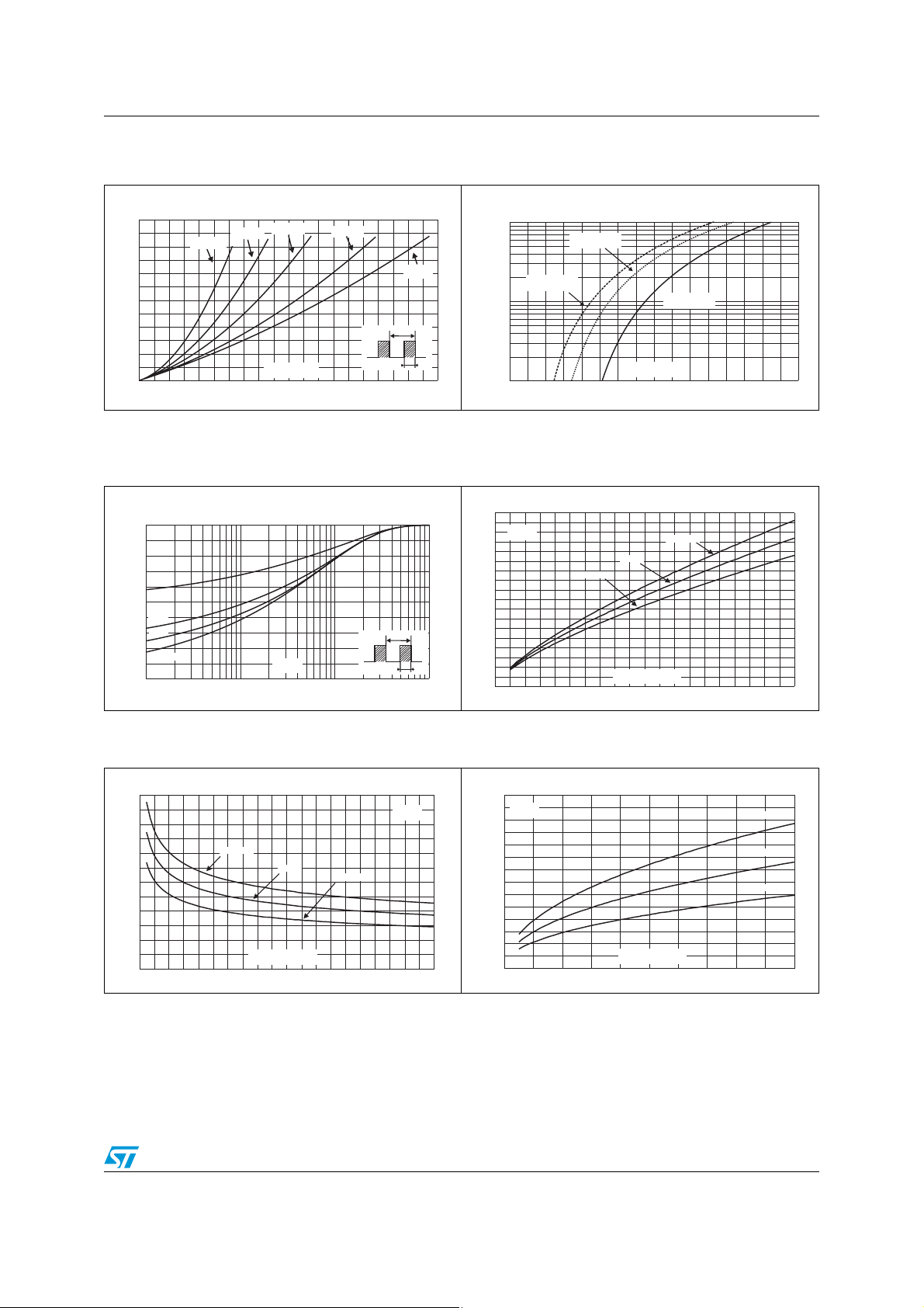
Figure 1. Conduction losses versus average Figure 2.

Forward voltage drop versus

current

forward current

P(W)


IFM(A)


30


δ = 0.2


100


δ = 0.1


δ = 0.5


Tj=125°C


δ = 0.05


25


(maximum values)


20


δ = 1


Tj=125°C


(typical values)


15


10


Tj=25°C


(maximum values)


10


T


5


IF(AV)(A)


δ=tp/T

tp


VFM(V)


0


1


0

1

2

3

4

5

6

7

8

9

10

0

1

2

3

4

5

6

7

8

Figure 3. Relative variation of thermal

Figure 4. Peak reverse recovery current

impedance junction to case

versus dIF/dt (typical values)

versus pulse duration


Zth(j-c)/Rth(j-c)


IRM(A)


9


1.0


8

VR=400V


Tj=125°C


IF=2 x IF(AV)


0.8


7


IF=IF(AV)


6


IF=0.5 x IF(AV)


δ = 0.5


0.6


5


0.4


4


δ = 0.2


δ = 0.1


T

3


0.2


2


Single pulse


tp(s)


δ=tp/T

tp

1


dIF/dt(A/µs)


0.0


0


1E-3

1E-2


1E-1

1E+0


0

50

100

150

200

250

300

350

400

450

500

Figure 5. Reverse recovery time versus dIF/dt Figure 6.

Reverse charges versus dIF/dt

(typical values)

(typical values)

trr(ns)


Qrr(nC)


60


140


VR=400V


VR=400V


Tj=125°C


IF=2 x IF(AV)


Tj=125°C


50


120


40


IF=2 x IF(AV)


100


IF=IF(AV)


IF=IF(AV)


IF=0.5 x IF(AV)


80


30


IF=0.5 x IF(AV)


60


20


40


10


20


dIF/dt(A/µs)


dIF/dt(A/µs)


0


0


0

50

100

150

200

250

300

350

400

450

500

0

100

200

300

400

500

3/7

Loading...
+ 4 hidden pages