

®
HIGH FREQUENCY SECONDARY RECTIFIERS
MAJOR PRODUCTS CHARACTERISTICS
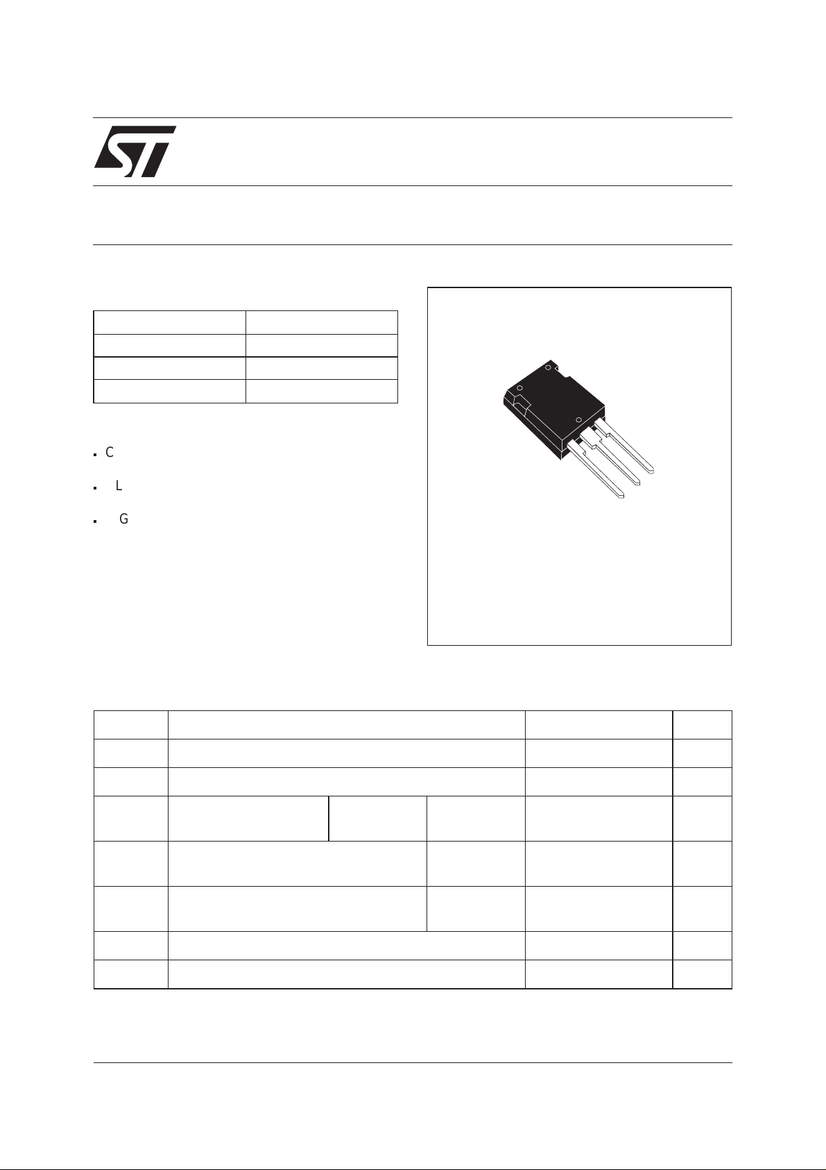
STTH8003CY
I
F(AV)
V
RRM
(max) 1 V
V
F
2x40 A
300 V
trr (max) 60 ns
FEATURES AND BENEFITS
COMBINES HIGHEST RECOVERY AND
n
VOLTAGE PERFORMANCE.
ULTRA-FAST, SOFT AND NOISE-FREE
n
RECOVERY.
n
HIGH OPERATING TEMPERATURE THANKS
A2
K
A1
TO LOW LEAKAGE CURRENT.
DESCRIPTION
Dual rectifiers suited for Switch Mode Power
Max247
Supply and high frequency DC to DC converters.
Packaged in Max247, this device is intended for
use in low voltage, high frequency inverters, free
wheeling operation, welding equipment and
telecom power supplies.
ABSOLUTE RATINGS (limiting values)
Symbol Parameter Value Unit
V
RRM
I
F(RMS)
I
F(AV)
Repetitive peak reverse voltage
RMS forward current
Average forward cur-
rent
I
FSM
I
RSM
T
stg
Tj
September 2002 - Ed: 3A
Surge non repetitive forward current tp = 10 ms
Non repetitive avalanche current tp = 100 µs
Storage temperature range
Maximum operating junction temperature
Tc = 105°C
δ = 0.5
Per diode
Per device
sinusoidal
square
300 V
50 A
40
A
80
400 A
4A
-55 +175 °C
+ 175 °C
1/5
STTH8003CY
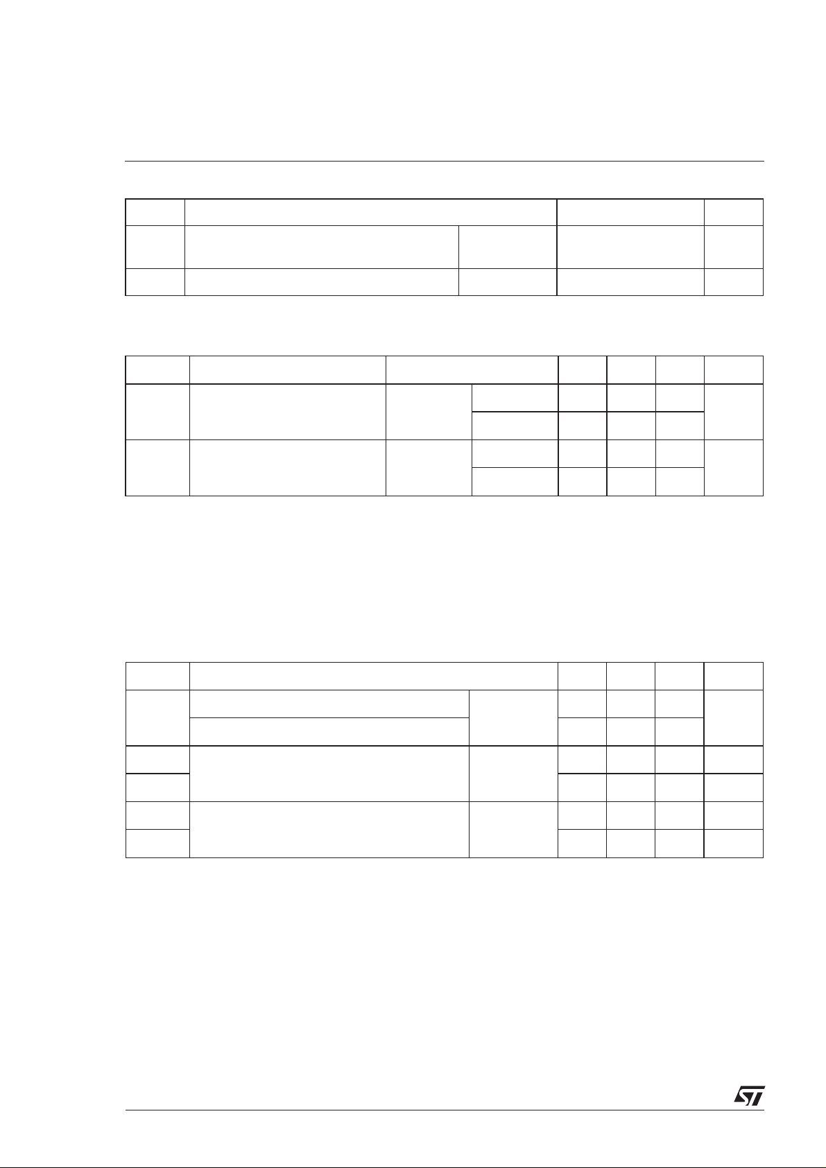
THERMAL RESISTANCES
Symbol Parameter Value Unit
R
R
th (j-c)
th (c)
Junction to case thermal resistance Per diode
Total
Coupling
0.8
°C/W
0.5
0.2 °C/W
STATIC ELECTRICAL CHARACTERISTICS
Symbol Parameter Tests Conditions Min. Typ. Max. Unit
Reverse leakage current V
*
I
R
Forward voltage drop I
**
V
F
= 300 V Tj = 25°C
R
Tj = 125°C
= 40A Tj=25°C
F
Tj = 125°C
80 µA
80 800
1.25 V
0.85 1
Pulse test : * tp=5ms,δ<2%
** tp = 380 µs, δ <2%
To evaluate the maximum conduction losses use the following equation :
P=0.75xI
F(AV)
+ 0.0062 I
F(RMS)
2
DYNAMIC ELECTRICAL CHARACTERISTICS
Symbol Tests Conditions Min. Typ. Max. Unit
= 0.5 A Irr = 0.25 A IR= 1 A Tj = 25°C
S
trr
I
RM
factor
tfr
I
F
=1A dIF/dt=-50A/µsVR=30V
I
F
Vcc = 200 V IF=40A dIF/dt = -200 A/µs Tj = 125°C
I
=40A dIF/dt = 200 A/µs,
F
Tj = 25°C
0.3 -
50 ns
60
13 A
450 ns
VFR= 1.1xVFmax
V
FP
5V
2/5
 Loading...