

®
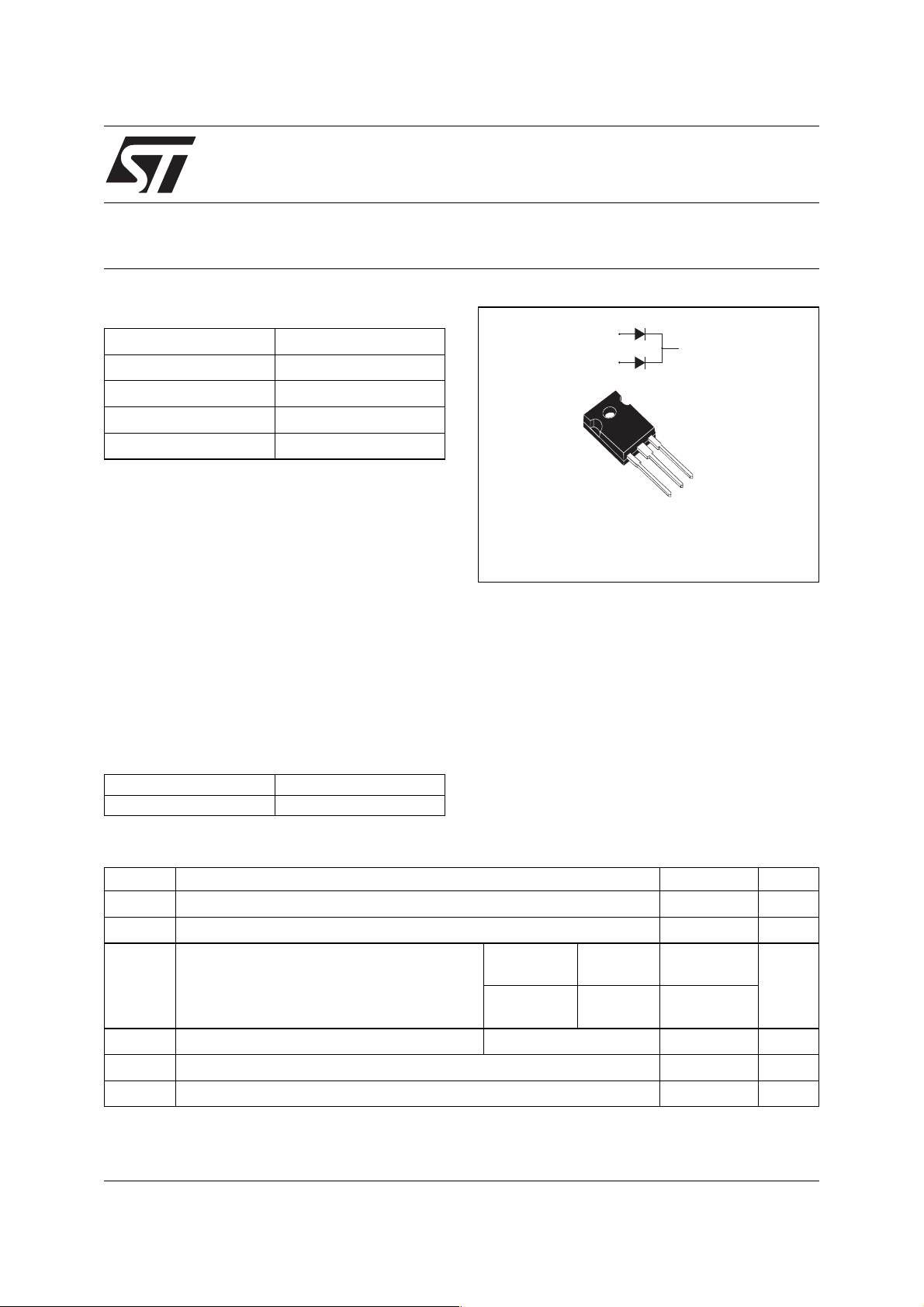
TURBO 2 ULTRAFAST HIGH VOLTAGE RECTIFIER
Table 1: Main Product Characteristics
I
F(AV)
V
RRM
T
j
VF (typ)
(max)
t
rr
Up to 2 x 40 A
600 V
175°C
1.0 V
65 ns
STTH60L06C
A1
K
A2
FEATURES AND BENEFITS
■ Ultrafast switching
■ Low reverse current
■ Low thermal resistance
■ Reduces switching & conduction losses
TO-247
STTH60L06CW
A1
A2
K
DESCRIPTION
The STTH60L06, which is using ST Turbo 2 600V
technology, is specially suited for use in switching
power supplies, and industrial applications, as
rectification and discontinuous mode PFC boost
diode.
Table 2: Order Codes
Part Number Marking
STTH60L06CW STTH60L06CW
Table 3: Absolute Ratings (limiting values, per diode)
Symbol Parameter Value Unit
V
RRM
I
F(RMS)
I
F(AV)
I
FSM
T
T
Repetitive peak reverse voltage 600 V
RMS forward voltage 60 A
Average forward current
δ = 0.5
Tc = 125°C
Tc = 110°C
Tc = 100°C
Tc = 80°C
Per diode
Per device
Per diode
Per device
Surge non repetitive forward current tp = 10ms sinusoidal 210 A
Storage temperature range -65 to + 175 °C
stg
Maximum operating junction temperature 175 °C
j
30
60
40
80
A
September 2004 REV. 1
1/6
STTH60L06C
Table 4: Thermal Resistance
Symbol Parameter Value (max). Unit
R
th(j-c)
R
th(c)
When the diodes 1 and 2 are used simultaneously:
∆ Tj(diode 1) = P(diode 1) x R
Table 5: Static Electrical Characteristics (per diode)
Symbol Parameter Test conditions Min. Typ Max. Unit
IR * Reverse leakage current Tj = 25°C VR = V
VF ** Forward voltage drop Tj = 25°C IF = 30A 1.55 V
Pulse test: * tp = 5 ms, δ < 2%
To evaluate the conduction losses use the following equation: P = 0.95 x I
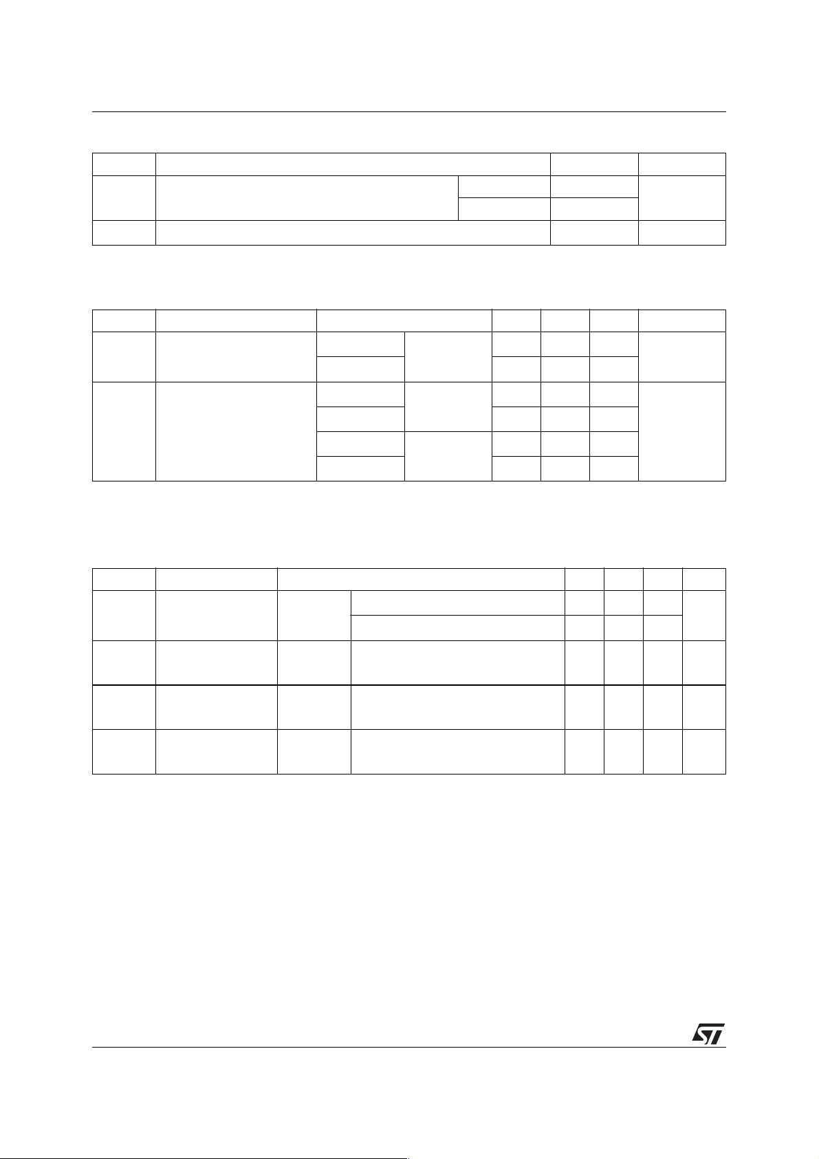
Table 6: Dynamic Characteristics (per diode)
Junction to case Per diode 1.05 °C/W
Total 0.68
Coupling 0.3 °C/W
(Per diode) + P(diode 2) x R
th(j-c)
th(c)
RRM
25 µA
Tj = 150°C 80 800
Tj = 150°C 1.0 1.25
Tj = 25°C IF =60A 1.78
Tj = 150°C 1.24 1.55
** tp = 380 µs,
δ < 2%
F(AV)
+ 0.010 I
F2(RMS)
Symbol Parameter Test conditions Min. Typ Max. Unit
V
I
RM
t
t
Reverse recovery
rr
time
Reverse recovery
current
Forward recovery
fr
time
Forward recovery
FP
voltage
Tj = 25°C IF = 0.5A Irr = 0.25A IR =1A 65 ns
IF = 1A dIF/dt = 50 A/µs VR =30V 65 90
Tj = 125°C IF = 30A VR = 400V
11.5 16 A
dIF/dt = 100 A/µs
Tj = 25°C IF = 30A dIF/dt = 100 A/µs
VFR = 1.1 x V
Fmax
Tj = 25°C IF = 30A dIF/dt = 100 A/µs
VFR = 1.1 x V
Fmax
500 ns
2.5 V
2/6
 Loading...