

ST STTH40P03S User Manual
®
STTH40P03S
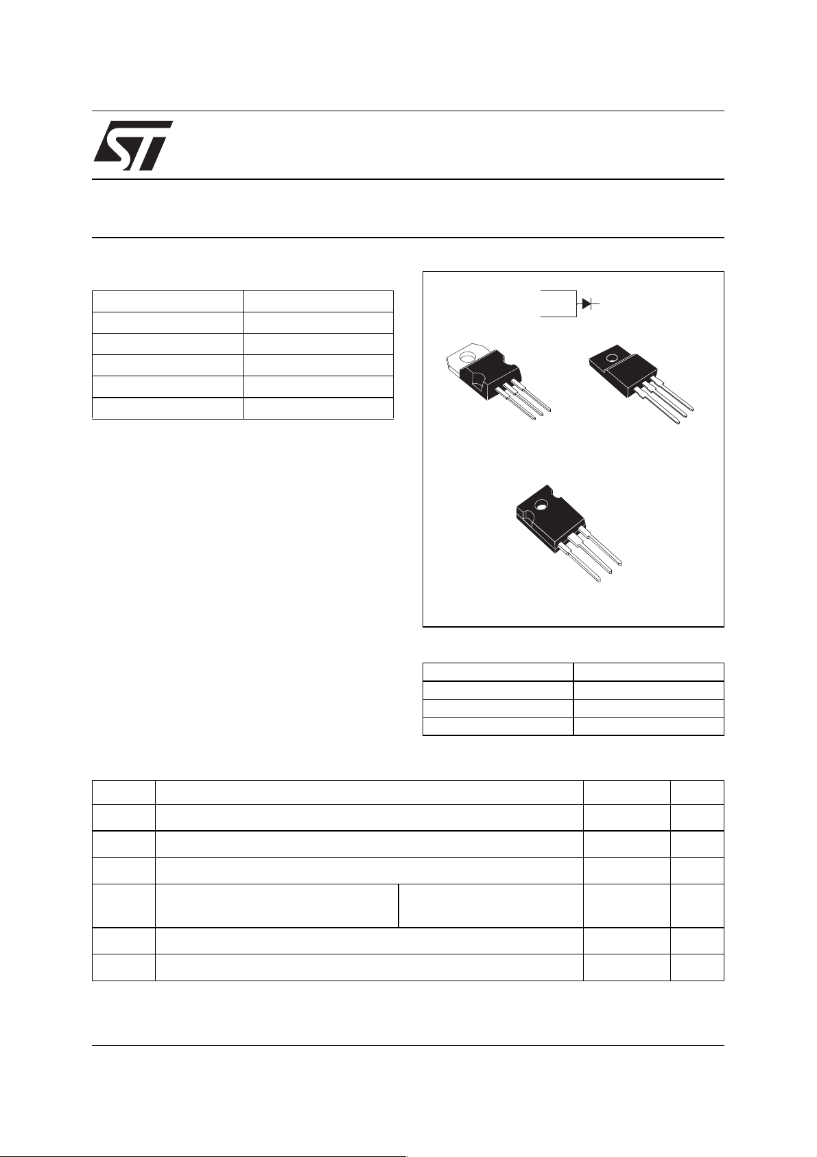
ULTRAFAST RECTIFIER PDP ENERGY RECOVERY
Table 1: Main Product Characteristics
V
I
FP
RM
V
I
F(AV)
V
RRM
(typ)
(typ)
T
(typ)
F
j
40 A
300 V
2.5 V
5 A
175°C
0.9 V
FEATURES AND BENEFITS
■ Ultrafast recovery allowing High Sustain
Frequency
■ Decrease charge evacuation time (t
clamp
) in the
inductance (see figures 1 and 2)
■ Minimize switching-on and total power losses
■ Increase luminuous efficiency and brightness
■ Soft and noise-free recovery
■ High surge capability
■ High junction temperature
DESCRIPTION
The STTH40P03S is an Ultrafast Recovery Power
Rectifier dedicated to energy recovery in PDP
application.
The key parameters of the D
diode for the
ERC
energy recovery cicuit have been optimized in
order to decrease power losses.
A
A
A
TO-220AB
STTH40P03ST
A
K
K
TO-220FPAB
STTH40P03SFP
A
K
A
TO-247
STTH40P03SW
Table 2: Order Codes
Part Number Marking
STTH40P03ST STTH40P03S
STTH40P03SFP STTH40P03S
STTH40P03SW STTH40P03S
A
K
A
Table 3: Absolute Ratings (limiting values)
Symbol Parameter Value Unit
V
RRM
I
F(RMS)
I
F(AV)
I
FRM
T
T
July 2005 REV. 1
.
Repetitive peak reverse voltage 300 V
RMS forward voltage 80 A
Average forward current 40 A
Repetitive peak forward current
Storage temperature range -65 to + 175 °C
stg
Maximum operating junction temperature 175 °C
j
F = 200kHz, t
Sinusoidal waveform
= 500ns
p
120 A
1/8

STTH40P03S
Table 4: Thermal Parameters
Symbol Parameter Value Unit
R
Z
th(j-c)
th(j-c)
Junction to case
Transient thermal resistance at 1µs 0.002 °C/W
Table 5: Static Electrical Characteristics
Symbol Parameter Test conditions Min. Typ Max. Unit
*
I
R
V
F
Pulse test: * tp = 5 ms, δ < 2%
To evaluate the conduction losses use the following equation: P = 0.88 x I
Reverse leakage current
**
Forward voltage drop
** tp = 380 µs,
δ < 2%
TO-220AB / TO-247 1.15
TO-220FPAB 4.5
= 25°C VR = V
T
j
T
= 125°C 0.05 0.5 mA
j
= 25°C
T
j
T
= 125°C
j
= 25°C
T
j
T
= 125°C
j
I
I
= 20A
F
= 40A
F
F(AV)
RRM
+ 0.0135 I
0.9 1.15
1.1 1.8
F2(RMS)
50
1.5
1.42
°C/W
µA
V
V
Table 6: Switching Characteristics
Symbol Parameter Test conditions Min. Typ Max. Unit
S
I
RM
factor
Reverse recovery current
Softness factor 0.5 -
Tj = 100°C IF = 40A VR = 100V
dI
/dt = 200 A/µs
F
56.5 A
2/8
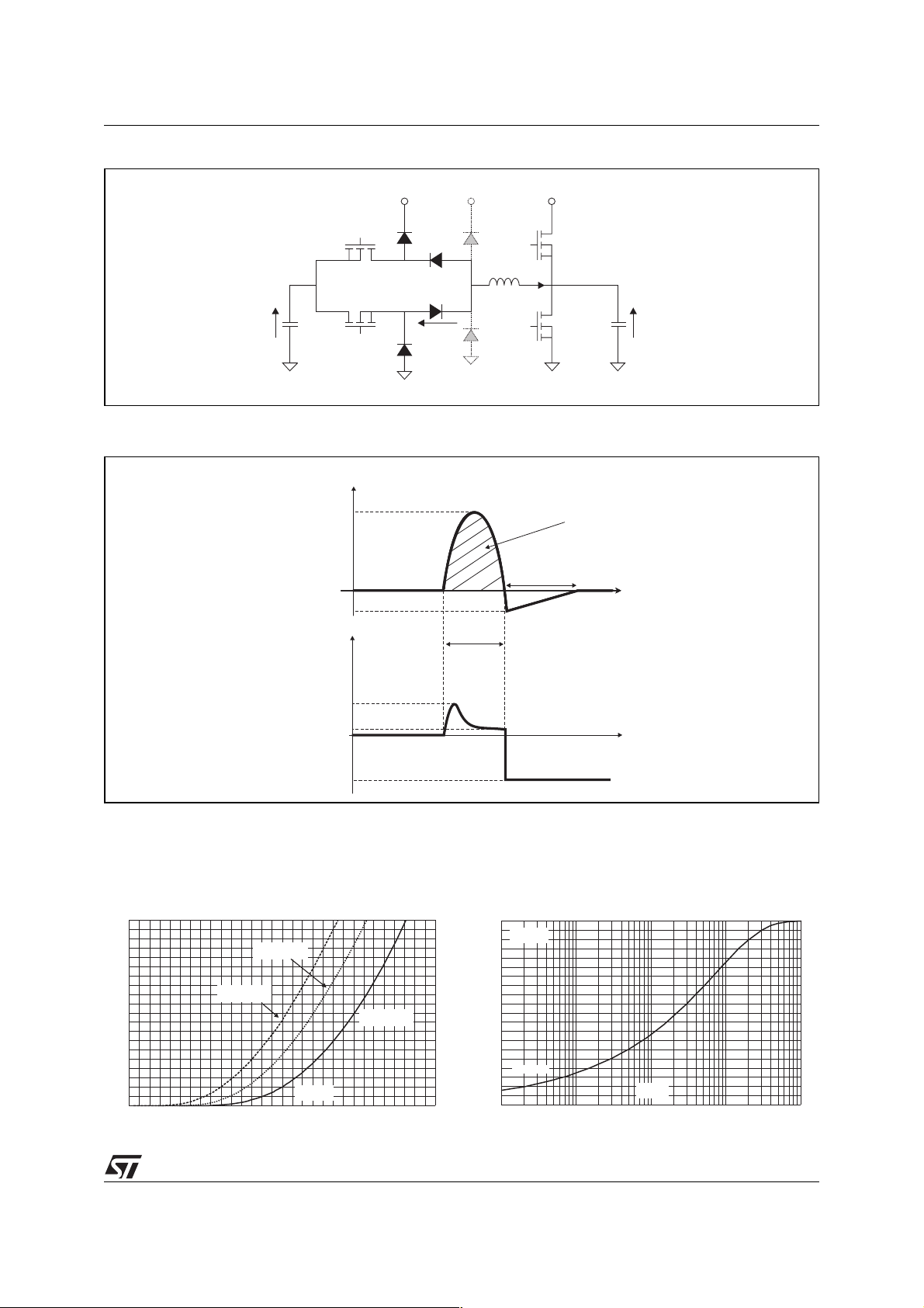
Figure 1: Application Characteristics
STTH40P03S
V/2
C
S
S
Figure 2: Application Waveforms
I
I
RM
V
DERC
V
S
D
CL
2
T
2
T
1
D
ERC
2
D
ERC
1
V
DERC
1
D
CL
1
V
S
T
3
L
i
L
C
T
panel
4
V
Cpanel
GND
i
L
P
t
clamp
I
DERC
1
t
t
1
p
V
FP
V
F
V/2
S
Figure 3: Forward voltage drop versus forward
current
I (A)
FM
200
180
160
140
120
100
80
60
40
20
0
0.0 0.2 0.4 0.6 0.8 1.0 1.2 1.4 1.6 1.8 2.0 2.2 2.4 2.6 2.8 3.0
T =125°C
j
(typical values)
T =125°C
j
(maximum values)
V (V)
FM
T =25°C
j
(maximum values)
t
Figure 4: Relative variation of thermal
impedance junction to case versus pulse
duration (TO-220AB / TO-247)
Z/R
th(j-c) th(j-c)
1.0
TO-220AB
TO-247
0.9
0.8
0.7
0.6
0.5
0.4
0.3
0.2
Single pulse
0.1
0.0
1.E-04 1.E-03 1.E-02 1.E-01 1.E+00
t (s)
p
3/8
 Loading...