

STTH30R04
Ultrafast recovery diode
Main product characteristics
I
F(AV)
V
RRM
T
j
(typ) 0.97 V
V
F
t
rr
30 A
400 V
175° C
24 ns
TO-220AC
STTH30R04D
A
A
K
K
A
K
DO-247
STTH30R04W
Features and benefits
K
■ Ultrafast switching
■ Low reverse current
■ Low thermal resistance
■ Reduces switching and conduction losses
■ High junction temperature
■ Insulated package: DOP3I
– Electrical insulation = 2500 V
RMS
Package capacitance = 12 pF
AA
Note:
D2PAK - 2 anode terminals must be shorted on
board.
K
A
2
PAK
D
STTH30R04G
A
A
K
DOP3I
STTH30R04PI
Order codes
Description
The compromise-free, high quality design of this
diode has produced a device with low leakage
current, regularly reproducible characteristics and
intrinsic ruggedness. These characteristics make
it ideal for heavy duty applications that demand
long term reliability.
Table 1. Absolute ratings (limiting values at 25° C, unless otherwise specified)
Symbol Parameter Value Unit
Part Number Marking
STTH30R04D STTH30R04D
STTH30R04G STTH30R04G
STTH30R04G-TR STTH30R04G
STTH30R04W STTH30R04W
STTH30R04PI STTH30R04PI
V
RRM
I
F(RMS)
I
F(AV)
I
FRM
I
FSM
T
Repetitive peak reverse voltage 400 V
RMS forward current 50 A
2
Average forward current, δ = 0.5
TO-220AC / DO-247 / D
DOP3I T
PA K Tc = 120° C
= 90° C
c
Repetitive peak forward current tp = 10 µs, F = 1 kHz 500 A
Surge non repetitive forward current tp = 10 ms Sinusoidal 300 A
Storage temperature range -65 to +175 ° C
stg
Maximum operating junction temperature range -40 to +175 ° C
T
j
30 A
March 2007 Rev 1 1/10
www.st.com

Characteristics STTH30R04
1 Characteristics
Table 2. Thermal parameters
Symbol Parameter Value Unit
RRM
2
PA K 1 . 1 5
15
1.26
1.45
°C/W
µAT
V
R
th(j-c)
Table 3. Static electrical characteristics
Junction to case
DOP3I 1.9
Symbol Parameter Test conditions Min Typ Max Unit
TO-220AC / DO-247 / D
T
= 25° C
j
(1)
I
Reverse leakage current
R
= 100° C 3 30
j
T
= 125° C 15 150
j
= V
V
R
Tj = 25° C
= 15 A
I
F
= 30 A
I
F
(2)
V
1. Pulse test: tp = 5 ms, δ < 2 %
2. Pulse test: tp = 380 µs, δ < 2 %
Forward voltage drop
F
T
= 150° C 0.8 1.0
j
= 25° C
T
j
Tj = 100° C 1.3
T
= 150° C 0.97 1.2
j
To evaluate the conduction losses use the following equation:
P = 0.9 x I
Table 4. Dynamic characteristics
Symbol Parameter
t
rr
I
RM
t
fr
V
FP
+ 0.01 x I
F(AV)
F2(RMS)
Reverse recovery time
Reverse recovery current
Forward recovery time
Forward recovery voltage
Test conditions
I
= 1 A, dIF/dt = -200 A/µs,
F
= 30 V, Tj = 25° C
V
R
= 1 A, dIF/dt = -15 A/µs,
I
F
VR = 30 V, Tj = 25° C
I
= 1 A, IR = 1 A,
F
I
= 0.25 A, Tj = 25° C
RR
= 30 A, dIF/dt = -200 A/µs,
I
F
= 160 V, Tj = 125° C
V
R
= 30 A dIF/dt = 100 A/µs
I
F
VFR = 1.1 x V
= 30 A dIF/dt = 100 A/µs
I
F
= 1.1 x V
V
FR
Fmax
Fmax
, Tj = 25° C
, Tj = 25° C
Min Typ Max Unit
24 35
78 100
ns
50
10 14 A
500 ns
2.9 V
2/10
STTH30R04 Characteristics
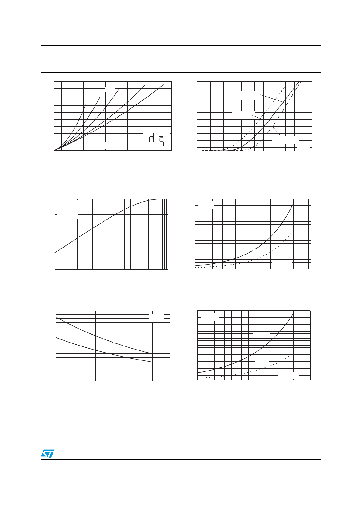
Figure 1. Conduction losses versus
average current
P(W)
50
45
40
35
30
25
20
15
10
5
0
0 5 10 15 20 25 30 35 40
δ=0.05
δ=0.1
δ=0.2
I
(A)
F(AV)
δ=0.5
δ
δ=1
T
=tp/T
Figure 3. Relative variation of thermal
impedance junction to case
versus pulse duration
Zth
/Rth
(j-c)
1.0
0.1
1.E-03 1.E-02 1.E-01 1.E+00
(j-c)
Single pulse
TO-220AC
D²PAK
DO-247
DOP-3I
tp(s)
Figure 5. Reverse recovery time versus
dI
/dt (typical values)
F
tRR(ns)
180
160
140
120
100
80
60
40
20
0
10 100 1000
Tj=125° C
Tj=25° C
dIF/dt(A/µs)
IF= 30 A
V
=320 V
R
Figure 2. Forward voltage drop versus
forward current
IFM(A)
200
180
160
140
120
100
80
60
40
tp
20
0
0.0 0.2 0.4 0.6 0.8 1.0 1.2 1.4 1.6 1.8 2.0 2.2 2.4 2.6
TJ=150°C
TJ=150°C
(Maximum values)
(Maximum values)
TJ=150°C
TJ=150°C
(Typical values)
(Typical values)
(Maximum values)
(Maximum values)
Figure 4. Peak reverse recovery current
versus dI
IRM(A)
22
IF= 30 A
20
=320 V
V
R
18
16
14
12
10
8
6
4
2
0
10 100 1000
/dt (typical values)
F
Tj=125° C
Tj=25° C
dIF/dt(A/µs)
Figure 6. Reverse recovery charges versus
dIF/dt (typical values)
QRR(nC)
750
700
IF= 30 A
=320 V
V
R
650
600
550
500
450
400
350
300
250
200
150
100
50
0
10 100 1000
Tj=125° C
Tj=25° C
TJ=25°C
TJ=25°C
dIF/dt(A/µs)
VFM(V)
3/10
 Loading...