

ST STTH3010-Y User Manual
Features
STTH3010-Y
Automotive ultrafast recovery - high voltage diode
Datasheet − production data
■ AEC-Q101 qualified
■ Ultrafast soft recovery
■ Very low conduction and switching losses
■ High frequency and/or high pulsed current
operation
■ High reverse voltage capability
■ High junction temperature
■ ECOPACK
®
2 compliant component
(STTH3010WY)
Description
The high quality design of this diode has
produced a device with low leakage current,
regularly reproducible characteristics and intrinsic
ruggedness. These characteristics make it ideal
for heavy duty applications that demand long term
reliability like automotive applications.
The improved performance in low leakage
current, and therefore thermal runaway guard
band, is an immediate competitive advantage for
this device.
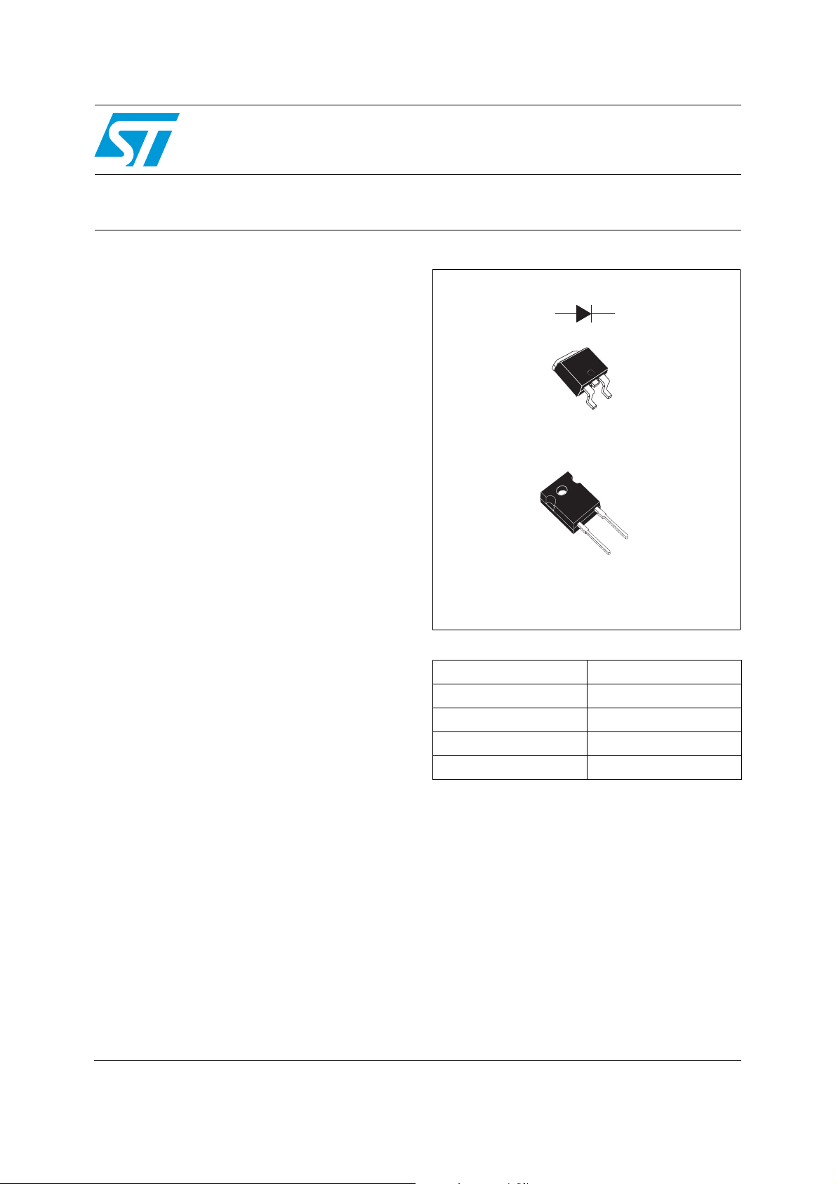
A
K
NC
D2PAK
STTH3010GY
K
DO-247
STTH3010WY
Table 1. Device summary
I
F(AV)
V
RRM
T
j
(typ) 1.30 V
V
F
t
(typ) 42 ns
rr
K
A
A
30 A
1000 V
175 °C
June 2012 Doc ID 018923 Rev 1 1/9
This is information on a product in full production.
www.st.com
9

Characteristics STTH3010-Y
1 Characteristics
Table 2. Absolute ratings (limiting values at 25 °C, unless otherwise specified)
Symbol Parameter Value Unit
V
RRM
I
F(RMS)
I
F(AV)
I
FRM
I
FSM
T
Table 3. Thermal parameters
Repetitive peak reverse voltage 1000 V
Forward rms current 50 A
Average forward current, δ = 0.5
DO-247 T
2
PA K Tc = 105 °C
D
= 105 °C
c
Repetitive peak forward current tp = 5 µs, F = 5 kHz square 300 A
Surge non repetitive forward current tp = 10 ms Sinusoidal 180 A
Storage temperature range -65 to +175 °C
stg
T
Operating junction temperature range -40 to +175 °C
j
30 A
Symbol Parameter Value Unit
DO-247
R
th(j-c)
Table 4. Static electrical characteristics
Junction to case
2
PA K
D
1.1 °C/W
Symbol Parameter Test conditions Min. Typ Max. Unit
(1)
I
R
V
1. Pulse test: tp = 5 ms, δ < 2%
2. Pulse test: t
Reverse leakage current
(2)
Forward voltage drop
F
= 380 µs, δ < 2%
p
To evaluate the conduction losses use the following equation:
P = 1.3 x I
F(AV)
+ 0.013 I
F2(RMS)
Tj = 25 °C
VR = V
I
= 30 A
F
RRM
= 125 °C 10 100
T
j
= 25 °C
T
j
= 150 °C 1.3 1.7
T
j
15
µA
2
VTj = 100 °C 1.4 1.8
2/9 Doc ID 018923 Rev 1
STTH3010-Y Characteristics
Table 5. Dynamic characteristics
Symbol Parameter
Reverse recovery time
t
rr
I
Reverse recovery current
RM
S Softness factor
t
Forward recovery time
fr
V
Forward recovery voltage
FP
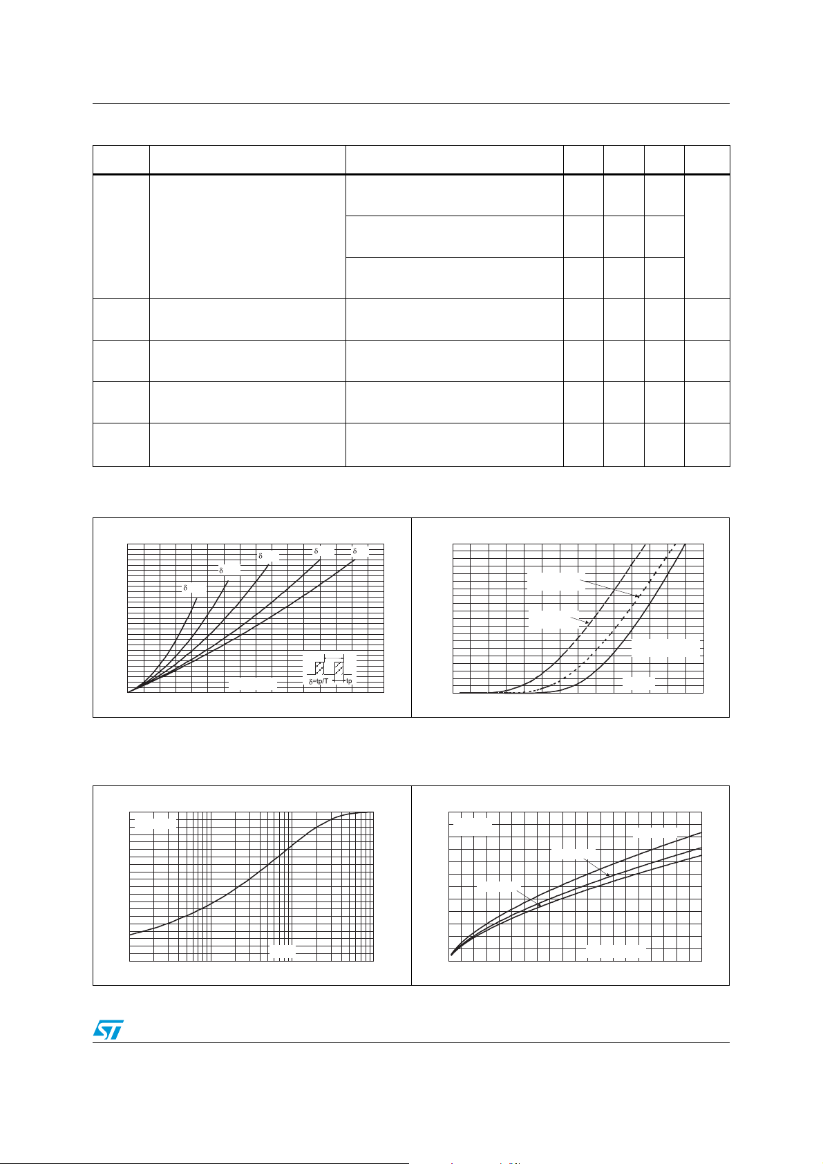
Figure 1. Conduction losses versus
average current
Test conditions
= 1 A, dIF/dt = -50 A/µs,
I
F
VR = 30 V, Tj = 25 °C
I
= 1 A, dIF/dt = -100 A/µs,
F
VR = 30 V, Tj = 25 °C
I
= 1 A, dIF/dt = -200 A/µs,
F
VR = 30 V, Tj = 25 °C
IF = 30 A, dIF/dt = -200 A/µs,
VR = 600 V, Tj = 125 °C
I
= 30 A, dIF/dt = -200 A/µs,
F
VR = 600 V, Tj = 125 °C
IF = 30 A dIF/dt = 100 A/µs
VFR = 1.5 x V
= 30 A, dIF/dt = 100 A/µs,
I
F
= 25 °C
T
j
, Tj = 25 °C
Fmax
Figure 2. Forward voltage drop versus
forward current
Min. Typ Max. Unit
100
53 70
ns
42 55
24 32 A
1
450 ns
5V
P(W)
70
65
60
55
50
45
40
35
30
25
20
15
10
5
0
0 5 10 15 20 25 30 35 40
=0.05
=0.1
I (A)
F(AV)
=0.2
=0.5
T
Figure 3. Relative variation of thermal
impedance junction to case
versus pulse duration
Z/R
th(j-c) th(j-c)
1.0
Single pulse
0.9
0.8
0.7
0.6
0.5
0.4
0.3
0.2
0.1
0.0
1.E-03 1.E-02 1.E-01 1.E+00
t (s)
p
I (A)
FM
=1
200
180
160
140
120
100
80
60
40
20
0
0.0 0.5 1.0 1.5 2.0 2.5 3.0 3.5
Tj=150°C
(Maximum values)
Tj=150°C
(Typical values)
(Maximum values)
V (V)
FM
Tj=25°C
Figure 4. Peak reverse recovery current
versus dI
I (A)
RM
60
VR=600V
=125°C
T
j
50
40
30
20
10
0
IF=0.5 x I
F(AV)
0 50 100 150 200 250 300 350 400 450 500
/dt (typical values)
F
IF= 2 x I
IF= I
F(AV)
dI /dt(A/µs)
F
F(AV)
Doc ID 018923 Rev 1 3/9
 Loading...