How it Works
Log In / Sign Up
Buy Points
How it Works
FAQ
Contact Us
Questions and Suggestions
Users
ST
Loading...
S
STPS61150CW
STPS61170C
STPS61H100C
STPS61L45C
STPS61L60C
STPS640C
STPS660CB(-TR)
STPS745
STPS80150CW
STPS80170C
STPS80H100C
STPS80H100TV
STPS80L60CY
2
STPS8H100
STPS8L30
STPSC1006
STPSC1206
STPSC2006CW
STPSC406
STPSC606
STPSC6H065
STPSC806
STQ2HNK60ZR-AP
STQ2NK60ZR-AP
STR710
2
STR710FZ1
STR710FZ2
STR711FR0
STR711FR1
STR711FR2
STR712FR0
STR712FR1
STR712FR2
STR715FR0
STR730FZ1
STR730FZ2
STR731FV0
STR731FV1
STR731FV2
STR735FZ1
STR735FZ2
STR736FV0
STR736FV1
STR736FV2
STR750
STR9
STR910
STREALIZER-II
STRFNFCA
STRH100N10
STRH40N6
STRH40P10
STRH8N10
STS11NF30L
STS8DNH3LL
STSR2P
STSR2PM
STSR3
STSR30
STSW-STUSB002
STSW-STUSB014
STTH10002
STTH1002C-Y
STTH1003S
STTH102
STTH102-Y
STTH108
STTH10BC065C
STTH10LCD06
STTH10LCD06C
STTH10R04
STTH110
STTH112
STTH12003TV
STTH12010TV
STTH12012TV
STTH1202
STTH120L06TV
STTH120R04TV
STTH1210
STTH1212
STTH12R06
STTH12S06
STTH1302CFP
STTH1302CG
STTH1302CT
STTH1502
STTH1506DPI
STTH1506TPI
STTH1512
STTH15L06
STTH15R06
STTH16003
STTH16BC065C
STTH16L06C
STTH1L06
STTH1R02
STTH1R04
STTH1R06
STTH20002TV
Loading...
Loading...
Nothing found
STRH40N6
User Manual
16 pgs
360.56 Kb
0
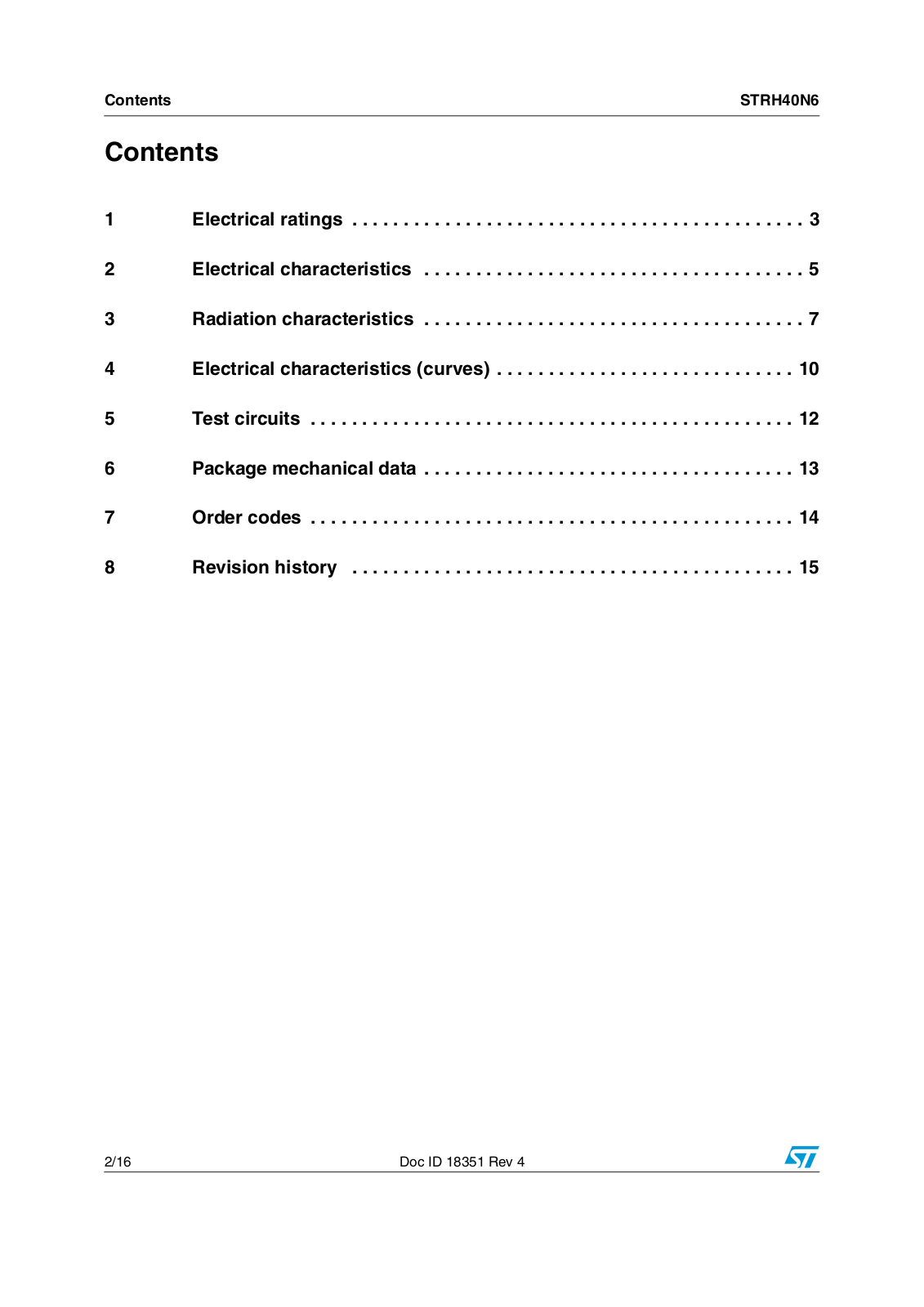
Table of contents
Loading...
ST STRH40N6 User Manual
...
ST User Manual
Download
Specifications and Main Features
Frequently Asked Questions
User Manual
Download
Loading...
+
11
hidden pages
Unhide
You need points to download manuals.
1 point = 1 manual.
You can buy points or you can get point for every manual you upload.
Buy points
Upload your manuals
 Loading...