


Near field communication transceiver
VFQFPN32 5x5 mm
Features
■ Operating modes supported:
– Reader/Writer
– Card Emulation
– Peer-to-Peer
■ Hardware features
– Dedicated internal frame controller
– Highly integrated Analog Front End (AFE)
for RF communications
– Transmission and reception modes
■ RF communication @13.56 MHz
– ISO/IEC 14443 Type A and B in Reader
and Card Emulation modes
– ISO/IEC 15693 in Reader mode
– ISO/IEC 18092 in Reader and Card
Emulation modes
■ Communication interfaces with a Host
Controller
– Serial peripheral interface (SPI) Slave
interface up to 2 Mbps
– Universal asynchronous
receiver/transmitter (UART) up to 2 Mbps
■ 32-lead, 5x5 mm, very thin fine pitch quad flat
(VFQFPN) ECOPACK® package
STRFNFCA
Data brief
Applications
Typical protocols supported:
■ ISO/IEC 14443-3 Type A and B cards and tags
■ ISO/IEC 15693 and ISO/IEC 18000-3M1 tags
■ NFC Forum tags: Types 1, 2, 3 and 4
■ ST Dual Interface EEPROM
Typical STRFNFCA applications include:
■ Handheld readers (OTP, PIN pad, POS)
– E-payment, physical access control,
transport, and government
■ PC-Link (USB /Serial/PCMCIA)
– E-payment, security access &
authentication, data exchange)
■ USB token
– Security access & authentication, data
exchange
■ Integrated solution (chipset)
■ Keyboard, laptop, set top box, printer, TV, etc.
■ E-payment, data exchange, Bluetooth pairing,
security access
December 2011 Doc ID 022168 Rev 6 1/10
For further information contact your local STMicroelectronics sales office.
www.st.com
1
Description STRFNFCA
STRFNFCA
Host
Interrupt Management
SPI
UART
Controller
(MCU)
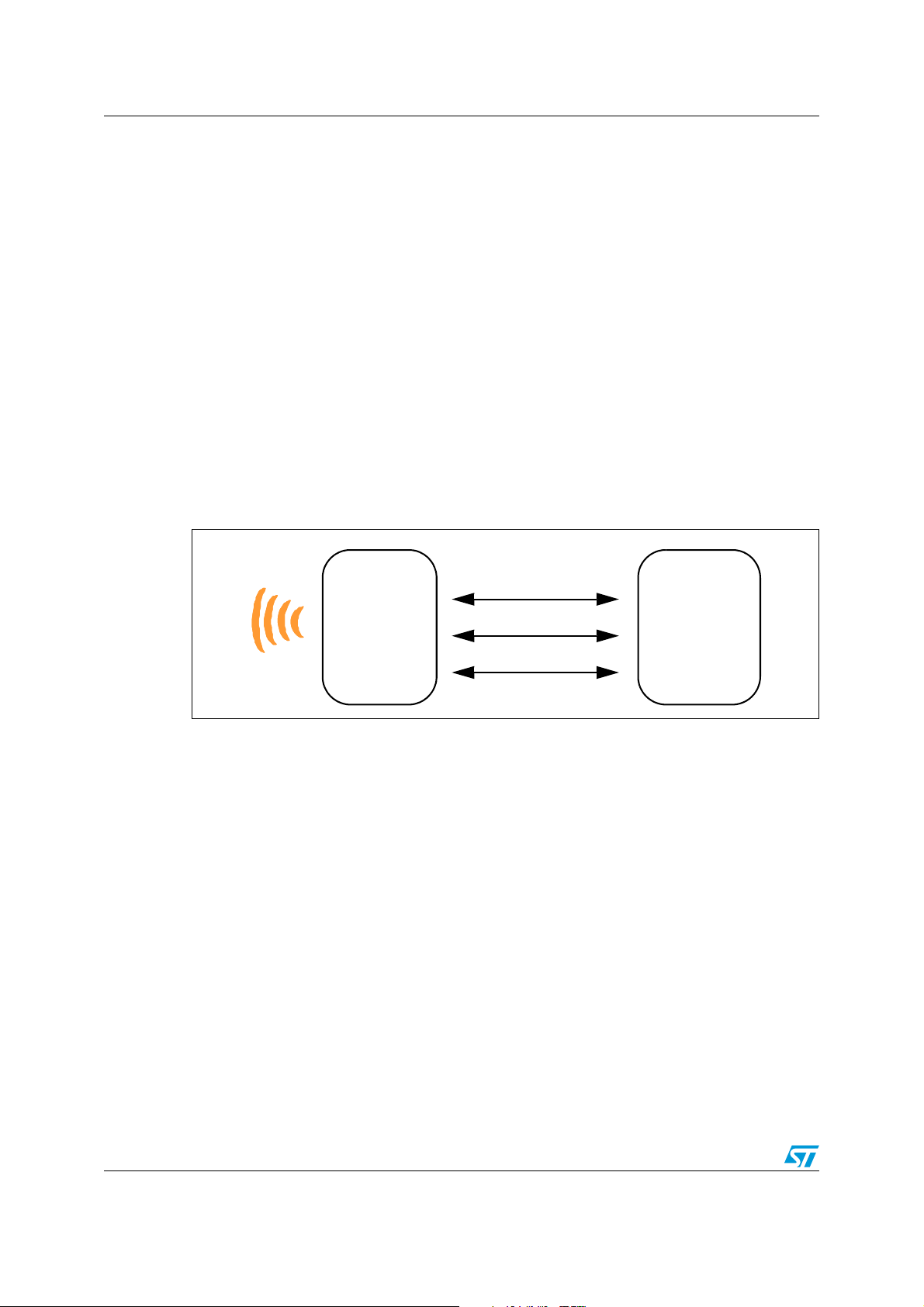
1 Description
The STRFNFCA is an integrated transceiver IC for contactless applications.
The STRFNFCA manages frame coding and decoding in Reader, Card Emulation and
Peer-to-Peer modes for standard applications such as near field communication (NFC),
proximity and vicinity standards.
The STRFNFCA embeds an Analog Front End to provide the 13.56 MHz Air Interface.
The STRFNFCA supports ISO/IEC 14443 Type A and B in Reader and Card Emulation
modes, ISO/IEC 15693 (single or double subcarrier in Reader mode only) and ISO/IEC
18092 protocols in Reader and Card Emulation modes.
The STRFNFCA also supports the reading of NFC Forum Type 1, 2, 3 and 4 tags.
In order to meet environmental requirements, ST offers these devices in different grades of
ECOPACK
specifications, grade definitions and product status are available at: www.st.com.
ECOPACK
Figure 1. STRFNFCA application overview
®
packages, depending on their level of environmental compliance. ECOPACK®
®
is an ST trademark.
2/10 Doc ID 022168 Rev 6
STRFNFCA Description
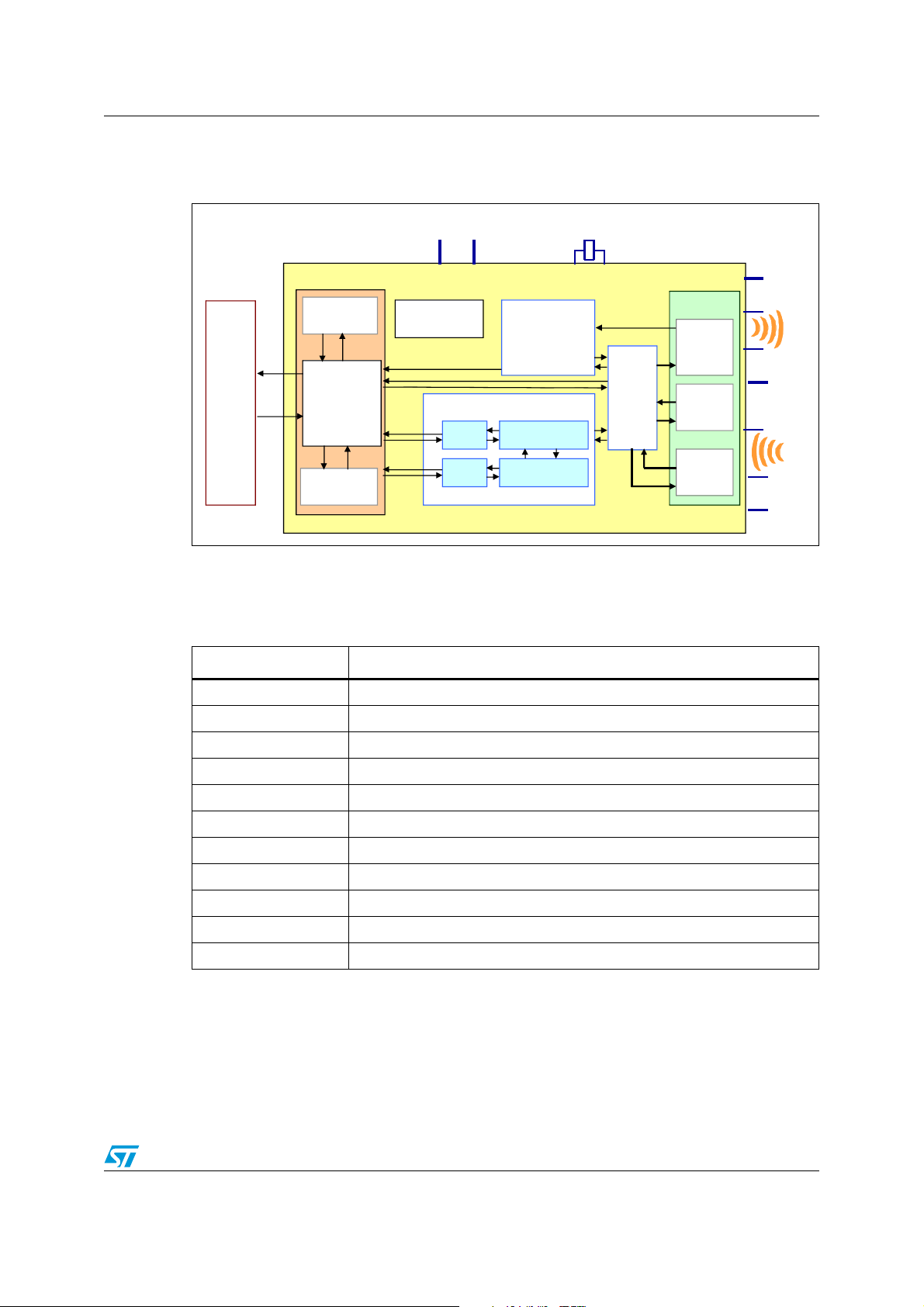
STRFNF CA
Frame Controller
AFE IP
Configurat ion
register
Card
Emulator
14443A/B
18092
Reader
14443A/B
15693
18092
Digit al
Field
Detec tor
Time r Accelerators
Encoder/DecoderFIFO
AFE
Signal
Mux
Mod/
Demod
Fie ld
Detector
Status
registers
User interfac e
(Set @ POR)
SPI: MISO, MOSI,
SS, and SCK
UART: RX and TX
IRQ co ntro l
Power & Cl ock
Management
Host
(User
side)
Xin Xout
TX1
TX2
RX2
RX1
IO_1
IO_8
VPS_TX
GND_ TX
VPS_Main GND_Dig
GND_RX
27.12 MHz
1.1 Block diagram
Figure 2. STRFNFCA block diagram
1.2 List of terms
Table 1. List of terms
Term Meaning
DAC Digital analog converter
GND Ground
HFO High frequency oscillator
LFO Low frequency oscillator
MCU Microcontroller unit
RFU Reserved for future use
SPI Serial peripheral interface
t
L
t
REF
UART Universal asynchronous receiver-transmitter
WFE Wait for event
Low frequency period
Reference time
Doc ID 022168 Rev 6 3/10

Pin and signal descriptions STRFNFCA
1
17
25
9
VPS_TX
GND_TX
XOUT
XIN
NC
NC
NC
GND
ST_R1
SSI_1
SPI_MISO
SPI_SS
UART_RX / IRQ_IN
VPS
TX1
TX2
NC
NC
RX1
Shaded area represents the dissipation pad.
(Must be connected to ground.)
RX2
NC
GND_RX
NC
NC
NC
SSI_0
SPI_SCK
SPI_MOSI
NC
NC
ST_R0
UART_TX / IRQ_OUT
2 Pin and signal descriptions
Figure 3. Pinout description
Table 2. Pin descriptions
Pin Pin name
Typ e
(1)
1 TX1 O Driver output 1
2 TX2 O Driver output 2
3 NC Not connected
4 NC Not connected
5 RX1 I Receiver input 2
4/10 Doc ID 022168 Rev 6
6 RX2 I Receiver input 1
7 NC Not connected
8 GND_RX P Ground (analog)
9 ST_R0 O ST Reserved
10 NC Not connected
11 NC Not connected
12 UART_RX / IRQ_IN
13 VPS P Main power supply
(2)
I UART receive pin Interrupt input
Main function Alternate function
(2)

STRFNFCA Pin and signal descriptions
Table 2. Pin descriptions (continued)
Pin Pin name
Typ e
(1)
Main function Alternate function
14 UART_TX / IRQ_OUT
15 SPI_SS
O UART transmit pin Interrupt output
I SPI Slave Select (active low)
16 SPI_MISO O SPI Data, Slave Output
17 SPI_MOSI I SPI Data, Slave Input
(3)
18 SPI_SCK I SPI serial clock
19 SSI_0 I
20 SSI_1 I
21 ST_R1 I ST Reserved
Select serial communication
interface
Select serial communication
interface
(4)
22 GND P Ground (digital)
23 NC Not connected
24 NC Not connected
25 NC Not connected
26 NC Not connected
27 NC Not connected
28 NC Not connected
29 XIN Crystal oscillator input
30 XOUT Crystal oscillator output
31 GND_TX P Ground (RF drivers)
32 VPS_TX P Power supply (RF drivers)
1. I: Input, O: Output, and P: Power
2. Must add a capacitor to ground.
3. Must not be left floating.
4. Must be connected to V
PS
.
(3)
Doc ID 022168 Rev 6 5/10

Command summary STRFNFCA
3 Command summary
3.1 Command format
Fields <Cmd>, <RespCode> and <Len> are always 1 byte long. <Data> can be from 0 to
255 bytes.
● Direction: MCU to STRFNFCA
<CMD><Len><Data>
● Direction: STRFNFCA to MCU
<RespCode><Len><Data>
3.2 List of commands
Ta bl e 3 lists the command set available for standard use.
Table 3. List of STRFNFCA commands
Code Command Description
01
02
03
04
05
06
08
09
0A
0D
IDN
PROTOCOL SELECT
POLL FIELD
SENDRECV
LISTEN
SEND
RDREG
WRREG
BAUDRATE
AC FILTER
Requests short information about STRFNFCA and its firmware version.
Select communication protocol and specify some protocol-related
parameters.
Returns the current value of FieldDet flag.
Sends data using previously selected protocol and receive the response
of TAG.
Listens for the data using previously selected protocol.
Sends data using previously selected protocol.
Read the Configuration register.
Writes to the Configuration register.
Sets UART baud rate.
Enables or disables the Anti-collision filter.
STRFNFCA performs a serial interface ECHO command (reply data 0x55
55
ECHO
or stops the Listening state when a listen command has been sent
without error).
Other codes ST Reserved
6/10 Doc ID 022168 Rev 6

STRFNFCA Electrical characteristics
4 Electrical characteristics
4.1 Absolute maximum ratings
Table 4. Absolute maximum ratings
Symbol Parameter Value Unit
VPS_Main Supply voltage –0.3 to 7.0 V
VPS_TX Supply voltage (RF drivers) –0.3 to 7.0 V
V
IO
V
MaxCarrier
T
A
T
STG
V
ESD
P
TOT
1. Depending on the thermal resistance of package.
Input or output voltage relative to ground –0.3 to VPS_Main +0.3 V
Maximum input voltage (pins RX1 and RX2) ±14.0 V
Ambient operating temperature –25 to +85
Ambient operating temperature (RF mode) 0 to +50
Storage temperature (Please also refer to package
specification).
Electrostatic discharge voltage according to
JESD22-A114, Human Body Model
(1)
Total power dissipation per package 1 W
–65 to +150 °C
2000 V
°C
Note: Stresses listed above may cause permanent damage to the device. This is a stress rating
only and functional operation of the device at these or any other conditions above those
indicated in the operational sections of the specification is not implied.
Exposure to absolute maximum rating conditions for extended periods may affect device
reliability.
Doc ID 022168 Rev 6 7/10

Evaluation kit environment STRFNFCA
RX1
TX1
TX2
RX2
STRFNFCA
R
1
R
2
R
3
C
3
C
4
C
5
Antenna
5 Evaluation kit environment
The Evaluation kit includes a complete range of hardware and software components from
STMicroelectronics and third-party suppliers to demonstrate the efficiency of the
STRFNFCA transceiver and help you to develop and debug your applications and evaluate
STMicroelectronics RFID products.
● Tools and design kit
● An evaluation board including an example code
● A set of complete documentation including user manual and antenna
recommendations
Figure 4. Reader and Card mode schematic diagram
8/10 Doc ID 022168 Rev 6

STRFNFCA Revision history
6 Revision history
Table 5. Document revision history
Date Revision Changes
28-Jul-2010 1 Initial release.
15-Sep-2010 2 Removed pin descriptions and command summary.
14-Jun-2011 3 Updated communication interface frequencies.
01-Jul-2011 4 Removed Restricted Distribution document classification.
30-Aug-2011 5 Assigned document publication information.
Modified Features. Updated Table 3: List of STRFNFCA commands
16-Dec-2011 6
and Table 4: Absolute maximum ratings.
Added Section 2: Pin and signal descriptions.
Doc ID 022168 Rev 6 9/10

STRFNFCA
Please Read Carefully:
Information in this document is provided solely in connection with ST products. STMicroelectronics NV and its subsidiaries (“ST”) reserve the
right to make changes, corrections, modifications or improvements, to this document, and the products and services described herein at any
time, without notice.
All ST products are sold pursuant to ST’s terms and conditions of sale.
Purchasers are solely responsible for the choice, selection and use of the ST products and services described herein, and ST assumes no
liability whatsoever relating to the choice, selection or use of the ST products and services described herein.
No license, express or implied, by estoppel or otherwise, to any intellectual property rights is granted under this document. If any part of this
document refers to any third party products or services it shall not be deemed a license grant by ST for the use of such third party products
or services, or any intellectual property contained therein or considered as a warranty covering the use in any manner whatsoever of such
third party products or services or any intellectual property contained therein.
UNLESS OTHERWISE SET FORTH IN ST’S TERMS AND CONDITIONS OF SALE ST DISCLAIMS ANY EXPRESS OR IMPLIED
WARRANTY WITH RESPECT TO THE USE AND/OR SALE OF ST PRODUCTS INCLUDING WITHOUT LIMITATION IMPLIED
WARRANTIES OF MERCHANTABILITY, FITNESS FOR A PARTICULAR PURPOSE (AND THEIR EQUIVALENTS UNDER THE LAWS
OF ANY JURISDICTION), OR INFRINGEMENT OF ANY PATENT, COPYRIGHT OR OTHER INTELLECTUAL PROPERTY RIGHT.
UNLESS EXPRESSLY APPROVED IN WRITING BY TWO AUTHORIZED ST REPRESENTATIVES, ST PRODUCTS ARE NOT
RECOMMENDED, AUTHORIZED OR WARRANTED FOR USE IN MILITARY, AIR CRAFT, SPACE, LIFE SAVING, OR LIFE SUSTAINING
APPLICATIONS, NOR IN PRODUCTS OR SYSTEMS WHERE FAILURE OR MALFUNCTION MAY RESULT IN PERSONAL INJURY,
DEATH, OR SEVERE PROPERTY OR ENVIRONMENTAL DAMAGE. ST PRODUCTS WHICH ARE NOT SPECIFIED AS "AUTOMOTIVE
GRADE" MAY ONLY BE USED IN AUTOMOTIVE APPLICATIONS AT USER’S OWN RISK.
Resale of ST products with provisions different from the statements and/or technical features set forth in this document shall immediately void
any warranty granted by ST for the ST product or service described herein and shall not create or extend in any manner whatsoever, any
liability of ST.
ST and the ST logo are trademarks or registered trademarks of ST in various countries.
Information in this document supersedes and replaces all information previously supplied.
The ST logo is a registered trademark of STMicroelectronics. All other names are the property of their respective owners.
© 2011 STMicroelectronics - All rights reserved
STMicroelectronics group of companies
Australia - Belgium - Brazil - Canada - China - Czech Republic - Finland - France - Germany - Hong Kong - India - Israel - Italy - Japan -
Malaysia - Malta - Morocco - Philippines - Singapore - Spain - Sweden - Switzerland - United Kingdom - United States of America
www.st.com
10/10 Doc ID 022168 Rev 6
 Loading...