


USB interface
USB to JTAG
in circuit
emulator
STR710-EVAL board
Evaluation board
DATASHEET
STR710-EVAL board
High speed JTAG
debug port connection
Main components
■ STR710F processor running at 48 MHz
■ EMI SRAM 4 Mbytes (2M x 16)
■ EMI flash 4 Mbytes (2M x 16)
■ SPI serial flash
2
C EEPROM
■ I
■ LCD display
Features
■ Support for the following interfaces:
● USB
● CAN
● RS232
■ LED displays
■ Buzzer
■ Test buttons
■ JTAG connector
Description
The STR710-EVAL board is a complete
development platform for the ST R71x series. The
STR710-EVAL board is a cost effec tive , fle xible and
open design to demonstrate the capability of the
STR71x series of flash micro-controllers and to
enable ra pid e valuation of the STR71x de v ices and
available peripherals. It includes the high
performance STR710FZ2T6 ARM7TDMI
that boasts 256 Kbytes embed ded flash with “bestin-class” random access time, 64 Kbytes on-chip
high speed SRAM as well as up to 10 serial
communication int erfaces, including USB and CAN.
The STR710-EVAL board include s SRAM and f lash
memory on the EMI to enable full freedom in
development of large programs before custom
hardware is designed. It integrates a 2 x 16 LCD,
LEDs, UART, CAN, USB interfaces, piezo buzzer
and test buttons to create a versatile stand-alone
test platform. A wide choice of third party
development to ol s u pp o rt is re ad i l y available, in
addition to thos e av a ilabl e from ST Microelectr onics .
TM
device
19 September 2005 ADCS 7652091D STMicroelectronics 1/27

STR710-EVAL board
Contents
Chapter 1 Introduction . . . . . . . . . . . . . . . . . . . . . . . . . . . . . . . . . . . . . . . . . . . . . . . . . . . . . .3
1.1 Processor and memory devices on this board . . . . . . . . . . . . . . . . . . . . . . . . . . . . . . . . . . 3
1.2 Board interface connections . . . . . . . . . . . . . . . . . . . . . . . . . . . . . . . . . . . . . . . . . . . . . . . . 4
1.3 Push buttons . . . . . . . . . . . . . . . . . . . . . . . . . . . . . . . . . . . . . . . . . . . . . . . . . . . . . . . . . . . . 4
1.4 Displays . . . . . . . . . . . . . . . . . . . . . . . . . . . . . . . . . . . . . . . . . . . . . . . . . . . . . . . . . . . . . . . . 4
Chapter 2 Hardware . . . . . . . . . . . . . . . . . . . . . . . . . . . . . . . . . . . . . . . . . . . . . . . . . . . . . . . . .5
2.1 Overview . . . . . . . . . . . . . . . . . . . . . . . . . . . . . . . . . . . . . . . . . . . . . . . . . . . . . . . . . . . . . . . 7
2.2 Processor . . . . . . . . . . . . . . . . . . . . . . . . . . . . . . . . . . . . . . . . . . . . . . . . . . . . . . . . . . . . . . 7
2.3 Debug . . . . . . . . . . . . . . . . . . . . . . . . . . . . . . . . . . . . . . . . . . . . . . . . . . . . . . . . . . . . . . . . . 7
2.4 Prototype area . . . . . . . . . . . . . . . . . . . . . . . . . . . . . . . . . . . . . . . . . . . . . . . . . . . . . . . . . . . 7
2.5 Reset . . . . . . . . . . . . . . . . . . . . . . . . . . . . . . . . . . . . . . . . . . . . . . . . . . . . . . . . . . . . . . . . . . 7
2.6 Memory . . . . . . . . . . . . . . . . . . . . . . . . . . . . . . . . . . . . . . . . . . . . . . . . . . . . . . . . . . . . . . . . 7
2.7 Power supplies . . . . . . . . . . . . . . . . . . . . . . . . . . . . . . . . . . . . . . . . . . . . . . . . . . . . . . . . . . 7
2.8 USB full speed interface . . . . . . . . . . . . . . . . . . . . . . . . . . . . . . . . . . . . . . . . . . . . . . . . . . . 8
2.9 CAN interface . . . . . . . . . . . . . . . . . . . . . . . . . . . . . . . . . . . . . . . . . . . . . . . . . . . . . . . . . . . 8
2.10 RS232 serial interfaces . . . . . . . . . . . . . . . . . . . . . . . . . . . . . . . . . . . . . . . . . . . . . . . . . . . . 8
2.11 External analog . . . . . . . . . . . . . . . . . . . . . . . . . . . . . . . . . . . . . . . . . . . . . . . . . . . . . . . . . . 8
2.12 Analog input . . . . . . . . . . . . . . . . . . . . . . . . . . . . . . . . . . . . . . . . . . . . . . . . . . . . . . . . . . . . 8
2.13 LEDs . . . . . . . . . . . . . . . . . . . . . . . . . . . . . . . . . . . . . . . . . . . . . . . . . . . . . . . . . . . . . . . . . . 9
2.14 Option jumper placement . . . . . . . . . . . . . . . . . . . . . . . . . . . . . . . . . . . . . . . . . . . . . . . . . 10
2.15 Option switch settings . . . . . . . . . . . . . . . . . . . . . . . . . . . . . . . . . . . . . . . . . . . . . . . . . . . . 1 2
Chapter 3 Connectors . . . . . . . . . . . . . . . . . . . . . . . . . . . . . . . . . . . . . . . . . . . . . . . . . . . . . .14
3.1 USB . . . . . . . . . . . . . . . . . . . . . . . . . . . . . . . . . . . . . . . . . . . . . . . . . . . . . . . . . . . . . . . . . . 14
3.2 CAN bus connector . . . . . . . . . . . . . . . . . . . . . . . . . . . . . . . . . . . . . . . . . . . . . . . . . . . . . . 14
3.3 External analog . . . . . . . . . . . . . . . . . . . . . . . . . . . . . . . . . . . . . . . . . . . . . . . . . . . . . . . . . 14
3.4 RS232 serial data connector . . . . . . . . . . . . . . . . . . . . . . . . . . . . . . . . . . . . . . . . . . . . . . . 15
3.5 DEBUG . . . . . . . . . . . . . . . . . . . . . . . . . . . . . . . . . . . . . . . . . . . . . . . . . . . . . . . . . . . . . . . 15
Chapter 4 Schematics . . . . . . . . . . . . . . . . . . . . . . . . . . . . . . . . . . . . . . . . . . . . .16
Revision history . . . . . . . . . . . . . . . . . . . . . . . . . . . . . . . . . . . . . . . . . . . . . . . . . . . . . . . . . . . . . .26
2/27 STMicroelectroni cs ADCS 7652091D DATASHEET

STR710-EVAL board 1 Introduction
1 Introduction
STMicroelectronics is a global independent semiconductor company that designs, develops,
manufac tures a nd mark e ts a broad r ange of semi condu ctor int egr at ed circ uits an d di screte devices
used in a wide variety of applications.
The STR710-EVAL board is based on the STR710FZ2T6, a highly integrated micro controller,
running at 48 MHz that combines the popular ARM7TDMI
TM
32-bit RISC CPU with 256 Kbytes of
embedded flash, 64 Kbytes of high speed SRAM, and numerous on-chip peripherals.
This board is intended as low cost development platform to demons trate the capability of the
STR71x series of flash micr o-con troller s and t o ena bl e ra pid e valuation of the STR71x devic es and
available peripherals.
The STR710-EVAL board has 4 Mbytes of SRAM, and 4 Mbytes of flash on EMI, 1-Mbit SPI serial
flash and 8-kbits EEPROM. It s upports USB, CAN and RS232 inte rfaces. The on-board chip
STR710FZ2T6 is an ARM7TDMI
TM
32-bit RISC micro-controller.
This board includes a 2x16 programmable LCD display supported by reset, next and select push
buttons.
Because the STR710FZ2T6 is the super set of the STR71xF series, with 144-pin, EMI, 256 Kbytes
of flash and 64 Kbytes of SRAM, an alternative use of the STR710-EVAL board is as an evaluation
platform for STR711F and STR712F devices.
The hardware pl atform of the STR710F series is supported by an extensive software support
package, including de vice drivers in ANS I C source form and demonstration softw are. It is flashe d
with a demonstr ation appli catio n that sho ws the b asic f e atures o f the de vic e. De v el opment too ls are
readily available. This is complimented by a range of third party real-t ime OS and middleware.
Design schematics can also be supplied in elect r onic format to those customers with compatible
design env i r on m e nts.
1.1 Processor and memory devices on this board
● STR710FZ2T6 ARM7TDMI
➢ 144-pin TQFP version,
➢ 256 Kbytes flash program memory (100 ,0 00 cycle s enduran ce),
➢ 64 Kbytes RAM,
➢ embedded 1.8 V voltage regulator for core supply (options to use the on-board 1.8 V
regulator allows full speed operations,
➢ nested interrupt controller.
● External memory interfac e:
➢ flash (bank 0) 4 Mbytes arranged as 2M x 16: IC12,
➢ SRAM (bank 1) 4 Mbytes arranged as 2M x 16: IC14, IC15.
● Clocking:
➢ +3.3 V surface mounted 16 MHz oscillator provides the main clock source,
➢ RTC real-time cl ock for wakeup from standby mode with embedded 32 KHz oscillator.
● Serial ROMs:
➢ 1-Mbit SPI serial flash connected to the buffered serial peripheral interface (BSPI): IC11,
2
➢ I
C EEPROM: 8-kbit EEPROM connected to the I2C0 interface: IC9.
TM
processor running at 48 MHz, IC13:
DATASHEET ADCS 7652091D STMicroelectr o nics 3/27

1 Introduction STR710-EVAL board
1.2 Board interface connections
Diagrams and wiring desc riptions for these connectors are provided in Section 4: Sche mat ics on
page 16. The following connections are supported by the board:
● USB, support USB device using a type B connector: CN3,
● CAN uses a single 9 D-type conn ector with micros witch selectable low or high speed
transceiver: CN1,
● UART0 (Rx and Tx only) connected to a 9-way male D-type RS232 connector: CN7,
● UART1 and 2 (Rx and Tx only) switch selectable, connected to a 9-way male D-type RS232
connector: CN8 ,
● JTAG, 20 pin IDC connector: CN9,
● Piezo buzzer: SPKR1,
● variab le resistor, voltage range 0 to 2. 5 V: R63,
● protot y p e ar e a: GD1,
● test points, various test points are located throu ghout the board, for details see Section 4:
Schematics on page 16,
● external analog: CN6,
● main power supply: CN2.
1.3 Push buttons
The following push buttons are provided:
● reset, board reset: SW12,
● wakeup, push button to bring processor out of low power mode: SW11,
● select, programmable switch: SW4,
● next, programmable s w itch: SW3.
1.4 Displays
The following LCD and LEDs are provided:
● LCD display, 2x16 LCD display connected to a par allel EMI LCD interface; green back light
display: LCD1,
● surface mount red, +5 V and +3. 3 V power indic ators: LD1, LD2,
● surfac e mount orange , USB powered: LD7,
● surface mount orange indicates standby status: LD21,
● bi-color red/green: LD20,
● low consumption LEDs red: LD3, LD4, LD5, LD6, LD8,LD9, LD10, LD11, LD12, LD13, LD14,
LD15, LD16, LD17, LD18, LD19.
Note: The LCD I
2
C0 connection may be used, although the I2C0 connector is not fitt ed.
4/27 STMicroelectroni cs ADCS 7652091D DATASHEET

STR710-EVAL board 2 Hardware
2 Hardware
LD 12
JTAG
CN9
LD 16
LD 17
LD 18
LD 19
LD 13
LD 14
LD 15
Prototype area GDI
LD 8
LD 9
LD 10
LD 11
LD 3
LD 4
LD 5
LD 6
CAN CN1
RS232-A
UART 0
Rx and Tx only
CN7
External
analog CN6
Variable
resistor R63
RS232-B
UART 1 or 2
Switch selectable
Rx and Tx only CN8
LD20
Buzzer
WAKEUP
push button
LD21
WAKE
STR710FZ2T6
ARM7TDMI
TM
NXT
SPI serial
flash
1.8 V
regulator
LD7
USB CN3
LD2
+3.3 V
regulator
I2C EEPROM
SRAM
IC15, IC14
LD1
DC power
filter IC1
+5 V power
CN2
Push buttons
Board reset
push button
RST
Flash
IC12
LCD display EM I
SEL
Figure 1: STR710-EVAL board layout block diagram
DATASHEET ADCS 7652091D STMicroelectr o nics 5/27

2 Hardware STR710-EVAL board
In-circuit
emulator
RS232
Rx and Tx
RS232
Rx and Tx
switchable
JTAG
UART0
UART
1 or 2
Prototype area
EMI
LEDs
CAN
USB
Flash
SRAM
Variable
resistor
Piezzo
Buzzer
5 V power
Analog
Audio out
Figure 2: STR710-EVAL board system blo ck diagram
LCD
2
C
I
EEPROM
SPI
serial
flash
6/27 STMicroelectroni cs ADCS 7652091D DATASHEET

STR710-EVAL board 2 Hardware
2.1 Overview
The STR710-EVAL board is a general purpose eval uation platform with USB, CAN (cont roller area
network), and RS232 int erfaces.
2.2 Processor
The board supports the STR710FZ2T6 ARM7TDMITM silicon - 144-pin TQFP version. This chip
runs at a frequency of 48 MHz.
Boot modes and configuration options are set using microswitches.
2.3 Debug
Software de bug is by a standard 20-pin JTAG connection. T his may connec t to a standard USB to
JTAG in-circuit emulator.
2.4 Prototype area
A 2.54 x 2.54 mm gridded area of 1mm holes is available for prototyping using wire wrap or similar
prototyping te chniques.
2.5 Reset
The Reset sources are:
● power on reset,
● push button rese t,
● JTAG reset from an in-circuit emulator.
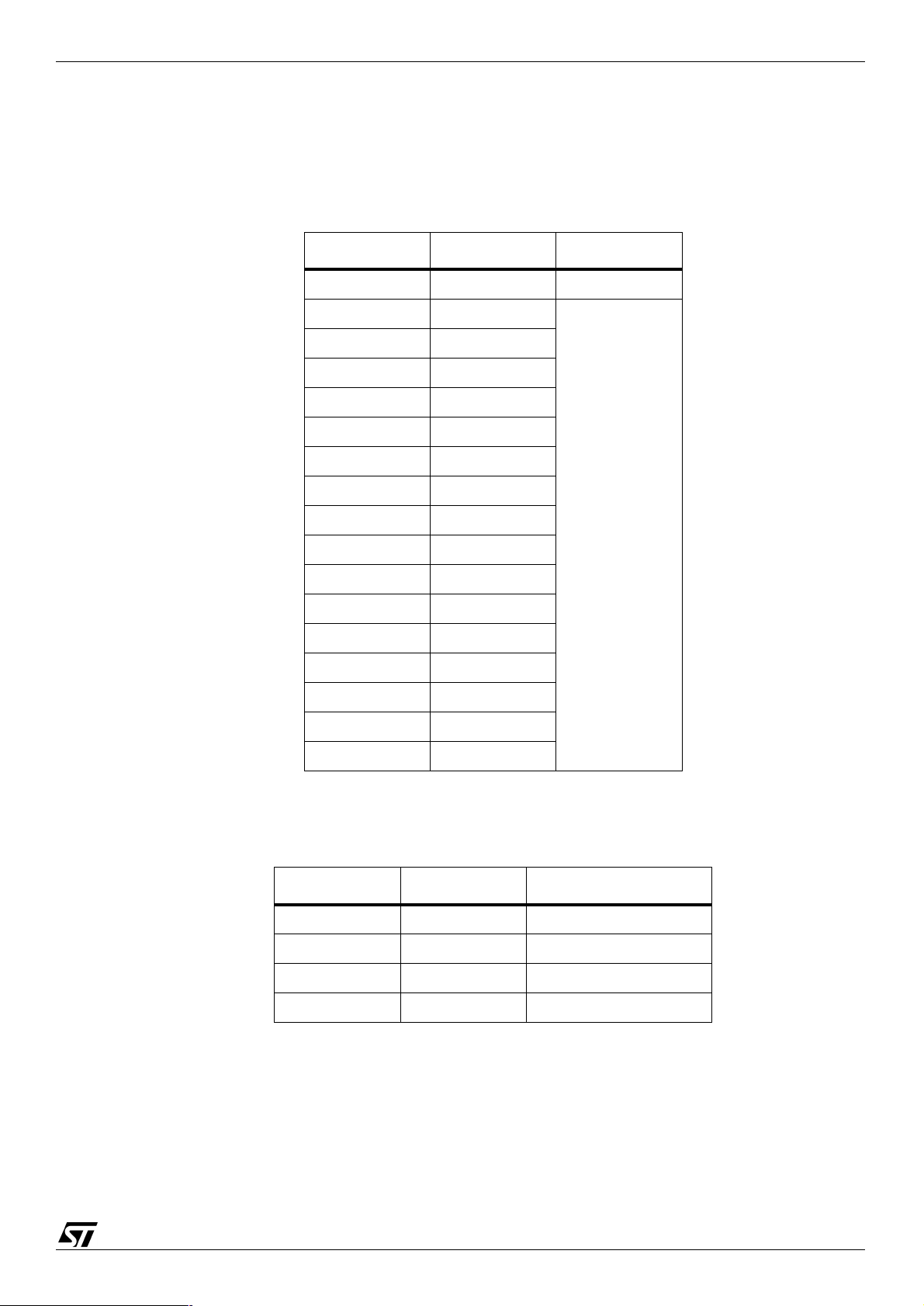
2.6 Memory
Region Usage Memory map used Region space available
3 Unused Not applicable 0x6600 0000 - 0x67FF FFFF
2 LCD Address 2 is used as the
1 SRAM 0x6200 0000 - 0x623F FFFF 0x6200 0000 - 0x62FF FFFF
0x6400 0000 - 0x65FF FFFF
LCD register address signal
0 Flash (boot bank) 0x6000 0000 - 0x603F FFFF 0x6000 0000 - 0x60FF FFFF
2.7 Power supplies
Power to the board is supplied using a lump in cord power supply prov iding 5 V to the board. All
other required voltages are provided by on-board voltage regulators or voltage convertors.
DATASHEET ADCS 7652091D STMicroelectr o nics 7/27
Table 1: STR710-EVAL board EMI memory map

2 Hardware STR710-EVAL board
2.8 USB full spe ed interface
USB full speed interface device supported by a type B connector. The USB clock uses a separate
48 MHz oscillator. See Section 3.1: USB on page 14.
2.9 CAN interface
A general purpose, asynchronous serial I/O data port connected through a 9-pin D-type male
connector with microswitch selectable low speed fault tolerant transceiver (L9669) or low or high
speed selectable transceiver (L9615 or L9616). See Section 3.2: CAN bus connector on page 14.
Caution: The board schemati c for the CAN interface detailed in Figure 16: CAN
interfac e on pa ge 21, is not a reference design and should not be copied. To
design a CAN interface with the STR710 please refer to the “STR71x
Hardware Develop m ent Getting Started Guide AN1 775”.
2.10 RS232 serial interfaces
Two general purpose, as ynchr ono us serial I/O da ta ports are conne cted th roug h 9-p in D-ty pe male
conne ctors r efer to Section 3.4: RS232 serial d ata connector on page 15.
RS232-A connects directly to UART0, transmit and rec eive only . RS232-B connects to either
UART1 or UART2 through switc h 9, transmit and receive only.
RTS is shorted to CTS and DTR is shorted to DSR at the connector for both interfaces.
2.11 External analog
An external analog input connector is provided, see Section 3.3: External analog on page 14 and
Figure 11: STR710-EVAL board to p-level page 1 of 2 on page 16.
2.12 Analog input
The analog input to ADC is demon strated by the variable resistor R63. Although there is a
thermistor connected up to the analogue input AIN.1 in the sche matics Figure 11: STR710-EVAL
board top-level page 1 of 2 on pa ge 16, it is not functional and has been remov ed from the pr oduct.
8/27 STMicroelectroni cs ADCS 7652091D DATASHEET
STR710-EVAL board 2 Hardware
2.13 LEDs
Software controlled LEDs
The LEDs in Table 2 are software controlled by PIO pins. See the s chematic in Figure 11 on
page 16.
LED Description Color
LD20 LED_P1_2 Red/Green
LD3 LED_PO_3 Red
LD4 LED_PO_2
LD5 LED_PO_1
LD6 LED_PO_0
LD8 LED_PO_12
LD9 LED_P1_15
LD10 LED_P2_9
Status LEDs
LD11 LED_P2_10
LD12 LED_P2_11
LD13 LED_P2_12
LD14 LED_P2_13
LD15 LED_P2_14
LD16 LED_P2_15
LD17 LED_P1_6
LD18 LED_P1_5
LD19 LED_P1_4
Table 2: Software controlled LEDs
LED Description Schematic
LD1 +5 V Figure12 on page 17
LD2 +3.3 V Figure12 on page 17
LD7 Vbus Figure15 on page 20
LD21 not STDBY Figure 11 on page 16
Table 3: Status LED s
DATASHEET ADCS 7652091D STMicroelectr o nics 9/27

2 Hardware STR710-EVAL board
2.14 Option jumper placement
SW10
J4
J3
SW9
SW15
Prototype area
SW13
SW14
STR710FZ2T6
ARM7TDMI
SW8
TM
SW7
SW5
J1
SW1
SW2
J5
SW11
WAKE
SW12
RST
NXT
SEL
Figure 3: Option jumpers, resistors and switches
10/27 STMicroelectronics ADCS 7652091D DATASHEET
SW6
SW3
SW4

STR710-EVAL board 2 Hardware
Jumper Figure Description Default
J1
J3
J4
J5
Figure 16 on pag e 21 CAN link: not fitted / fitted (default)
Figure 12 on pag e 17 VBKP supply: internal / board (default))
Figure 19 on pag e 24 notJRst / notReset link: connected / open (default)
Figure 12 on pag e 17 Not fitted.
Table 4: Option jumpers
Jumpers are fitted as shown in figure Figure 4:
Not fitted Do not fit F itted
Figure 4: Jumper positions
Fitted
Fitted
Not fitted
Do not fit
DATASHEET ADCS 7652091D STMicroelectr o nics 11/27

2 Hardware STR710-EVAL board
2.15 Option switch settings
Switch Schematic Description Default
SW1
SW2 ON
SW3
SW4
SW5
SW6
SW7
SW8
Figure16 on page 21 CAN transceiver select: L9669 / L9616 (default)
Note SW1 and SW2 must be changed together.
1 = L9669
A = L9616
Figure11 on page 16 LCD Select
Figure11 on page 16 LCD Next
Figure16 on page 21 L9616 ASC speed:
1-2 = pull down = high speed
2-3 = pul l up = low speed
Figure17 on page 22
Figure17 on page 22 SPI flash notHOLD:
Figure17 on page 22 SPI flash notW:
2
I
C EEPROM write control (notWC):
1-2 = pull down = enable writes to EEPROM
2-3 = pul l up = disable writes to E EPROM
1-2 = pull down = SPI flash in “hold mode”
2-3 = pull up = SPI flash in “normal mode”
1-2 = pull down = Write protect
2-3 = pull up = Write enabled
ON
PTM
PTM
2-3
2-3
2-3
2-3
SW9
SW10
SW11
SW12
SW13
SW14
SW15
Figure11 on page 16 RS232 source select:
1 = UART1 connected to RS232-B
A = UART2 connected to RS232-B
- Not fitted: do not fit
Figure11 on page 16 Wake up
Figure11 on page 16 Reset
Figure11 on page 16 Boot mode 1, see Table 6 on page 13.
Figure11 on page 16 Boot mode 0, see Table 6 on page 13.
Figure11 on page 16 Boot EN, see Table 6 on page 13.
Ta b le 5: Option switch settings
For swit ch position details see Figure 5: Switch positions on page 13.
1
PTM
PTM
2-3
1-2
2-3
12/27 STMicroelectronics ADCS 7652091D DATASHEET

STR710-EVAL board 2 Hardware
Boot
EN
(SW15)
Boot1
B1
(SW13)
Boot0
B0
(SW14)
Mode
Boot memory
mapping
Notes
1-2 any any USER flash mapped at 0h System executes code
2-3 1-2 1-2
2-3 1-2 2-3 BOOT BOOTFLASH
mapped at 0h
from flash
System executes a
“primary boot loader
(ST-firmware)” from
Boot-FLASH then jumps
to RAM
Clock FROZEN
2-3 2-3 1-2 RAM RAM mapped at 0h System executes code
from internal RAM
For Lab development
BOOT0
BOOT1
BOOTEN
BOOT0
BOOT1
BOOTEN
BOOT0
BOOT1
SW14
SW13
SW15
SW14
SW13
SW15
SW14
SW13
STR71
STR71
STR71
2-3 2-3 2-3 EXTMEM EXTMEM
mapped at oh
Table 6: Boot modes
1-2
2-3
Microswitc hes Slide swit ches
System executes code
from external memory
1A
1
A
BOOTEN
BOOT0
BOOT1
BOOTEN
1
A
SW15
SW14
SW13
SW15
STR71
Figure 5: Switch positions
DATASHEET ADCS 7652091D STMicroelectr o nics 13/27

3 Connectors STR710-EVAL board
3 Connectors
3.1 USB
USB-B
Figure 6: USB-B connector: CN3
Pin Description Pin Description Pin Description Pin Description
1 VBUS 2 DM 3 DP 4 GND
Table 7: USB-B connector pinout: CN3
3.2 CAN bus connector
Pin Description Pin Description Pin Description
1 Not connected 4 Not connected 7 CAN H, high side bus output
2 CAN L, low side bus output 5 Not connected 8 Pull down to GROUND
3 GROUND 6 GROUND 9 Pull up to +3.3 V
3.3 External analog
CAN - data
1
Figure 7: CAN connector 9 pin male D-type: CN1
Table 8: CAN connector pinout: CN1
5432
9876
External analog
1
Figure 8: External analog connector: CN6
Pin Description Pin Description
1 Analog input 2 Ground
Ta ble 9: External analog connector pinout: CN6
14/27 STMicroelectronics ADCS 7652091D DATASHEET
2

STR710-EVAL board 3 Connectors
3.4 RS232 serial data connector
9-pin general purpose D-ty pe male connectors
Pin Description Pin Description Pin Description
1 Shorted to pin 4 and 6 4 Shorted to pin 1 and 6 7 Shorted to pin 8
2 R1IN (port A), R2IN (port B) 5 GROUND 8 Shorted to pin 7
3 T1OUT (port A), T2OUT (port B) 6 Shorted to pin 1 and 4 9 Not connected
3.5 DEBUG
RS232 - Data A
1
5432
9876
RS232 - Data B
1
Figure 9: RS232 transmit and receive connectors: CN7, CN8
Table 10: RS232 connector pinout: CN7, CN8
Debug-JTAG port
13151719
11
123456789
5432
9876
1214161820
10
Figure 10: JTAG standard interface: CN9
Pin Description Pin Description Pin Description
4, 6, 8, 10,
12, 14, 16,
18, 20
1 VTref +3.3 V 7 TMS 15 noTReset
2 Vsupply +3.3 V 9 TCK 17 DBGRQS - pulled down
3 notTRST 11 RTCK (GROUND) 19 Pulled down
GROUND 5 TDI 13 TD0
Table 11: JTAG interface pino ut: CN9
DATASHEET ADCS 7652091D STMicroelectr o nics 15/27

4 Schematics STR710-EVAL board
4 Schematics
Figure 11: STR710-EVAL board top-level page 1 of 2
16/27 STMicroelectronics ADCS 7652091D DATASHEET

STR710-EVAL board 4 Schematics
DO NOT FIT
Figure 12: STR710-EVAL board top-level page 2 of 2
DATASHEET ADCS 7652091D STMicroelectr o nics 17/27

4 Schematics STR710-EVAL board
Figure 13: EMI flash
18/27 STMicroelectronics ADCS 7652091D DATASHEET

STR710-EVAL board 4 Schematics
Figure 14: EMI SRAM
DATASHEET ADCS 7652091D STMicroelectr o nics 19/27

4 Schematics STR710-EVAL board
Figure 15: USB interface
20/27 STMicroelectronics ADCS 7652091D DATASHEET

STR710-EVAL board 4 Schematics
Figure 16: CAN interface
DATASHEET ADCS 7652091D STMicroelectr o nics 21/27

4 Schematics STR710-EVAL board
Figure 17: Serial ROM interface
22/27 STMicroelectronics ADCS 7652091D DATASHEET

STR710-EVAL board 4 Schematics
Figure 18: RS232 Interface
DATASHEET ADCS 7652091D STMicroelectr o nics 23/27

4 Schematics STR710-EVAL board
Figure 19: ARM JTAG Interface
24/27 STMicroelectronics ADCS 7652091D DATASHEET

STR710-EVAL board 4 Schematics
Figure 20: LCD Interface
DATASHEET ADCS 7652091D STMicroelectr o nics 25/27

Revision history STR710-EVAL board
Revision history
Version Da te Comments
D September 05 Removed list of third party support vendors from description.
C September 05 Updated Section 2.9: CAN interface on page 8 to include caution.
Updated Chapter 4: Schematics to include the latest revision of schematics.
B March 05 Amended Section 1.2 on page 4 to list the JTAG connector CN9.
Amended Section 2.8 on page 8 to improve the USB interface description.
Amended Section 2.9 on page 8 to improve the CAN interface description.
Updated Table 4: Option jumpers on page 11 to show J5 is not fitted.
Amended the wording for SW1 in Table 5 on page 12.
Amended the first table entry in Table 11 on page 15.
Updated Chapter 4: Schematics:
Figure 11: STR710-EVAL board top-level page 1 of 2 on page 16:
C80 is now marked as “Do not fit”,
IC20 reset circuit has a threshold voltage of 3.07 V not 2.63 V.
Figure 12: STR710-EVAL board top-level page 2 of 2 on page 17 J5 marked as “Do not
fit”.
Figure 15: USB interface on page 20 IC2 shown with correct connectivity. Note that on
the PCB, IC2 is connected with In/Out swapped.
Figure 19: ARM JTAG Interface on page 24, R92 is now removed because it was in
parallel with R83.
A April 04 Initial release.
26/27 STMicroelectronics ADCS 7652091D DATASHEET

STR710-EVAL board
Information furnished is believed to be accurate and reliable. However, STMicroelectronics assumes no responsibility for the consequences
of use of such information nor for any infringement of patents or other rights of third parties which may result from its use. No license is granted
by implication or otherwise under any patent or patent rights of STMicroelectronics. Specifications mentioned in this publication are subject
to change without notice. This publication supersedes and replaces all information previously supplied. STMicroelectronics products are not
authorized for use as critical com ponents in life support devices or system s without the express written approval of STMicroelectronics.
The ST logo is a registered trademark of STMicroelectronics.
®
and ARM7TDMITM are registered trademarks of ARM Limited in the EU and other countries.
ARM
© 2004, 2005 STMicroele ctronics. All Rights Res erved.
STMicroelectronics Group of Companies
Australia - Belgium - Brazil - Canada - China - Czech Republic - Finland - France - Germany
Hong Kong - India - Israel - Italy - Japan - Malaysia - Malta - Morocco - Singapore - Spain - Sweden
Switzerland - United Kingdom - United States
www.st.com
27/27 STMicroelectronics ADCS 7652091D DATASHEET
 Loading...