ST STPSC1006 User Manual

STPSC1006

600 V power Schottky silicon carbide diode

Features

No or negligible reverse recovery

Switching behavior independent of temperature

Particularly suitable in PFC boost diode function

Description

The SiC diode is an ultrahigh performance power Schottky diode. It is manufactured using a silicon carbide substrate. The wide band gap material allows the design of a Schottky diode structure with a 600 V rating. Due to the Schottky construction no recovery is shown at turn-off and ringing patterns are negligible. The minimal capacitive turn-off behavior is independent of temperature.

ST SiC diodes will boost the performance of PFC operations in hard switching conditions.
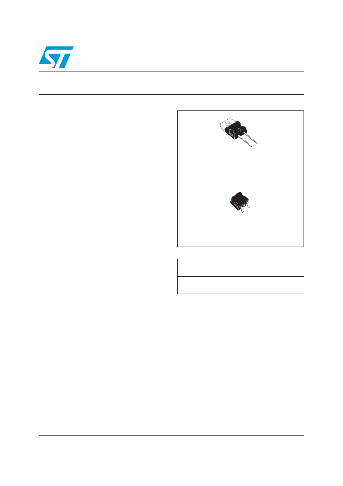
A

K


TO-220AC


STPSC1006D


K


A


NC


D2PAK


STPSC1006G


Table 1.

Device summary


IF(AV)


10 A


VRRM


600 V


Tj (max)


175 °C


QC (typ)


12 nC

November 2010

Doc ID 16287 Rev 3

1/8

www.st.com

Characteristics


STPSC1006


1

Characteristics


Table 2.


Absolute ratings (limiting values at 25 °C unless otherwise specified)


Symbol


Parameter


Value


Unit


VRRM

Repetitive peak reverse voltage


600


V


IF(RMS)

Forward rms current


18


A


IF(AV)

Average forward current


Tc = 115 °C, δ = 0.5


10


A


Surge non repetitive forward

tp = 10 ms sinusoidal, Tc = 25 °C

40


IFSM

tp = 10 ms sinusoidal, Tc = 125 °C

32


A


current


tp = 10 µs square, Tc = 25 °C

160


IFRM

Repetitive peak forward current

δ = 0.1, TC = 110 °C,


40


A


Tj = 150 °C


Tstg

Storage temperature range


-55 to +175


°C


Tj

Operating junction temperature


-40 to +175


°C


Table 3.


Thermal resistance


Symbol


Parameter


Value


Unit


Rth(j-c)


Junction to case


2


°C/W


Table 4.


Static electrical characteristics


Symbol


Parameter


Tests conditions


Min.


Typ.


Max.


Unit


I

(1)

Reverse leakage

Tj = 25 °C

V

R

= V

RRM

-


30


150


µA


current


R

Tj = 150 °C


-


210


1500


V

(2)

Forward voltage drop

Tj = 25 °C

I


= 10 A


-


1.4


1.7


V


F


F


Tj = 150 °C


-


1.6


2.1


1. tp = 10 ms, δ < 2%


2. tp = 500 µs, δ < 2%


To evaluate the conduction losses use the following equation:


P = 1.2 x IF(AV) + 0.09 x IF2(RMS)


Table 5.


Other parameters


Symbol


Parameter


Test conditions


Typ.


Unit


Qc


Total capacitive charge


Vr = 400 V, IF = 10 A

dIF/dt = -200 A/µs


12


nC


Tj = 150 °C


C


Total capacitance


Vr = 0 V, Tc = 25 °C, F = 1 Mhz


650


pF


Vr = 400 V, Tc = 25 °C, F = 1 Mhz


50


2/8

Doc ID 16287 Rev 3

ST STPSC1006 User Manual

STPSC1006

Characteristics


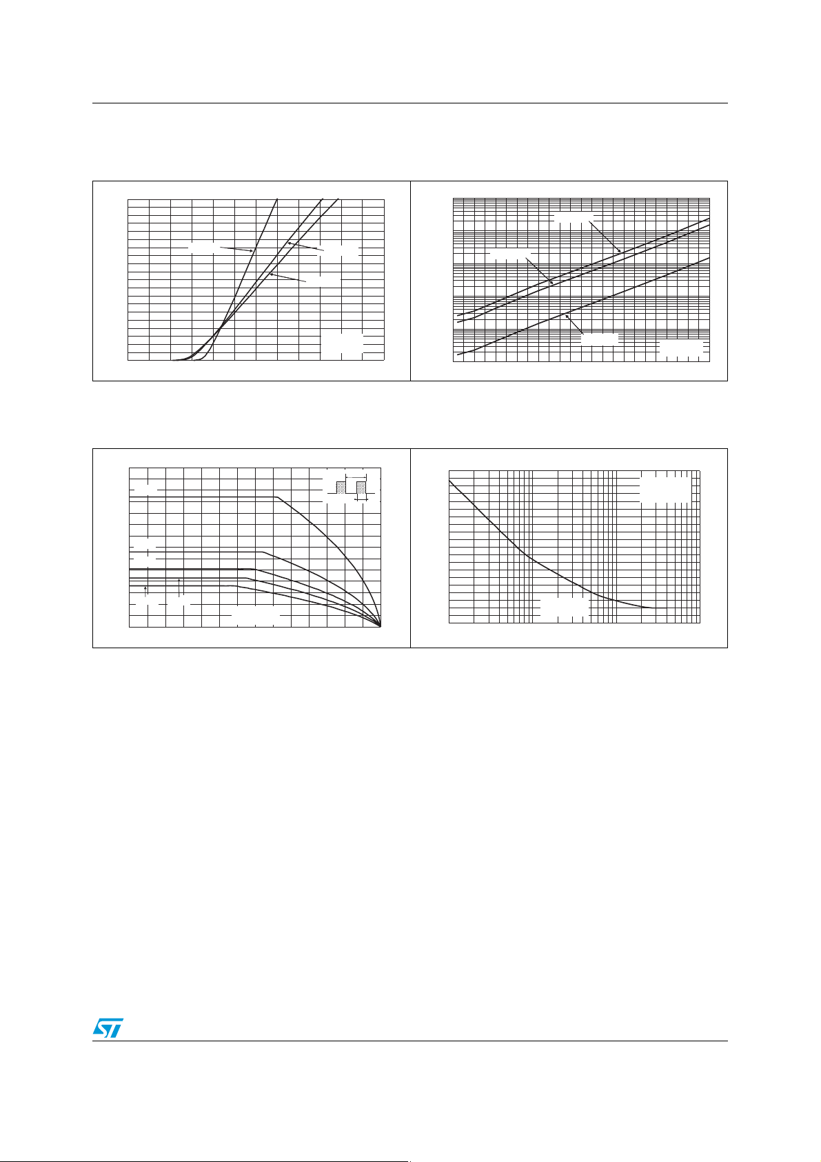
Figure 1. Forward voltage drop versus

Figure 2. Reverse leakage current versus

forward current (typical values)

reverse voltage applied


(maximum values)

I

(A)


I

(µA)


FM


1.E+04

R


20


18


Tj=175 °C


16


1.E+03


14


Tj=25 °C


Tj=150 °C


Tj=150 °C


1.E+02


12


10


Tj=175 °C


8


1.E+01


6


4


1.E+00


2


VFM(V)


Tj=25 °C


VR(V)


0


1.E-01


0.0


0.5

1.0

1.5

2.0

2.5

3.0


0

50

100

150

200

250

300

350

400

450

500

550

600

Figure 3. Peak forward current versus case Figure temperature

4.Junction capacitance versus reverse voltage applied (typical values)

I

(A)

M


70


T

60

δ=0.1


δ=tp/T

tp

50

40

δ=0.3

30 δ=0.5

20

10 δ=1 δ=0.7

TC(°C)

0

0

25

50

75

100

125

150

175

C(pF)


500


450


F=1 MHz


VOSC=30 mVRMS


400


Tj=25 °C


350


300


250


200


150


100


50


VR(V)


0


1

10

100

1000

Doc ID 16287 Rev 3

3/8

Loading...
+ 5 hidden pages