

Features
STPS30SM60
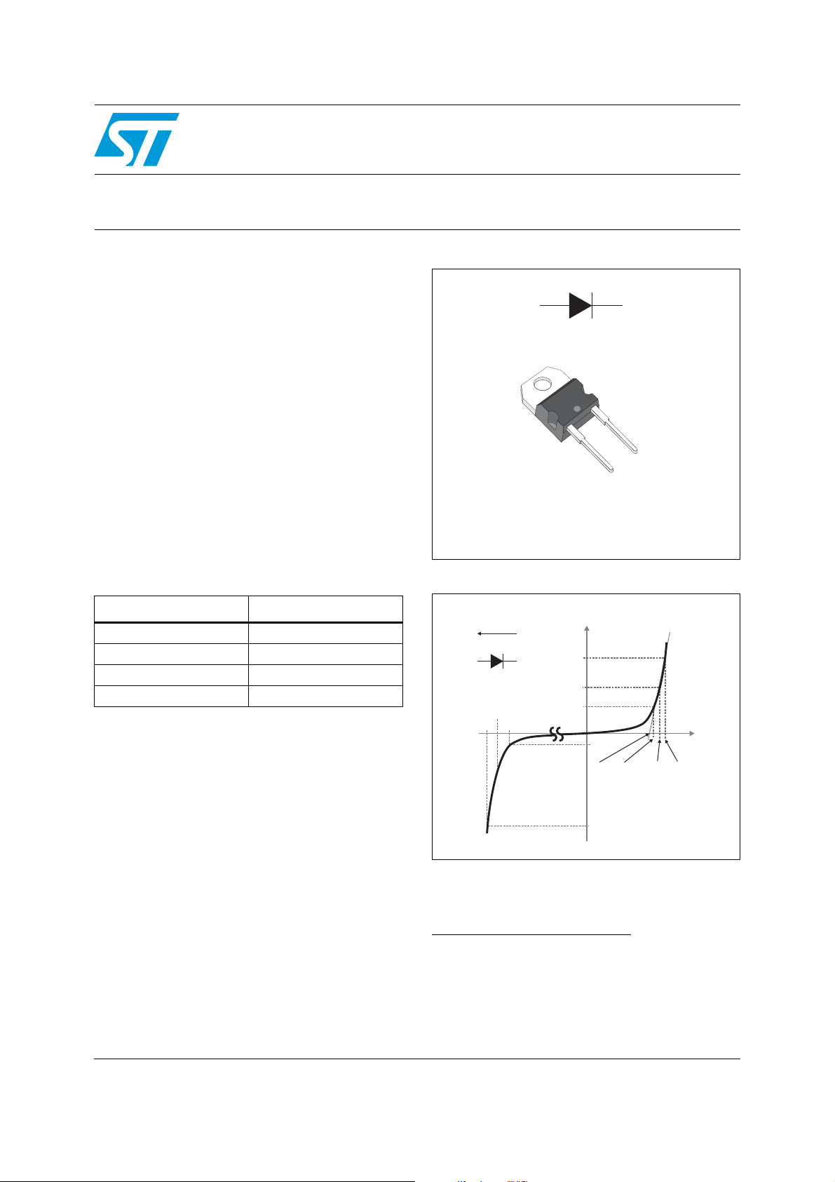
Power Schottky rectifier
■ High current capability
■ Avalanche rated
■ Low forward voltage drop
■ High frequency operation
Description
The STPS30SM60D is a single diode Schottky
rectifier, suited for high frequency switch mode
power supply.
Packaged in TO-220AC,this device is intended to
be used in notebook, game station and desktop
adapters, providing in these aplications a good
efficiency at both low and high load.
Table 1. Device summary
Symbol Value
I
F(AV)
V
RRM
(typ) 0.410 V
V
F
(max) 150 °C
T
j
30 A
60 V
A
K
K
A
K
TO-220AC
STPS30SM60D
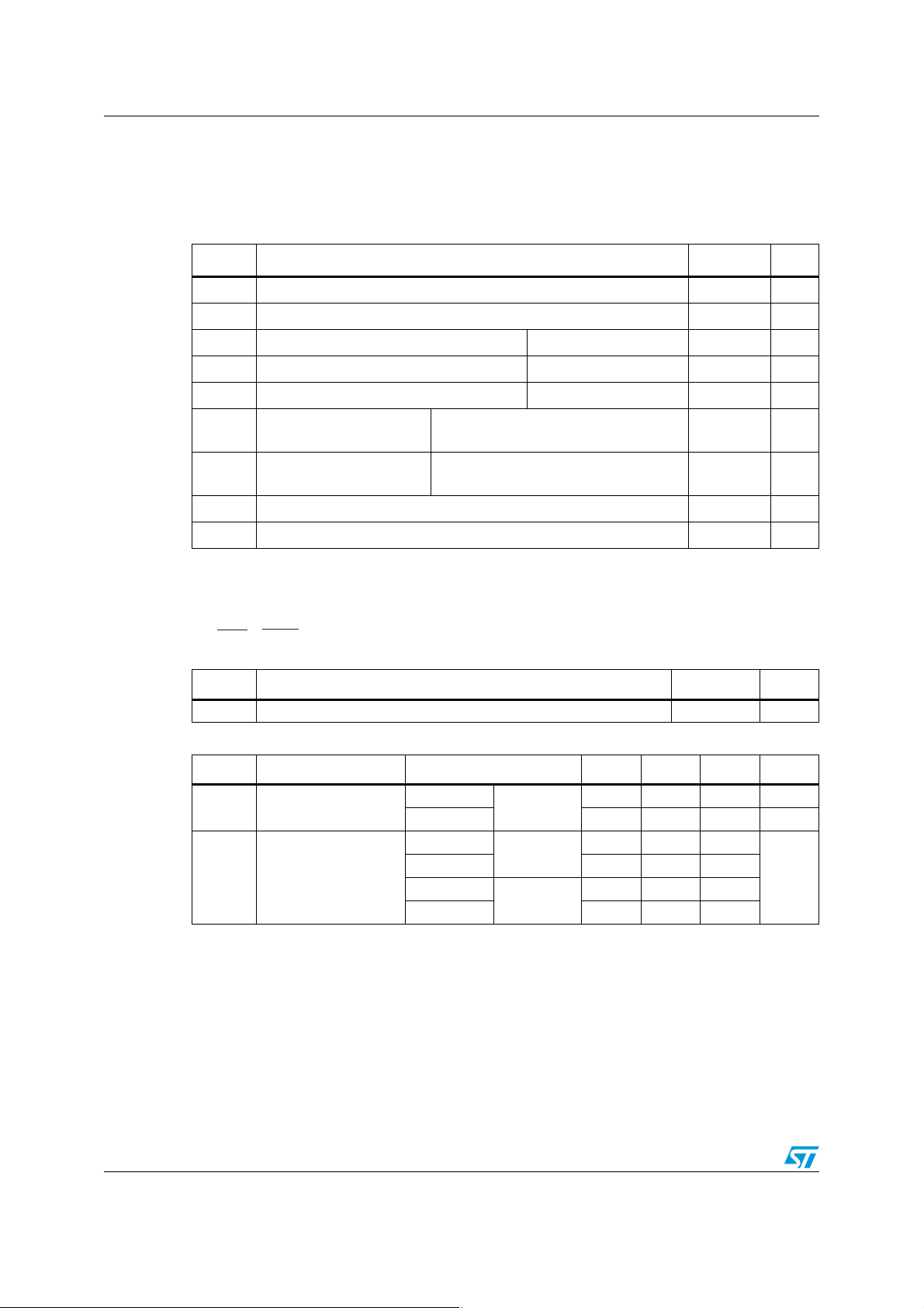
Figure 1. Electrical characteristics
2 x I
I
"Forward"
F(Io)
X
X
V
F
O
I
F
I
O
I
R
V
V
To
V
I
V
RRM
V
V
AR
R
"Reverse"
(a)
V
F(2xIo)
V
I
AR
a. V
and I
ARM
operating area defined in Figure 11. V
pulse measurements (t
are static characteristics
must respect the reverse safe
ARM
< 1 µs). VR, IR, V
p
and IAR are
AR
and VF,
RRM
October 2011 Doc ID 022053 Rev 1 1/7
www.st.com
7
Characteristics STPS30SM60
1 Characteristics
Table 2. Absolute ratings (limiting values, at T
specified)
Symbol Parameter Value Unit
= 25 °C unless otherwise
amb
V
I
F(RMS)
I
F(AV)
I
P
ARM
V
ARM
V
ASM
T
1. For temperature or pulse time duration deratings, please refer to Figure 4 and 5. More details regarding the
2. See Figure 11
3. condition to avoid thermal runaway for a diode on its own heatsink
Table 3. Thermal parameters
Repetitive peak reverse voltage 60 V
RRM
Forward rms current 60 A
Average forward current, δ = 0.5 Tc = 125 °C 30 A
Surge non repetitive forward current tp = 10 ms sine-wave 400 A
FSM
(1)
Repetitive peak avalanche power Tj = 25 °C, tp = 1 µs 28000 W
Maximum repetitive peak
(2)
avalanche voltage
Maximum repetitive peak
(2)
avalanche voltage
Storage temperature range -65 to +175 °C
stg
Maximum operating junction temperature
T
j
avalanche energy measurements and diode validation in the avalanche are provided in the application
notes AN1768 and AN2025.
<
Rth(j-a)
1
dPtot
dTj
t
< 1 µs, Tj < 150 °C, IAR < 105 A 80 V
p
< 1 µs, Tj < 150 °C, IAR < 105 A 80 V
t
p
(3)
150 °C
Symbol Parameter Value Unit
th(j-c)
Junction to case 1.0 °C/W
R
Table 4. Static electrical characteristics
Symbol Parameter Test conditions Min. Typ. Max. Unit
T
Reverse leakage
(1)
I
R
current
(2)
V
1. Pulse test: tp = 5 ms, δ < 2 %
2. Pulse test: tp = 380 µs, δ < 2 %
Forward voltage drop
F
= 25 °C
j
= 125 °C - 20 80 mA
T
j
Tj = 25 °C
= 125 °C - 0.410 0.470
T
j
= 25 °C
T
j
= 125 °C - 0.515 0.600
T
j
V
= V
R
I
= 15 A
F
I
= 30 A
F
RRM
- 30 135 µA
- 0.500 0.540
- 0.570 0.640
V
To evaluate the conduction losses use the following equation:
P = 0.435 x I
2/7 Doc ID 022053 Rev 1
+ 0.0055 x I
F(AV)
F2(RMS)

STPS30SM60 Characteristics
Figure 2. Average forward power dissipation
versus average forward current
P (W)
F(AV)
28
24
20
16
12
8
4
0
0 4 8 1216202428323640
δ = 0.05
δ = 0.1
δ = 0.2
δ = t / T
p
δ = 0.5
T
t
p
δ = 1
I (A)
F(AV)
Figure 4. Normalized avalanche power
derating versus pulse duration
P(tp)
ARM
P (1µs)
ARM
1
0.1
Figure 3. Average forward current versus
ambient temperature (δ = 0.5)
I (A)
F(AV)
35
R
= R
th(j-a)
30
25
20
15
10
5
0
0 25 50 75 100 125 150
th(j-c)
T (°C)
amb
Figure 5. Normalized avalanche power
derating versus junction
temperature
P(T)
ARM j
P (25 °C)
ARM
1.2
1
0.8
0.01
t (µs)
0.001
0.10.01 1
10 100
p
1000
Figure 6. Non repetitive surge peak forward
current versus overload duration
(maximum values)
I (A)
M
350
300
250
200
150
100
I
M
50
0
1.E-03 1.E-02 1.E-01 1.E+00
t
δ = 0.5
T = 25 °C
c
T = 75 °C
c
T = 125 °C
c
t(s)
0.6
0.4
0.2
0
25 50 75 100 125
Figure 7. Relative thermal impedance
junction to case versus pulse
duration
Z/R
th(j-c) th(j-c)
1.0
0.9
0.8
0.7
0.6
0.5
0.4
0.3
Single pulse
0.2
0.1
0.0
1.E-04 1.E-03 1.E-02 1.E-01 1.E+00
T (°C)
t (s)
p
j
150
Doc ID 022053 Rev 1 3/7
 Loading...