

ST STPS0520Z User Manual
®
MAIN PRODUCT CHARACTERISTICS
STPS0520Z
SCHOTTKY RECTIFIERS
I
F(AV)
V
RRM
V
(max) 0.32 V
F
0.5 A
20 V
FEATURES AND BENEFITS
VERY SMALL CONDUCTION LOSSES
■
NEGLIGIBLE SWITCHING LOSSES
■
EXTREMELY FAST SWITCHING
■
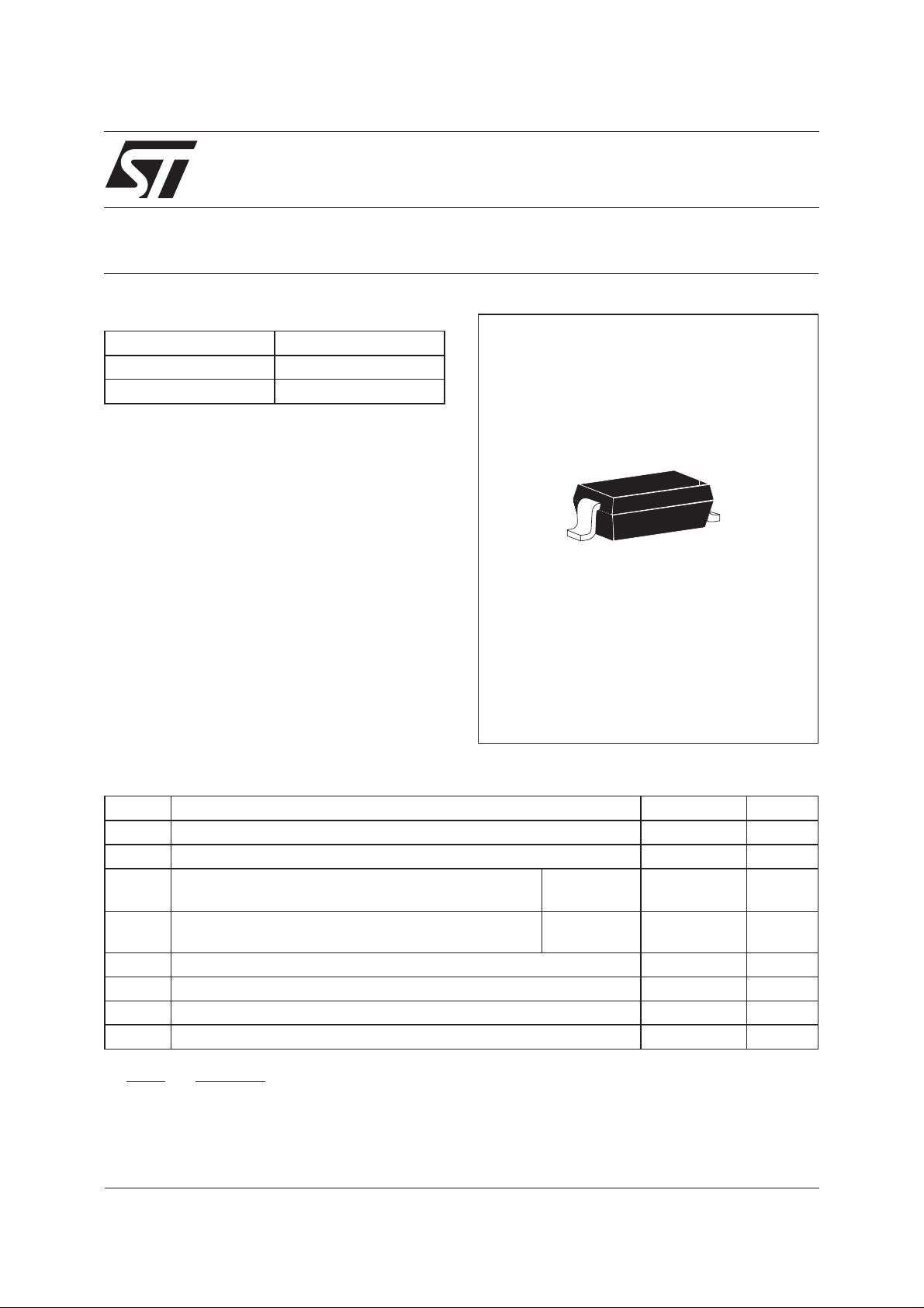
DESCRIPTION
Single Schottky rectifier suited for switch mode
power supplies and high frequency DC to DC
converters.
Packaged in SOD-123, this device is intended for
use in low voltage, high frequency inverters, free
wheeling and polarity protection applications. Due
to the small size of the package this device fits
GSM and PCMCIA requirements.
ABSOLUTE RATINGS (limiting values)
SOD-123
Symbol Parameter Value Unit
V
RRM
I
F(RMS)
I
F(AV)
Repetitive peak reverse voltage 20 V
RMS forward current 2 A
Average forward current
Ta=25°C 0.5 A
δ=0.5
I
FSM
Surge non repetitive forward current tp=10ms
5.5 A
sinusoidal
dV/dt Critical rate of rise of reverse voltage 10000 V/µs
T
Storage temperature range - 65 to + 125 °C
stg
Tj Maximum operating junction temperature * 125 °C
TL Maximum temperature for soldering during 10s 260 °C
dPtot
*:
<
dTj Rth j a
January 2002 - Ed : 2B
thermal runaway condition for a diode on its own heatsink
−1()
1/5
STPS0520Z
THERMAL RESISTANCE
Symbol Parameter Value Unit
R
th (j-a)
Junction to ambient 430 (*)
210 (**)
(*) Mountedonepoxy board with recommended Pad Layout.
(**) Mounted on epoxy board with 50mm2 copper area.
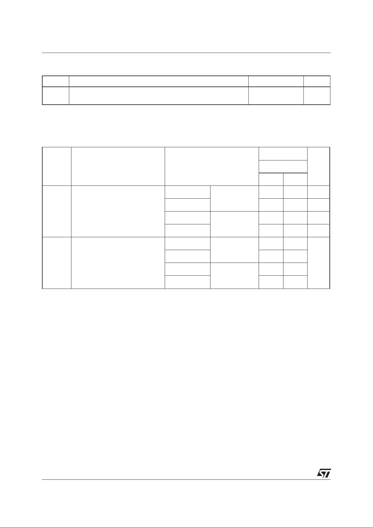
STATIC ELECTRICAL CHARACTERISTICS
Value
Symbol Parameter Tests conditions
typ. max.
I
* Reverseleakage current Tj = 25°C VR=10V 60 µA
R
Tj = 100°C 2.5 5 mA
Tj = 25°C V
R=VRRM
Tj = 100°C 4.3 8 mA
V
** Forwardvoltage drop Tj = 25°C IF= 0.1 A 0.3 V
F
Tj = 100°C 0.18 0.22
Tj = 25°C I
= 0.5 A 0.385
F
°C/W
UnitSTPS0520Z
150 µA
Tj=100°C 0.29 0.32
Pulse test : * tp=5ms,δ<2%
** tp = 380 µs, δ <2%
To evaluate the maximum conduction losses use the following equation :
P=0.23xI
F(AV)
+0.18xI
F2(RMS)
2/5
 Loading...