

ST STP08C596 User Manual
STP08C596
STP08C596
8-BIT CONSTANT CURRENT LED SINK DRIVER
■8 CONSTANT CURRENT OUTPUT CHANNELS
■ADJUSTABLE OUTPUT CURRENT THROUGH EXTERNAL RESISTOR
■SERIAL DATA IN/PARALLEL DATA OUT
■SERIAL OUT CHANGE STATE ON THE FAILING EDGES OF CLOCK
■OUTPUT CURRENT: 15-120 mA
■25 MHz CLOCK FREQ.
■AVAILABLE IN HIGH THERMAL TSSOP EXPOSED PAD
■EFFICIENCY PACKAGE
DESCRIPTION
The STP08C596 is a monolithic, medium-voltage, low current power 8-bit shift register designed for LED panel display. The STP08C596 contains a 8-bit serial-in, parallel-out shift register that feeds a 8-bitD-type storage register. In the output stage, sixteen regulated current sources were designed to provide 15-120mA constant current to drive the LEDs.
Compared with the STPIC6C595, the device provides great flexibility and improved performance in LED panel system design.
Table 1: Order Codes
DIP-16 |
SO-16 |
TSSOP16
Trough an external resistor, users may adjust the STP08C596 output current, controlling in this way the light intensity of LEDs.
The STP08C596 guarantees 16V output driving capability, allowing users to connect more LEDs in series. The high clock frequency, 25 MHz, also satisfies the system requirement of high volume data transmission.
Part Number |
Temp. Range |
Package |
Comments |
|
|
|
|
STP08C596B1 |
-40°C to 125°C |
DIP-16 |
25 part per tube |
|
|
|
|
STP08C596M |
-40°C to 125°C |
SO-16 (Tube) |
50 parts per tube |
|
|
|
|
STP08C596MTR |
-40°C to 125°C |
SO-16 (Tape & Reel) |
1000 parts per reel |
|
|
|
|
STP08C596TTR |
-40°C to 125°C |
TSSOP16 (Tape & Reel) |
2500 parts per reel |
February 2005 |
Rev. 7 |
1/16 |
|
|
|

STP08C596
Table 2: Current Accuracy
Output Voltage |
|
Current accuracy |
Output Current |
|
|
|
|
||
Between bits |
|
Between ICs |
||
|
|
|
||
|
|
|
|
|
≥ 0.7V |
TYP. ± 3% |
|
± 10% |
15 to 120 mA |
|
|
|
|
|
Figure 1: Pin Connection
Table 3: Pin Description
PIN N° |
Symbol |
Name and Function |
|
|
|
1 |
GND |
Ground Terminal |
|
|
|
2 |
SDI |
Serial data input terminal |
|
|
|
3 |
CLK |
Clock input terminal |
|
|
|
4 |
/LE |
Latch input terminal |
|
|
|
5-12 |
OUT 0-7 |
Output terminal |
13 |
/OE |
Output enable input terminal (active low) |
|
|
|
14 |
SDO |
Serial data out terminal |
|
|
|
15 |
R-EXT |
Constant Current programming |
|
|
|
16 |
VDD |
5V Supply voltage terminal |
Table 4: Absolute Maximum Ratings |
||
Symbol |
Parameter |
Value |
Unit |
|
|
|
|
VDD |
Supply Voltage |
0 to 7 |
V |
VO |
Output Voltage |
-0.5 to 16 |
V |
IO |
Output Current |
120 |
mA |
VI |
Input Voltage |
-0.4 to VDD+0.4 |
V |
IGND |
GND Terminal Current |
980 |
mA |
fCLK |
Clock Frequency |
25 |
MHz |
TOPR |
Operating Temperature Range |
-40 to +125 |
°C |
TSTG |
Storage Temperature Range |
-55 to +150 |
°C |
Absolute Maximum Ratings are those values beyond which damage to the device may occur. Functional operation under these condition is not implied.
2/16

STP08C596
Table 5: Thermal Data
Symbol |
Parameter |
DIP-16 |
SO-16 |
TSSOP16 |
Unit |
|
|
|
|
|
|
Rthj-amb |
Thermal Resistance Junction-ambient |
90 |
125 |
140 |
°C/W |
Table 6: Recommended Operating Conditions
Symbol |
Parameter |
Test Conditions |
Min. |
Typ. |
Max. |
Unit |
|
|
|
|
|
|
|
VDD |
Supply Voltage |
|
4.5 |
5.0 |
5.5 |
V |
VO |
Output Voltage |
|
|
|
16.0 |
V |
IO |
Output Current |
OUTn |
15 |
|
120 |
mA |
IOH |
Output Current |
SERIAL-OUT |
|
|
+1 |
mA |
IOL |
Output Current |
SERIAL-OUT |
|
|
-1 |
mA |
VIH |
Input Voltage |
|
0.7VDD |
|
VDD+0.3 |
V |
VIL |
Input Voltage |
|
-0.3 |
|
0.3VDD |
V |
twLAT |
/LE Pulse Width |
VDD = 3.0 to 3.6V |
20 |
|
|
ns |
twCLK |
CLK Pulse Width |
|
20 |
|
|
ns |
twEN |
/OE Pulse Width |
|
400 |
|
|
ns |
tSETUP(D) |
Setup Time for DATA |
|
20 |
|
|
ns |
tHOLD(D) |
Hold Time for DATA |
|
15 |
|
|
ns |
tSETUP(L) |
Setup Time for LATCH |
|
15 |
|
|
ns |
fCLK |
Clock Frequency |
Cascade Operation |
|
|
25 |
MHz |
Table 7: Electrical Characteristics (VDD=5V, T = 25°C, unless otherwise specified.)
Symbol |
Parameter |
Test Conditions |
Min. |
Typ. |
Max. |
Unit |
||
|
|
|
|
|
|
|
|
|
VIH |
Input Voltage High Level |
|
|
|
0.7VDD |
|
VDD |
V |
VIL |
Input Voltage Low Level |
|
|
|
GND |
|
0.3VDD |
V |
IOH |
Output Leakage Current |
VOH = 16 V |
|
|
|
10 |
µA |
|
VOL |
Output Voltage (Serial-OUT) |
IOL = 1mA |
|
|
|
0.4 |
V |
|
VOH |
Output Voltage (Serial-OUT) |
IOH = -1mA |
|
VDD-0.4V |
|
|
V |
|
IOL1 |
Output Current |
VO = 0.7V |
REXT = 910 Ω |
20.6 |
20.7 |
20.9 |
mA |
|
IOL2 |
|
VO = 0.7V |
REXT = 360 Ω |
50.6 |
51.0 |
51.5 |
mA |
|
∆IOL1 |
Output Current Error |
VO = 0.7V |
REXT = 910 Ω |
|
|
± 3 |
% |
|
|
between bit (All Output ON) |
|
|
|
|
|
|
|
∆IOL2 |
VO = 0.7V |
REXT = 360 Ω |
|
|
± 3 |
% |
||
|
|
|
||||||
RSIN(up) |
Pull-up Resistor |
|
|
|
150 |
300 |
600 |
KΩ |
RSIN(down) |
Pull-down Resistor |
|
|
|
100 |
200 |
400 |
KΩ |
IDD(OFF1) |
Supply Current (OFF) |
REXT = OPEN |
OUT 0 to 7 = OFF |
|
0.3 |
0.6 |
mA |
|
IDD(OFF2) |
|
REXT = 470 Ω OUT 0 to 7 = OFF |
|
5.5 |
7.7 |
|
||
IDD(OFF3) |
|
REXT = 250 Ω OUT 0 to 7 = OFF |
|
10.1 |
14.1 |
|
||
IDD(ON1) |
Supply Current (ON) |
REXT = 470 Ω |
OUT 0 to 7 = ON |
|
5.5 |
7.7 |
|
|
IDD(ON2) |
|
REXT = 250 Ω OUT 0 to 7 = ON |
|
10.1 |
14.1 |
|
||
3/16
STP08C596
Table 8: Switching Characteristics (VDD=5V, T = 25°C, unless otherwise specified.)
Symbol |
|
|
|
Parameter |
Test Conditions |
Min. |
Typ. |
Max. |
Unit |
|
|
|
|
|
|
|
|
|
|||
tPLH1 |
Propagation Delay Time, |
VDD = 5 V |
VIH = VDD |
|
200 |
280 |
ns |
|||
|
CLK-OUTn, /LE = H, /OE = L |
VIL = GND |
CL = 13pF |
|
|
|
|
|||
tPLH2 |
|
Propagation Delay Time, |
|
160 |
250 |
ns |
||||
|
IO = 40mA |
VL = 3 V |
|
|||||||
|
|
|
|
|||||||
/LE-OUTn, /OE = L |
|
|
|
|
||||||
|
|
|
|
|
||||||
|
|
|
|
|
|
|
|
|
|
|
tPLH3 |
|
Prop |
agation Delay Time, |
REXT = 470 Ω |
RL = 65 Ω |
|
145 |
200 |
ns |
|
/OE-OUTn, /LE = H |
|
|
|
|
||||||
|
|
|
|
|
|
|
||||
|
|
|
|
|
|
|
|
|||
tPLH |
Propagation Delay Time, |
|
|
|
15 |
30 |
ns |
|||
|
CLK-SDO |
|
|
|
|
|
|
|||
tPHL1 |
Propagation Delay Time, |
|
|
|
15 |
30 |
ns |
|||
|
CLK-OUTn, /LE = H, /OE = L |
|
|
|
|
|
|
|||
tPHL2 |
|
Propagation Delay Time, |
|
|
|
15 |
30 |
ns |
||
|
|
|
|
|
||||||
/LE-OUTn, /OE = L |
|
|
|
|
|
|
||||
|
|
|
|
|
|
|
||||
|
|
|
|
|
|
|
|
|
|
|
tPHL3 |
|
Prop |
agation Delay Time, |
|
|
|
45 |
60 |
ns |
|
/OE-OUTn, /LE = H |
|
|
|
|
|
|
||||
|
|
|
|
|
|
|
||||
|
|
|
|
|
|
|
|
|||
tPHL |
Propagation Delay Time, |
|
|
|
15 |
300 |
ns |
|||
|
CLK-SDO |
|
|
|
|
|
|
|||
tr |
Output Rise Time |
|
|
|
160 |
200 |
ns |
|||
tf |
Output Fall Time |
|
|
|
15 |
25 |
ns |
|||
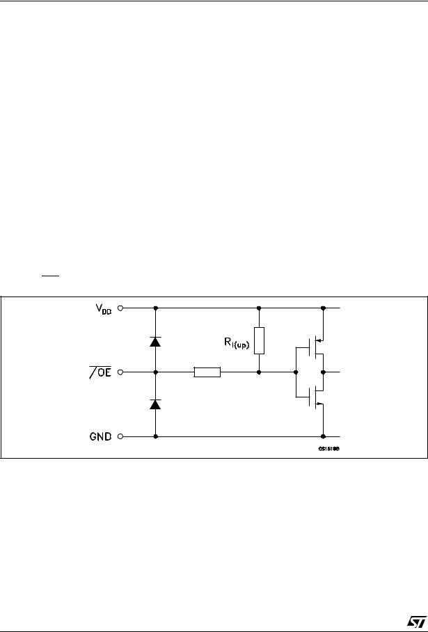
EQUIVALENT CIRCUIT OF INPUTS AND OUTPUTS
Figure 2: /OE Terminal
4/16

STP08C596
Figure 3: /LE Terminal
Figure 4: CLK, SDI Terminal
Figure 5: SDO Terminal
5/16
 Loading...