How it Works
Log In / Sign Up
Buy Points
How it Works
FAQ
Contact Us
Questions and Suggestions
Users
ST
Loading...
S
STGP12NB60K
STGP12NB60KD
STGP14NC60KD
STGP20NB37LZ
STGP20NB60K
STGP20NC60V
STGP3NB60F
STGP3NB60FD
STGP3NB60H
STGP3NB60HD
STGP3NB60HDFP
STGP3NB60K
STGP3NB60KD
STGP3NB60KDFP
STGP3NB60M
STGP3NB60MD
STGP6NC60HD
STGP7NB120SD
STGP7NB60F
STGP7NB60FD
STGP7NB60H
STGP7NB60HD
STGP7NB60HDFP
STGP7NB60K
STGP7NB60KD
STGP7NB60KDFP
STGP7NB60KFP
STGP7NB60M
STGP7NC60H
STGP7NC60HD
STGW12NB60H
STGW12NB60HD
STGW20NB60H
STGW20NB60HD
STGW20NB60KD
STGW20NC60V
STGW20NC60VD
STGW30N90D
STGW30NB60H
STGW30NB60HD
STGW30NC60W
STGW39NC60VD
STGW50NB60H
STGW50NB60M
STGY40NC60VD
STGY50NB60HD
STHDLS101
STHDLS101A
STHDLS101T
STHDMI002A
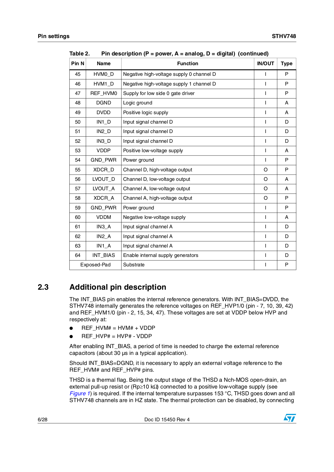
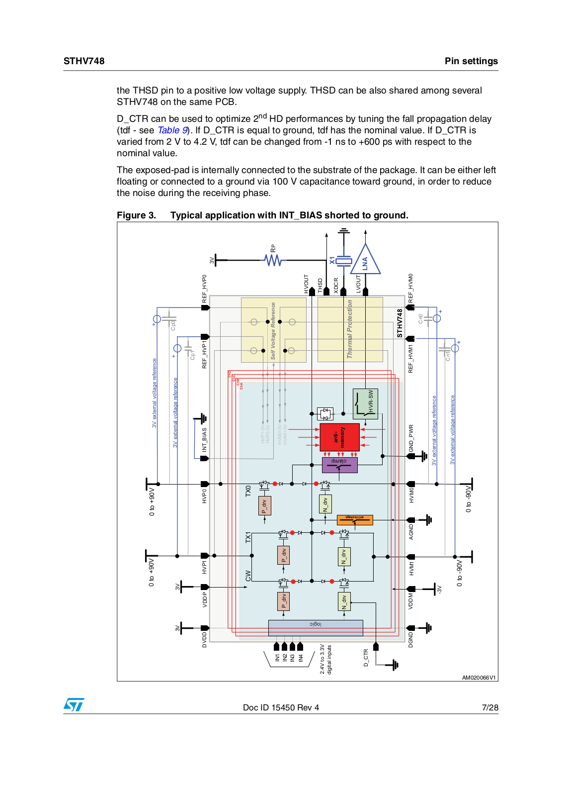
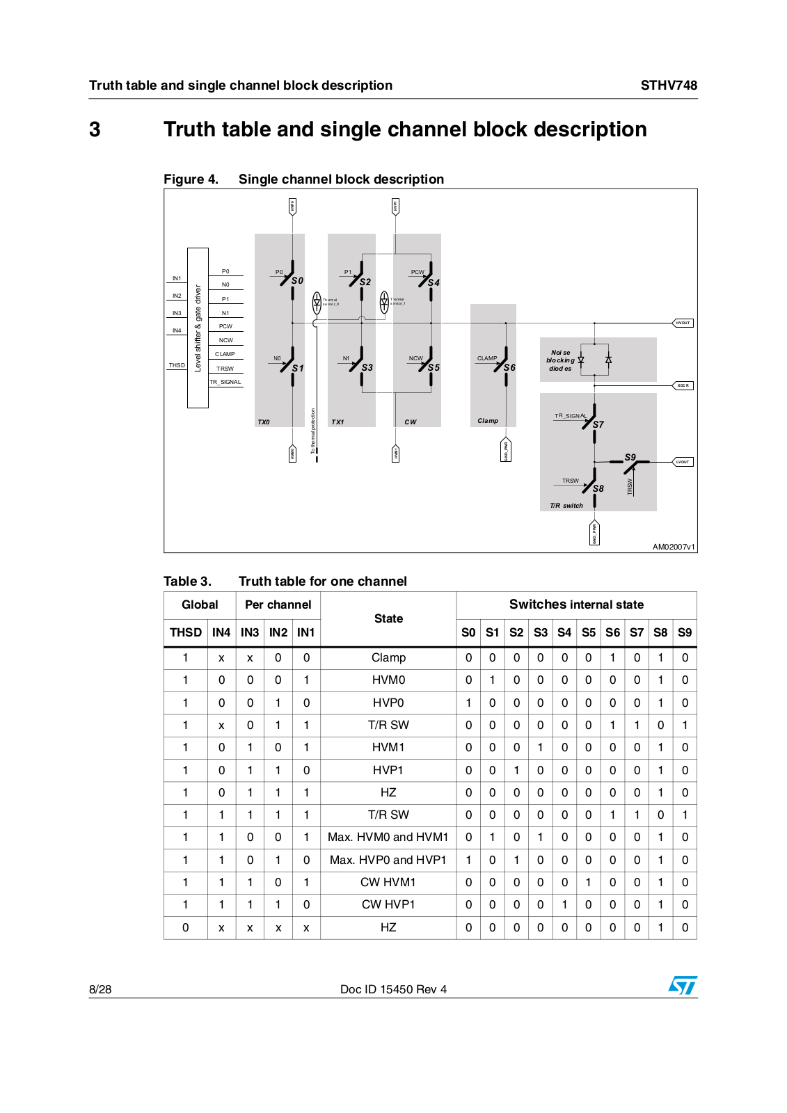
STHV748
STi3220
STi5100
STi5105
STi5107
STi5118
STi5167
STi5188
STi5197
STi5197L
STi5200
STi5202
STi5205
STi5206
STi5211
STi5251
STi5262
STi5289
STi5514
STi5517
STi7100
STi7101
STi7102
STi7105
STi7106
STi7108
STi7108M
STi7109
STi7110FTA
STi7111
STi7141
STi7162
STi7167
STi7197
STi7200
STi7710
STiH207
STiH223
STiH225
STiH237
STiH239
STiH251
STiH273
STiH416
STL8NH3LL
STLA01
STLA02
STLC1510
STLC2150
STLC2410B
Loading...
Loading...
Nothing found
STHV748
User Manual
28 pgs
678.01 Kb
0
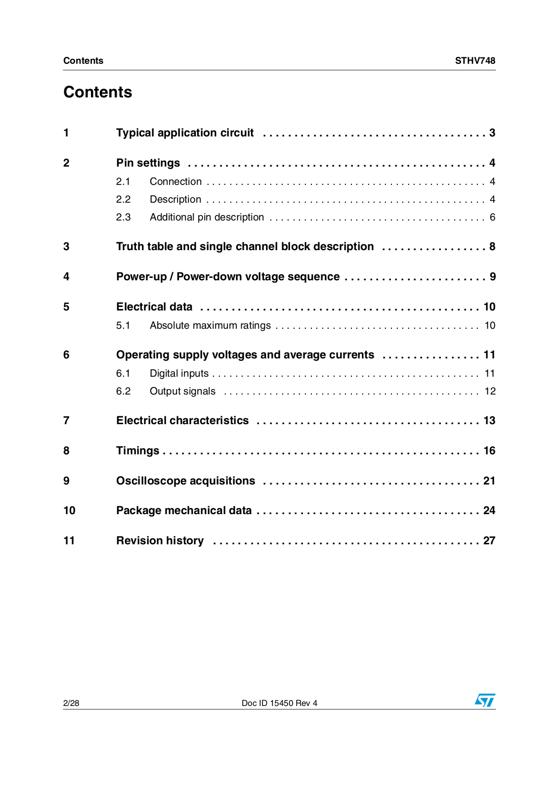
Table of contents
Loading...
ST STHV748 User Manual
...
ST User Manual
Download
Specifications and Main Features
Frequently Asked Questions
User Manual
Download
Loading...
+
19
hidden pages
Unhide
You need points to download manuals.
1 point = 1 manual.
You can buy points or you can get point for every manual you upload.
Buy points
Upload your manuals
 Loading...