

ST STGW30N90D User Manual
查询STGW30N90D供应商
Features
V
cesat
CE(sat)
@25°C
)
Type V
STGW30N90D 900V < 2.75V 30A
■ Low on-losses
■ Low on-voltage drop (V
■ High current capability
■ High input impedance (voltage driven)
■ Low gate charge
■ Ideal for soft switching application
CES
I
C
@100°C
STGW30N90D
N-channel 900V - 30A - TO-247
Very fast PowerMESH™ IGBT
Preliminary Data
TO-247
Description
Using the latest high voltage technology based on
its patented strip layout, STMicroelectronics has
designed an advanced family of IGBTs, with
outstanding performances.
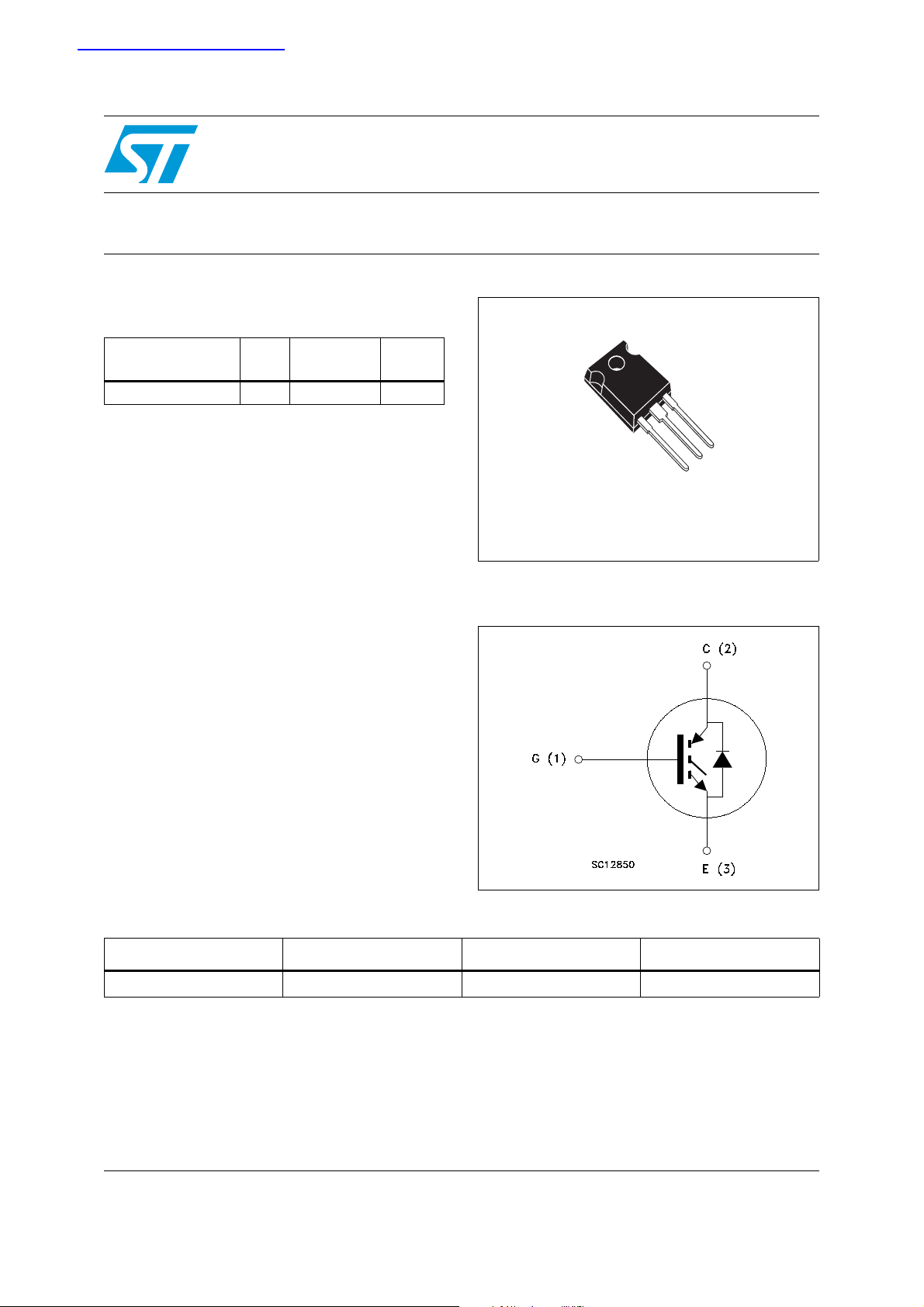
Figure 1. Internal schematic diagram
Application
■ Induction heating
Table 1. Device summary
Order code Marking Package Packaging
STGW30N90D GW30N90D TO-247 Tube
July 2007 Rev 1 1/10
This is preliminary information on a new product now in development or undergoing evaluation. Details are subject to
change without notice.
www.st.com
10

Contents STGW30N90D
Contents
1 Electrical ratings . . . . . . . . . . . . . . . . . . . . . . . . . . . . . . . . . . . . . . . . . . . . 3
2 Electrical characteristics . . . . . . . . . . . . . . . . . . . . . . . . . . . . . . . . . . . . . 4
3 Test circuit . . . . . . . . . . . . . . . . . . . . . . . . . . . . . . . . . . . . . . . . . . . . . . . . 6
4 Package mechanical data . . . . . . . . . . . . . . . . . . . . . . . . . . . . . . . . . . . . . 7
5 Revision history . . . . . . . . . . . . . . . . . . . . . . . . . . . . . . . . . . . . . . . . . . . . 9
2/10

STGW30N90D Electrical ratings
1 Electrical ratings
Table 2. Absolute maximum ratings
Symbol Parameter Value Unit
V
CES
I
C
I
C
I
CL
V
P
TOT
T
T
1. Calculated according to the iterative formula:
ICTC()
2. Vclamp=900V, Tj=125°C, RG=10Ω, VGE=15V
Collector-emitter voltage (VGS = 0)
(1)
Collector current (continuous) at 25°C 60 A
(1)
Collector current (continuous) at 100°C 30 A
(2)
Collector current (pulsed) 135 A
Gate-emitter voltage ±25 V
GE
Total dissipation at TC = 25°C
I
Diode RMS forward current at TC = 25°C
f
Operating junction temperature
j
Storage temperature
stg
T
–
---------------------------------- --------------------------------------------- -----------------------=
R
THJ C–VCESAT MAX()TCIC
JMAXTC
,()×
Table 3. Thermal resistance
900 V
220 W
30 A
–55 to 150 °C
Symbol Parameter Value Unit
Rthj-case Thermal resistance junction-case 0.57 °C/W
Rthj-amb Thermal resistance junction-ambient (diode) 1.6 °C/W
Rthj-amb Thermal resistance junction-ambient (IGBT) 50 °C/W
3/10
 Loading...