


1
2
3
查询STF724供应商
Features
■ SURFACE MOUNTING DEVICES IN MEDIUM
POWER SOT-223 AND SOT-89 PACKAGE
■ AVAILABLE IN TAPE & REEL PACKING
■ IN COMPLIANCE WITH THE 2002/93/EC
EUROPEAN DIRECTIVE
Applications
STF724
STN724
NPN MEDIUM POWER TRANSISTORS
2
■ VOLTAGE REGULATION
■ RELAY DRIVER
■ GENERIC SWITCH
Description
The STF724 and STN724 are PNP transistors
manufactured using planar Technology resulting
in rugged high performance devices.
Internal Schematic Diagram
SOT-223
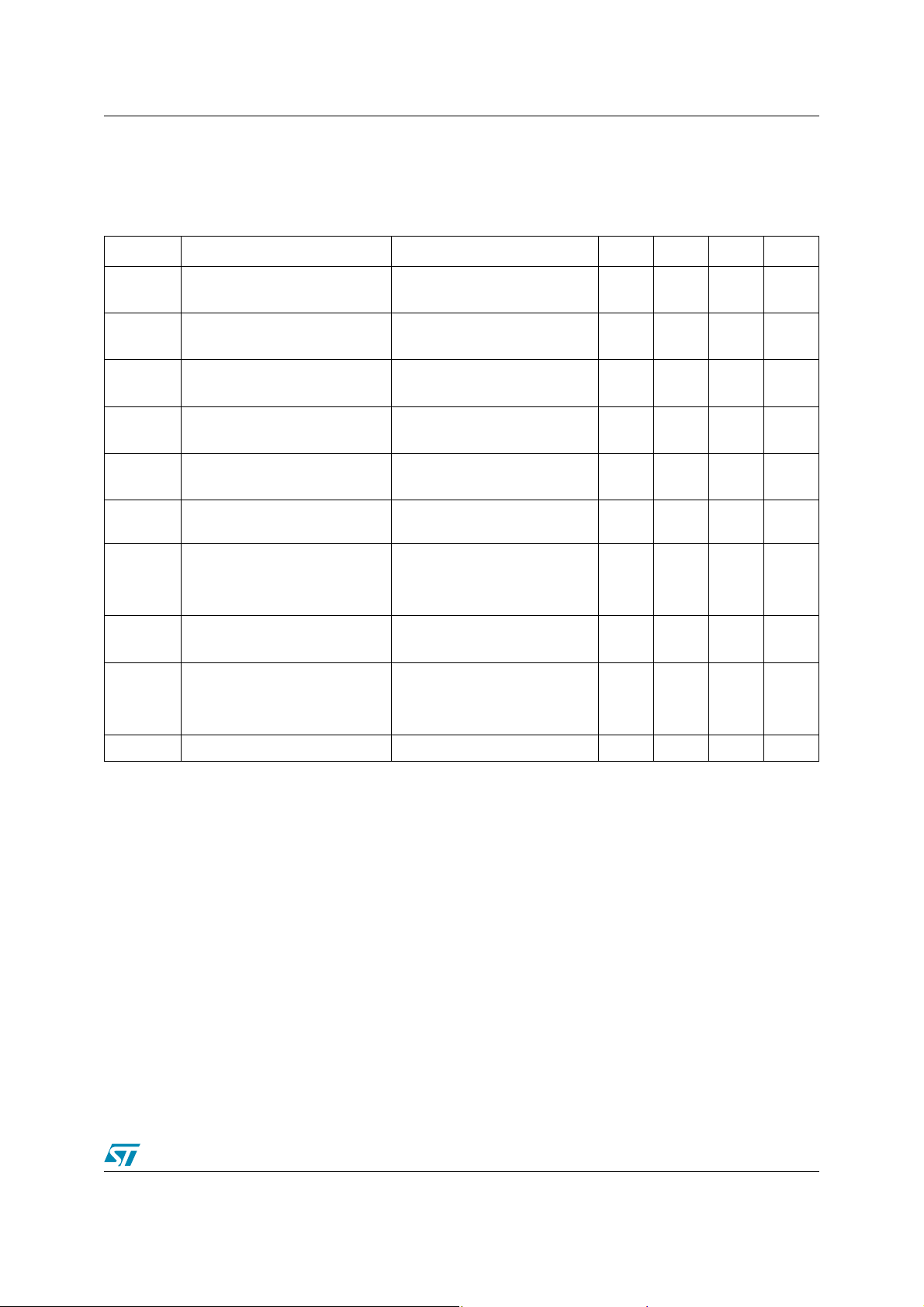
Order codes
Part Number Marking Package Packing
SOT-89
STF724 724 SOT-89 Tape & reel
STN724 N724 SOT-223 Tape & reel
Rev 1
October 2005 1/10
www.st.com
10

1 Absolute Maximum Ratings STF724 - STN724
1 Absolute Maximum Ratings
Table 1. Absolute Maximum Rating
Symbol Parameter Value Unit
STF724 STN724
V
V
V
P
T
CBO
CEO
EBO
I
I
CM
I
I
BM
TOT
STG
T
Collector-Base Voltage (IE = 0)
Collector-Emitter Voltage (IB = 0)
Collector-Base Voltage (IC = 0)
Collector Current 3 A
C
Collector Peak Current (tP < 5ms)
Base Current 1 A
B
Base Peak Current (tP < 5ms)
Total di ssipation at Tc = 25°C
60 V
30 V
5V
6A
2A
1.4 1.6 W
Storage Temperature -65 to 150
Max. Operating Junction Temperature 150
J
Table 2. Thermal Data
Symbol Parameter Value Unit
SOT-89 SOT-223
R
thj-amb
Note: 1
Note: 1 Device mounted on a PCB area of 1 cm
Thermal Resista nce Junction-Amb ____________________Max 89 78 °C/W
2
.
°C
2/10
STF724 - STN724 2 Electrical Char acteristics
2 Electrical Characteristics
Table 3. Electrical Characteristics (T
= 25°C; unless otherwise specified)
CASE
Symbol Parameter T est Conditions Min. T yp. Max. Unit
I
CES
I
CEO
I
EBO
V
(BR)CBO
V
(BR)CEO
Note 2
V
(BR)EBO
V
CE(sat)
Note 2
V
BE(sat)
Note 2
h
Collector Cut-off Current
= 0)
(V
BE
Collector Cut-off Current
= 0)
(I
B
Emitter Cut-off Current
= 0)
(I
C
Collector-Base
Breakdown Voltage (I
Collector-Emit ter Breakdown
Voltage (I
= 0)
B
Collector-Emit ter Breakdown
Voltage (I
= 0)
C
Collector-Emitter Saturation
Voltage
Base-Emitter Saturation Voltage
DC Current Gain
FE
f
Transistor Frequency
T
= 0)
E
= 60V
V
CE
= 30V
V
CE
= 5V
V
EB
= 100μA
I
C
= 10 mA
I
C
= 100 μA
I
E
I
= 1 A IB = 50 mA
C
I
= 2 A IB = 100 mA
C
I
= 3 A IB = 150 mA
C
= 2 A IB = 100 mA
I
C
I
= 100 mA V
C
I
= 1 A V
C
= 3 A V
I
C
V
= 10 V Ic= 0.1 A
CE
CE
CE
CE
= 2 V
= 2 V
= 2 V
10 μA
100 μA
10 μA
60 V
30 V
5V
0.4
0.7
1.1
1.2 V
100
80
300
30
100 MHz
2 Pulsed duration = 300 μs, duty cycle ≤1.5%.
V
V
V
3/10

2 Electrical Characteristics STF724 - STN724
2.1 Electrical characteristics (curve)
Figure 1. DC Current Gain Figur e 2. DC Current Gain
Figure 3. Collector-emitter saturation voltage Figure 4. Base-emitter satura tion voltage
Figure 5. Switching times on resistive load Figure 6. Switching times resistive on load
4/10

STF724 - STN724 2 Electrical Char acteristics
Figure 7. Reverse biased area
5/10

3 Package Mechani cal Data STF724 - STN724
3 Package M echanical Data
In order to meet environmental requirements, ST offers these devices in ECOPACK®
packages. These packages have a Lead-free second level interconnect . The category of
second level interconnect is marked on the package and on the inner box label, in compliance
with JEDEC Standard JESD97. The maximum ratings related to soldering conditions are also
marked on the inner box label. ECOP ACK is an ST trademark. ECOPACK specifications are
available at: www.st.com
6/10

STF724 - STN724 3 Package Mechan ical Data
P025H
SOT-89 MECHANICAL DATA
DIM.
MIN. TYP. MAX. MIN. TYP. MAX.
A 1.4 1.6 55.1 63.0
B 0.44 0.56 17.3 22.0
B1 0.36 0.48 14.2 18.9
C 0.35 0.44 13.8 17.3
C1 0.35 0.44 13.8 17.3
D 4.4 4.6 173.2 181.1
D1 1.62 1.83 63.8 72.0
E 2.29 2.6 90.2 102.4
e 1.42 1.57 55.9 61.8
e1 2.92 3.07 115.0 120.9
H 3.94 4.25 155.1 167.3
L 0.89 1.2 35.0 47.2
mm mils
7/10

3 Package Mechani cal Data STF724 - STN724
SOT-223 MECHANICAL DATA
DIM.
MIN. TYP. MAX. MIN. TYP. MAX.
A 1.80 0.071
B 0.60 0.70 0.80 0.024 0.027 0.031
B1 2.90 3.00 3.10 0.114 0.118 0.122
c 0.24 0.26 0.32 0.009 0.010 0.013
D 6.30 6.50 6.70 0.248 0.256 0.264
e 2.30 0.090
e1 4.60 0.181
E 3.30 3.50 3.70 0.130 0.138 0.146
H 6.70 7.00 7.30 0.264 0.276 0.287
V10
A1 0.02
mm inch
o
o
10
8/10
P008B

STF724 - STN724 4 Revision History
4 Revision History
Date Revision Changes
12-Oct-2005 1 Initial release.
9/10

4 Revision Hist ory S TF724 - STN724
I
s
o
d
b
ct
t
ot
a
nformation furnished is believed to be accurate and reliable. However, STMicroelectronics assumes no responsibility for the consequence
f use of such information nor for any infringement of patents or other rights of third parties which may result from its use. No license is grante
y implic ation or oth erwise unde r any patent or patent rights of ST M i croelectronics. Specification s mentioned in this pub l ic at i on are sub je
o change without notice. This publication supersedes and replaces all information previously supplied. STMicroelectronics products are n
uthoriz ed for use as crit ical component s i n l ife support devices or system s without expr ess written approval of STMicroelectronics.
The ST logo is a registered trademark of STM i croelectroni cs.
All other nam es are the property of their respective ow ners
© 2005 STMi croelectro ni cs - All rights reserved
Austra l i a - Be l gi um - Brazil - C anada - China - Czech Republic - Finland - France - Germany - Hong Kong - Indi a - Israel - Ital y - Japan -
Malaysi a - M al ta - Morocco - Singapore - Sp ai n - S weden - Swit zerland - United Kingdom - Uni ted States of Am erica
STMicroelectronics group of companies
www.st.com
10/10
 Loading...