

Page 1

TN1239
Technical note
How to change DCF STCU configuration
Introduction
The SPC58 family integrates a dedicated safety module to configure, control and execute
self-test operations. This module is called Self-Test Control Unit (STCU2).
The user can configure the STCU2 in two ways. The first way uses the standard register
access from user application. The second way exploits the Device Configuration Format
(DCF) records.
This document explains the correct procedure to update a STCU configuration which has
been already set by the specific DCF records in UTest memory. It focuses only on the
second way to configure the STCU.
As a prerequisite the reader should be familiar with the functionality of STCU2, DCF, SSCM
and UTest flash. For any details on these topics, refer to the reference manual.
September 2016 DocID029694 Rev 1 1/11
www.st.com
11
Page 2

Contents TN1239
Contents
1 Programming of STCU2 . . . . . . . . . . . . . . . . . . . . . . . . . . . . . . . . . . . . . . 3
2 How STCU2 configuration can be updated . . . . . . . . . . . . . . . . . . . . . . . 4
3 Limitation and prerequisites . . . . . . . . . . . . . . . . . . . . . . . . . . . . . . . . . . 6
4 Conclusion . . . . . . . . . . . . . . . . . . . . . . . . . . . . . . . . . . . . . . . . . . . . . . . . . 7
5 Reference documents . . . . . . . . . . . . . . . . . . . . . . . . . . . . . . . . . . . . . . . . 8
6 Acronyms . . . . . . . . . . . . . . . . . . . . . . . . . . . . . . . . . . . . . . . . . . . . . . . . . . 9
7 Revision history . . . . . . . . . . . . . . . . . . . . . . . . . . . . . . . . . . . . . . . . . . . 10
2/11 DocID029694 Rev 1
Page 3
TN1239 Programming of STCU2
1 Programming of STCU2
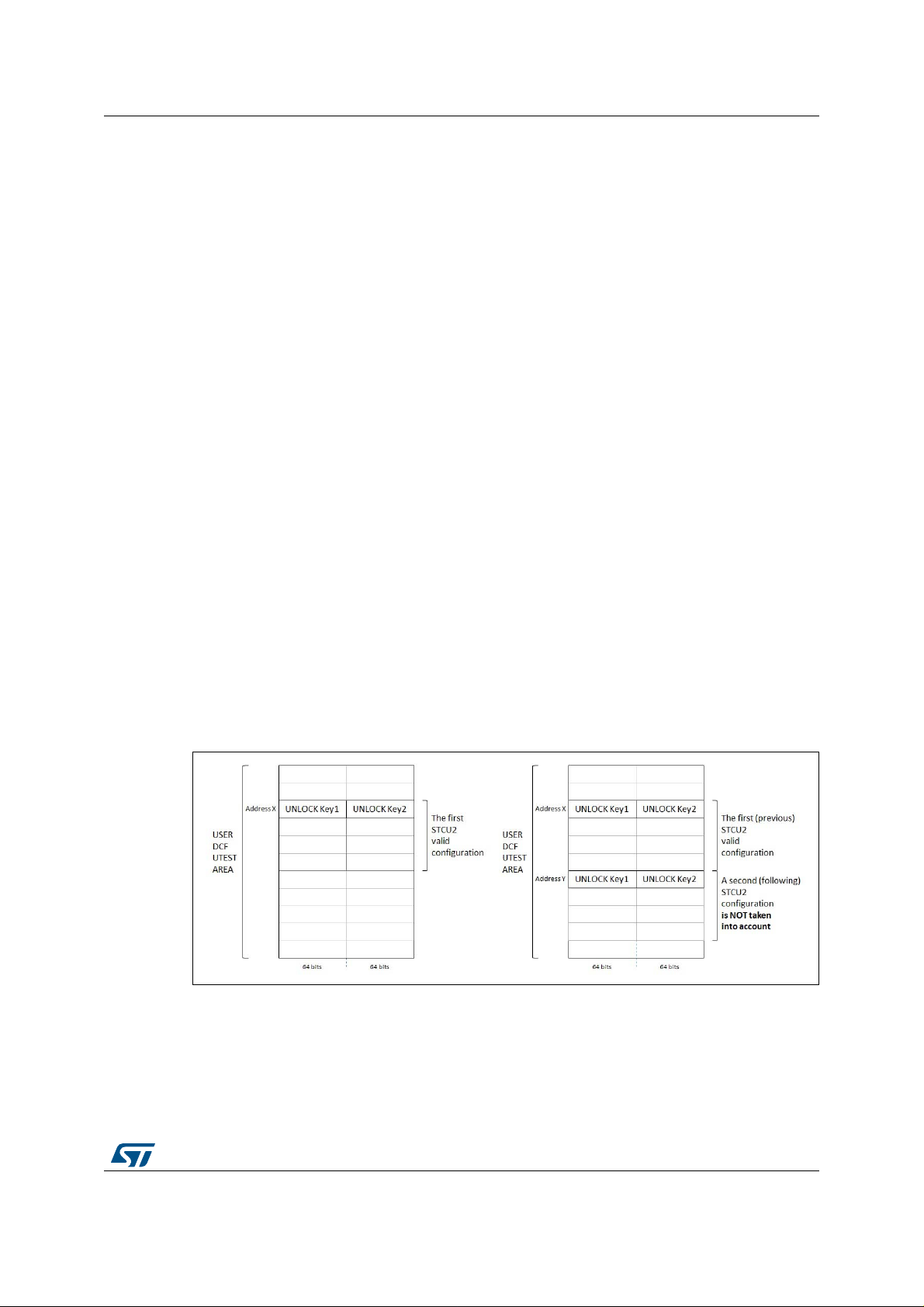
The normal flow to program STCU2 starts by providing the unlock keys and afterwards the
rest of the configuration (left side of Figure 1).
Unlock keys are static keys. The user can find their values in the STCU chapter of the
reference manual.
The STCU loads the configuration only if the user provides the correct unlock keys. If the
unlock keys are not correct, the STCU ignores the following configuration.
The user passes these values to the STCU by writing them into the UTest sector of the
Flash as DCF records as shown on the left side of Figure 1.
A problem occurs in case the user needs to change the STCU configuration. It means that
the user has programmed at least a pair of unlock keys into UTest.
Given that the STCU2 considers only the first valid unlock keys and the following
configuration, after the first acceptance of a configuration, STCU2 does not accept any other
settings even if the provided unlock keys are correct. The SSCM reads the DCF
incrementally from lower to higher addresses.
The right side of Figure 1 shows two different configurations of the STCU. Both
configurations start with the correct unlock keys:
1. First configuration starts at address X
2. Second configuration starts at address Y
Even if the second configuration starts with th e correct unlo ck keys, the STCU ignores it. As
a result, the STCU runs the L/MBIST accordingly with the configuration that starts at
address X.
Next section explains how to instruct the STCU to load the second configuration and discard
the first one.
Figure 1. STCU unlock keys organization
DocID029694 Rev 1 3/11
11
Page 4
How STCU2 configuration can be updated TN1239
2 How STCU2 configuration can be updated
As explained in the previous chapter, simply writing a second STCU configuration at
different location does not cause an y change in the configura tion that the STCU loads, such
as the first one.
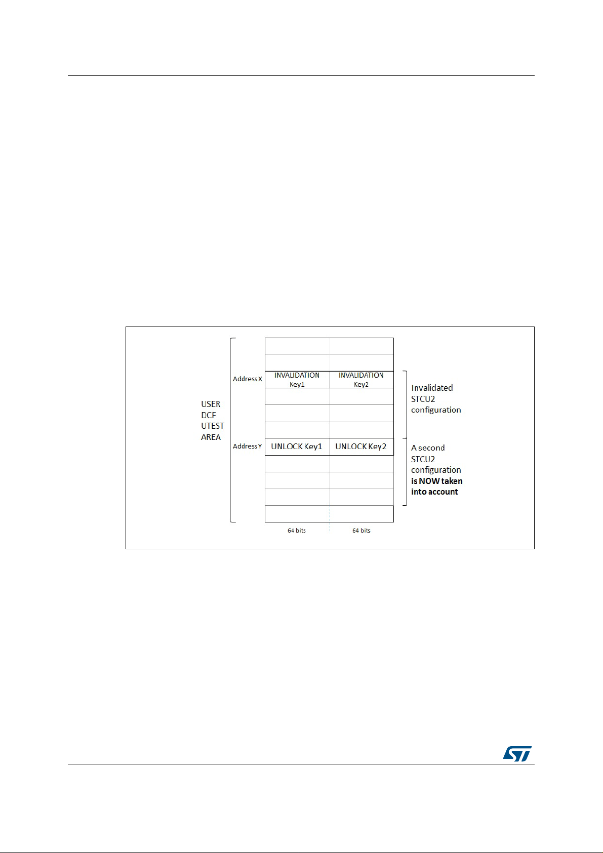
Since the UTest sector is not erasable, if the user wants to change the STCU con figuration
he must invalidate the first configuration. It means invalidating the first instance of the unlock
keys.
As a consequence, STCU2 reads unlock keys that are not correct and ignores the following
configuration.
With reference to Figure 2, if the user invalidates the unlock keys at address X the STCU
ignores the first configuration and loads the second one.
If needed, the user can repeat the process by adding a third configuration and invalidating
the unlock keys at address Y and so forth.
Figure 2. Make STCU unlock key invalid
Invalidating means overwriting the unlock keys with incorrect keys. The user, however , does
this operation carefully due to the ECC/EDC.
The ECC/EDC protects the UTest content. It means that the UTest contains not only the
data, but also some redundant bits. The hardwar e can correct or detect some errors by
comparing the data and the redundan t bits. This process is transparent from the standpoint
of the user who cannot access the redundant bits.
For this reason, if the user overwrites the unlock keys with random data, there is a risk that
the ECC/EDC logic detects one or more not correctable errors. In case of this event the
sample does not start.
Under those circumstances, the user must adopt specific values that do not cause the
ECC/EDC errors. These values are visible in Table 1.
4/11 DocID029694 Rev 1
Page 5

TN1239 How STCU2 configuration can be updated
Table 1. Physical values of unlock and invalidation keys
Key 1 Key 2 Complete DCF key 1 Complete DCF key 2
Unlock 0xD3FEA98B 0x2C015674 0xD3FEA98B00080008 0x2C01567400080008
Invalidation 0xD3BCA98B 0x28011674 0xD3BCA98B00080008 0x2801167400080008
DocID029694 Rev 1 5/11
11
Page 6

Limitation and prerequisites TN1239
3 Limitation and prerequisites
These invalidation keys are effective only if unlock keys are aligned at 128 bits, otherwise
the ECC must be computed explicitly for given data.
The user adopts the invalidation keys only in case val id unl oc k ke ys a re sa ved i n UTest and
a new configuration is applied.
Invalidation keys must be written at exact positions of unlock keys which means overwrite
the unlock keys.
6/11 DocID029694 Rev 1
Page 7

TN1239 Conclusion
4 Conclusion
The update of STCU2 configuration is possible even if there are strict rules which the user
must consider.
If the user follows these rules this is no a risky operation. In addition, change of STCU2
configuration is an exceptional state which occurs mainly during developing phase and not
in final application.
DocID029694 Rev 1 7/11
11
Page 8

Reference documents TN1239
5 Reference documents
SPC58NE84C3, SPC58NE84E7, SPC58EG84C3 reference manuals, Rev2, Feb 2016
8/11 DocID029694 Rev 1
Page 9

TN1239 Acronyms
6 Acronyms
Ta bl e 2. Acronyms
Acronym Name
STCU2 Self-test control unit
DCF Device configuration format
SSCM System status and configuration module
DocID029694 Rev 1 9/11
11
Page 10

Revision history TN1239
7 Revision history
Date Revision Changes
26-Sept-2016 1 Initial release
Table 3. Document revision history
10/11 DocID029694 Rev 1
Page 11

TN1239
IMPORTANT NOTICE – PLEASE READ CAREFULLY
STMicroelectronics NV and its subsidiaries (“ST”) reserve the right to make changes, corrections, enhancements, modifications, and
improvements to ST products and/or to this document at any time without notice. Purchasers should obtain the latest relevant information on
ST products before placing orders. ST products are sold pursuant to ST’s terms an d conditions of sale in place at the time of order
acknowledgement.
Purchasers are solely responsible for the choice, selection, and use of ST products and ST assumes no liability for application assistance or
the design of Purchasers’ products.
No license, express or implied, to any intellectual property right is granted by ST herein.
Resale of ST products with provisions different from the information set forth herein shall void any warranty granted by ST for such product.
ST and the ST logo are trademarks of ST. All other product or service names are the property of their respective owners.
Information in this document supersedes and replaces information previously supplied in any prior versions of this document.
© 2016 STMicroelectronics – All rights reserved
DocID029694 Rev 1 11/11
11
 Loading...