

ST STA2064 User Manual

infotainment application processor with embedded GPS
Features
■
ARM1176 533 MHz host processor
– Cache: 32 KB instruction, 32 KB data
– Vector floating point unit
■ High performance embedded GPS subsystem
– Parallel acquisition engines for 8 GPS
satellites or 4 Galileo satellites
– 32 tracking channels for all satellites in view
– 5 correlators per channel for urban canyon
robustness
– Multibit signal processing hardware
■ Advanced power management
– Separated power islands for ultra low
power mode
– Dynamic core frequency scaling
– 512-Byte embedded SRAM for back-up
■ System infrastructure
– LP DDR/DDR2 controller: 16 bit data
256 MB addressable (333 MHz DDR2,
200 MHz LPDDR)
– One bank of 32 KB embedded SRAM
– 64-channel vector interrupt controller (VIC)
– 2 DMA controllers, 16 physical channels
– 32 DMA request for each controller
– Two external DMA requests are supported
■ Display and graphics
– Color LCD controller for STN,TFT or HR-
TFT panels with 18-bit parallel RGB
interface
– Integrated touch screen controller and ADC
– 3D advanced graphics acceleration
– JPEG baseline profile decoder
■ High throughput interfaces
– 1 ports USB 2.0 OTG with integrated
physical layer
– 2 SD/MMC up to 8 bit data, all bootable
STA2064
Cartesio™ family
Data brief
TFBGA289 (15x15x1.2mm)
■ Audio interfaces and features
– Three multichannel serial ports (I2S/TDM)
– SPDIF input interface
– C3 hardware reed-solomon decoder
– Sample rate converter
■ Standard interfaces
– Four 16-bit input capture/output compare
– Pulse width light modulator (PWL)
– Four autobaud UART
– Three I
– Two synchronous serial port (SSP, SPI)
– 65 GPIO over 5 ports
■ One controller area network (CAN) in
automotive version
■ Programmable voltage IOs: 1.8 V, 2.5 V, 3.3 V
■ V
DDIO_ON
1.25 ±3%V
■ TFBGA 289, 0.8 mm pitch package, packing in
tray
■ Ambient temperature range: -40 / +85 °C
Table 1. Device summary
Order code
STA2064N Consumer 533 MHz No
STA2064A Automotive 533 MHz 1x
2
C multimaster/slave interfaces
: 1.8 ±10%V, V
Qualification
grade
: VDD,
DD_ON
CPU freq. CAN
October 2009 Doc ID 16057 Rev 3 1/19
For further information contact your local STMicroelectronics sales office.
www.st.com
19

Contents STA2064
Contents
1 Description . . . . . . . . . . . . . . . . . . . . . . . . . . . . . . . . . . . . . . . . . . . . . . . . . 4
2 System description . . . . . . . . . . . . . . . . . . . . . . . . . . . . . . . . . . . . . . . . . . 5
2.1 MCU . . . . . . . . . . . . . . . . . . . . . . . . . . . . . . . . . . . . . . . . . . . . . . . . . . . . . . 5
2.2 Embedded memories . . . . . . . . . . . . . . . . . . . . . . . . . . . . . . . . . . . . . . . . . 5
2.2.1 Embedded SRAM (eSRAM) . . . . . . . . . . . . . . . . . . . . . . . . . . . . . . . . . . 5
2.3 System functions . . . . . . . . . . . . . . . . . . . . . . . . . . . . . . . . . . . . . . . . . . . . 5
2.3.1 System and reset controller (SRC) . . . . . . . . . . . . . . . . . . . . . . . . . . . . . 5
2.3.2 PMU . . . . . . . . . . . . . . . . . . . . . . . . . . . . . . . . . . . . . . . . . . . . . . . . . . . . . 5
2.3.3 DMA . . . . . . . . . . . . . . . . . . . . . . . . . . . . . . . . . . . . . . . . . . . . . . . . . . . . . 5
2.3.4 Vectored interrupt controller (VIC) . . . . . . . . . . . . . . . . . . . . . . . . . . . . . . 5
2.3.5 GPIOs . . . . . . . . . . . . . . . . . . . . . . . . . . . . . . . . . . . . . . . . . . . . . . . . . . . 5
2.3.6 Real-time clock (RTC) . . . . . . . . . . . . . . . . . . . . . . . . . . . . . . . . . . . . . . . 6
2.3.7 Real-time timer (RTT) . . . . . . . . . . . . . . . . . . . . . . . . . . . . . . . . . . . . . . . 6
2.3.8 Always_ON supply . . . . . . . . . . . . . . . . . . . . . . . . . . . . . . . . . . . . . . . . . . 6
2.3.9 Enhanced function timer (EFT) . . . . . . . . . . . . . . . . . . . . . . . . . . . . . . . . 6
2.3.10 Watchdog timer (WDT) . . . . . . . . . . . . . . . . . . . . . . . . . . . . . . . . . . . . . . 6
2.4 Memory interfaces . . . . . . . . . . . . . . . . . . . . . . . . . . . . . . . . . . . . . . . . . . . 6
2.4.1 SD/MMC . . . . . . . . . . . . . . . . . . . . . . . . . . . . . . . . . . . . . . . . . . . . . . . . . 6
2.4.2 DDR-SDRAM controller . . . . . . . . . . . . . . . . . . . . . . . . . . . . . . . . . . . . . . 7
2.5 Audio/video functions . . . . . . . . . . . . . . . . . . . . . . . . . . . . . . . . . . . . . . . . . 7
2.5.1 C3 . . . . . . . . . . . . . . . . . . . . . . . . . . . . . . . . . . . . . . . . . . . . . . . . . . . . . . 7
2.5.2 Sample rate converter (SaRaC) . . . . . . . . . . . . . . . . . . . . . . . . . . . . . . . 7
2.5.3 JPEG decoder . . . . . . . . . . . . . . . . . . . . . . . . . . . . . . . . . . . . . . . . . . . . . 7
2.5.4 Smart graphic accelerator (SGA) . . . . . . . . . . . . . . . . . . . . . . . . . . . . . . . 7
2.5.5 Color LCD controller (CLCD) . . . . . . . . . . . . . . . . . . . . . . . . . . . . . . . . . . 7
2.6 Communication interfaces . . . . . . . . . . . . . . . . . . . . . . . . . . . . . . . . . . . . . 8
2.6.1 USB . . . . . . . . . . . . . . . . . . . . . . . . . . . . . . . . . . . . . . . . . . . . . . . . . . . . . 8
2.6.2 UART . . . . . . . . . . . . . . . . . . . . . . . . . . . . . . . . . . . . . . . . . . . . . . . . . . . . 8
2.6.3 I2C . . . . . . . . . . . . . . . . . . . . . . . . . . . . . . . . . . . . . . . . . . . . . . . . . . . . . . 8
2.6.4 MSP . . . . . . . . . . . . . . . . . . . . . . . . . . . . . . . . . . . . . . . . . . . . . . . . . . . . . 8
2.6.5 SSP . . . . . . . . . . . . . . . . . . . . . . . . . . . . . . . . . . . . . . . . . . . . . . . . . . . . . 8
2.6.6 SPDIF . . . . . . . . . . . . . . . . . . . . . . . . . . . . . . . . . . . . . . . . . . . . . . . . . . . 8
2.6.7 AC97 controller . . . . . . . . . . . . . . . . . . . . . . . . . . . . . . . . . . . . . . . . . . . . 9
2/19 Doc ID 16057 Rev 3

STA2064 Contents
2.6.8 CAN . . . . . . . . . . . . . . . . . . . . . . . . . . . . . . . . . . . . . . . . . . . . . . . . . . . . . 9
2.7 Specific functions . . . . . . . . . . . . . . . . . . . . . . . . . . . . . . . . . . . . . . . . . . . . 9
2.7.1 GPS . . . . . . . . . . . . . . . . . . . . . . . . . . . . . . . . . . . . . . . . . . . . . . . . . . . . . 9
2.7.2 Touchscreen controller/ADC . . . . . . . . . . . . . . . . . . . . . . . . . . . . . . . . . 10
2.7.3 Multisupply IO ring . . . . . . . . . . . . . . . . . . . . . . . . . . . . . . . . . . . . . . . . . 10
2.7.4 Driving strength and slew rate programmability . . . . . . . . . . . . . . . . . . . 11
3 System features introduction . . . . . . . . . . . . . . . . . . . . . . . . . . . . . . . . . 12
3.1 Power region partition . . . . . . . . . . . . . . . . . . . . . . . . . . . . . . . . . . . . . . . 12
3.2 Frequency region partition . . . . . . . . . . . . . . . . . . . . . . . . . . . . . . . . . . . . 12
3.3 Frequency and power range . . . . . . . . . . . . . . . . . . . . . . . . . . . . . . . . . . . 13
3.4 Power states . . . . . . . . . . . . . . . . . . . . . . . . . . . . . . . . . . . . . . . . . . . . . . . 14
3.5 System wakeup and power down . . . . . . . . . . . . . . . . . . . . . . . . . . . . . . . 15
3.6 IO groups . . . . . . . . . . . . . . . . . . . . . . . . . . . . . . . . . . . . . . . . . . . . . . . . . 16
4 Package information . . . . . . . . . . . . . . . . . . . . . . . . . . . . . . . . . . . . . . . . 17
5 Revision history . . . . . . . . . . . . . . . . . . . . . . . . . . . . . . . . . . . . . . . . . . . 18
Doc ID 16057 Rev 3 3/19
Description STA2064
1 Description
STA2064 is a highly integrated SOC application processor combining host capability with
high performance embedded GPS.
STA2064 targets vehicle head units and mobile navigation (PND), telematics, infotainment,
advanced audio and connectivity systems. The STA2064 provides all the elements that are
essential to build a cost effective solution.
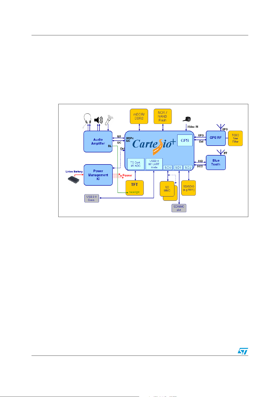
Figure 1. Application implementation example
4/19 Doc ID 16057 Rev 3

STA2064 System description
2 System description
2.1 MCU
ARM1176-JZF advanced risc machine CPU up to 533 MHz (with Vdd greater or equal to
1.20 V and under process and temperature worst case conditions).
2.2 Embedded memories
2.2.1 Embedded SRAM (eSRAM)
The embedded SRAM is 8K x 32 (32 KB).
2.3 System functions
2.3.1 System and reset controller (SRC)
This provides a control interface for clock generation components external to the subsystem.
It also controls system-wide and peripherals-specific energy management features.
2.3.2 PMU
The power manager module controls the SLEEP to DEEP-SLEEP modes transition,
controls the external voltage switches on the Vdd and Vddio, monitors the external power
supply (via two signals, Vddok and BATOK), can force the emergency entry of the SDRAM
in self-refresh, and controls the wake-up from DEEP-SLEEP mode.
2.3.3 DMA
Direct memory access can be used with DMA peripherals. FIFO fill/empty requests from
these peripherals can be serviced immediately by the DMA Controller without CPU
interaction. Peripheral-to-peripheral and memory-to-memory DMA are also supported.
STA2064 features two DMA engines. Each DMA supports up to 8-channels and up to 32
requests.
2.3.4 Vectored interrupt controller (VIC)
The VIC allows the OS interrupt handler to quickly dispatch interrupt service routines in
response to peripheral interrupts.
2.3.5 GPIOs
Four GPIO ports provide 65 programmable inputs or outputs that can be controlled in two
modes:
● software mode through an APB bus interface
● hardware mode through a hardware control interface
Doc ID 16057 Rev 3 5/19

System description STA2064
2.3.6 Real-time clock (RTC)
The RTC provides a one second resolution clock. This keeps time when the system is
inactive and can be used to wake the system up when a programmed ‘alarm’ time is
reached. It has a clock trimming feature to compensate the drift of the 32.768 kHz crystal.
2.3.7 Real-time timer (RTT)
The RTT has the possibility of being clocked off. This reduces the always_on domain
consumption during Deep Sleep. By default the RTT has its clock enabled.
2.3.8 Always_ON supply
The “Always_ON” domain retains its two separate supplies, one for the core logic (V
and one for the IOs (V
The V
supply is equal to VDD during normal operation but, with the goal of reaching the
DDON
IOON
).
lowest consumption possible, can also be configured as low as 1.0 ±10%V when the device
is in deep-sleep.
2.3.9 Enhanced function timer (EFT)
STA2064 features 4 16-bit EFTs. Each of the four EFT timers has a 16-bit free-running
counter with 7-bit prescaler, up to two input capture/output compare functions, a pulse
counter function, and a PWM channel with selectable frequency.
2.3.10 Watchdog timer (WDT)
This OS resource is used to trigger a system reset in the event of software failure.
2.4 Memory interfaces
2.4.1 SD/MMC
STA2064 features two SD/SDIO/MMC interfaces up to 52 MHz / one up to 8-bit data, the
other up to 4-bit data. The main clock available to the peripherals is:
● PLL2CLK/13 (when PLL2CLK is 624 MHz and SRC_MMC52 = 0, 48 MHz will be
generated)
● PLL2CLK/12 (when PLL2CLK is 624 MHz and SRC_MMC = 1, 52 MHz will be
generated)
● PLL2CLK/9 (when PLL2CLK is 432 MHz, 48 MHz will be generated)
DDON
)
The peripheral is compliant to the following standards:
● MMC 4.4
● SD 2.0/Part 1 - Physical Layer
● SD 2.0/Part E1 - SDIO Specification
6/19 Doc ID 16057 Rev 3
 Loading...