

ST7MDT10-20/DVP
DIP20/SO20 Connection Kit for ST7MDT10-DVP3
DATA BRIEF
The DIP20/SO20 Connection Kit (ST7 MDT10-
20/DVP) provides the hardware you need to
connect your ST7MDT10-DVP3 emulator to your
application when debugging applications for ST7
microcontrollers in DIP20 and SO20 packages.
Connection Kit Contents
■ DIP20 adapter (DB586) – Allows the
connection of your ST7MDT10-DVP3 emulator
to your application board in place of your ST7.
■ DIP20-DIP20 device adapter (DB535) –
Adapts the pin out of the DIP20 adapter to the
DIP20 footprint of the ST7 on your application
board.
■ DIP20-SO20 device adapter (DB093) –
Adapts the DIP20 adapter to SO20 footprint of
the ST7 on your application board.
The
34-pin flat cable
for connection between the
emulator and adapter is provided with your
ST7MDT10-DVP3 emulator.
For more information...
■ ST7-DVP3 User Manual – Information
common to all DVP3 series emulators
■ ST7MDT10-DVP3 Probe User Guide –
Information specific to ST7MDT10-DVP3
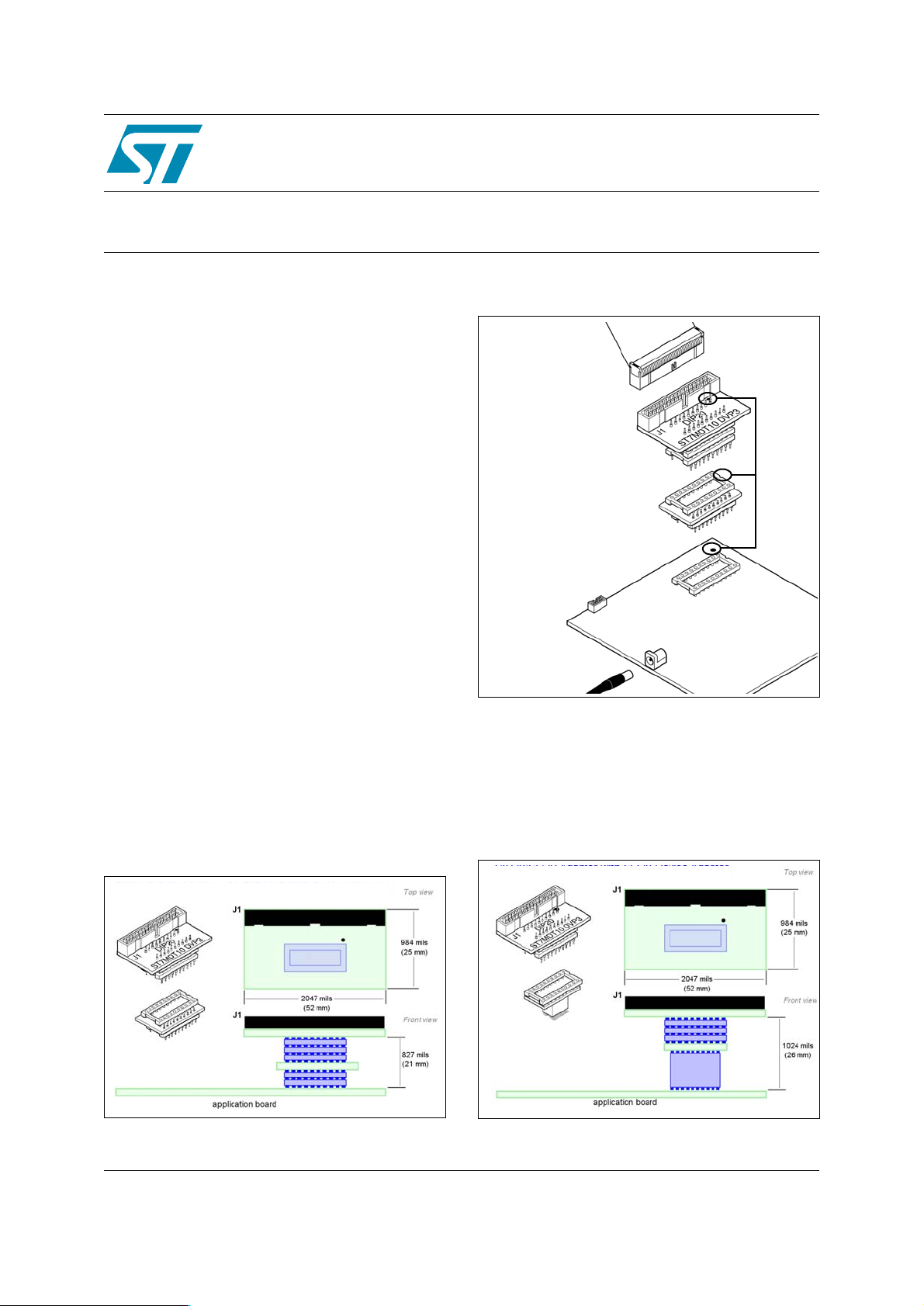
Figure 1. DIP20 adapter, DIP20 device adapter
DIP20 adapter (DB586)
Figure 2. DIP20 application board connection
2. Plug flat cable into the
J1 connector on the
adapter
3. Align pin 1 indicators, then
insert the pins of the DIP20
adapter into the DIP20-DIP20
device adapter.
4. Align pin 1 indicators, then
insert the pins of the DIP20DIP20 device adapter into the
socket on the application
board.
1. Solder socket to
application board.
Pin 1
Indicators
The pinouts of certain microcontrollers are askew
by 90° from the pinout of the DIP20 adapter. The
connection to an application requires the use of
the DIP20-DIP20 for the following supported
devices:
Figure 3. DIP20 adapter, SO20 device adapter
DIP20 adapter (DB586)
DIP20-SO20 device
DIP20-DIP20 device
adapter (DB535)
October 2005 1/3
adapter (DB093)
Rev 1
www.st.com
3
ST7MDT10-20/DVP
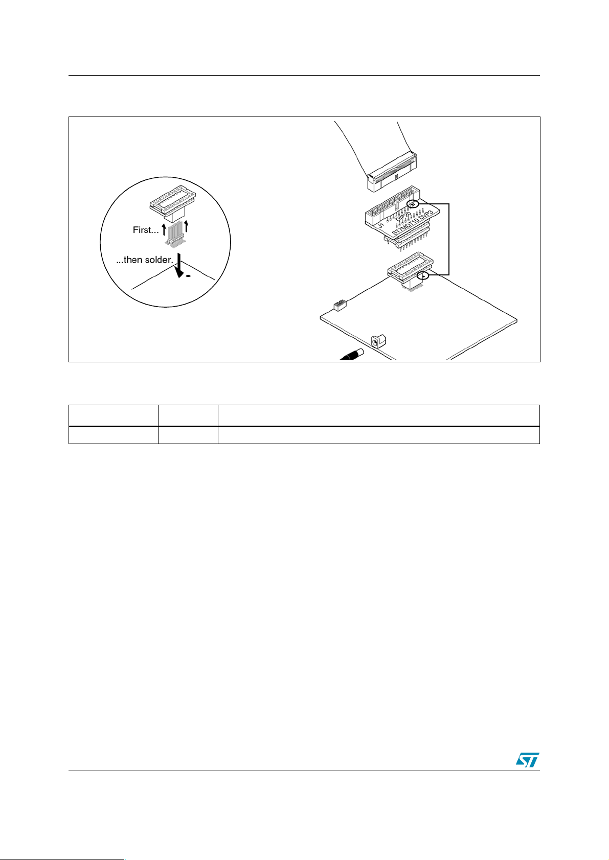
Figure 4. SO20 application board connection
1. Solder the connection pins to your
application board. When soldering, insert the
connection pins into the device adapter, which
serves as a support to ensure correct
alignment.
2. Plug flat cable into the
J1 connector on the
adapter
3. Align pin 1 indicators, then
insert the pins of the DIP20
adapter into the DIP20-SO20
device adapter.
Pin 1
Indicators
Revision history
Date Revision Changes
12-October-2005 1 Initial release.
2/3

ST7MDT10-20/DVP
Information furnished is believed to be accurate and reliable. However, STMicroelectronics assumes no responsibility for the consequences
of use of such information nor for any infringement of patents or other rights of third parties which may result from its use. No license is granted
by implication or otherwise under any patent or patent rights of STMicroelectronics. Specifications mentioned in this publication are subject
to change without notice. This publication supersedes and replaces all information previously supplied. STMicroelectronics products are not
authorized for use as critical components in life support devices or systems without express written approval of STMicroelectronics.
The ST logo is a registered trademark of STMicroelectronics.
All other names are the property of their respective owners
© 2005 STMicroelectronics - All rights reserved
STMicroelectronics group of companies
Australia - Belgium - Brazil - Canada - China - Czech Republic - Finland - France - Germany - Hong Kong - India - Israel - Italy - Japan -
Malaysia - Malta - Morocco - Singapore - Spain - Sweden - Switzerland - United Kingdom - United States of America
www.st.com
3/3
 Loading...