How it Works
Log In / Sign Up
Buy Points
How it Works
FAQ
Contact Us
Questions and Suggestions
Users
ST
Loading...
S
ST72E311
ST72E331
ST72F521
ST72F61
ST72F62
ST72F63B
ST72T121
ST72T311
ST72T331
ST75185C
ST7538Q
ST7540
2
ST7570
2
ST7580
2
ST7590
2
ST75 Series
ST763A
ST7920
ST7DALI
ST7DALIF2
ST7FLI49
ST7FLI49M
ST7FLIT1B
ST7FLITU0
ST7FLITUS
ST7FOXA0
ST7FOXF1
ST7FOXK1
ST7FOXK2
2
ST7GEME4
ST7LCRDIE6
ST7LCRE4U1
ST7LIT15BY0
ST7LITE02Y0
ST7LITE05Y0
ST7LITE09Y0
ST7LITE1
ST7LITE10B
ST7LITE15B
ST7LITE19B
ST7LITE2
ST7LITE30F2
ST7LITE35F2
ST7LITE39F2
ST7LITE49K2
ST7LITE49M
ST7LITES2Y0
ST7LITES5Y0
ST7LITEU05
ST7LITEU09
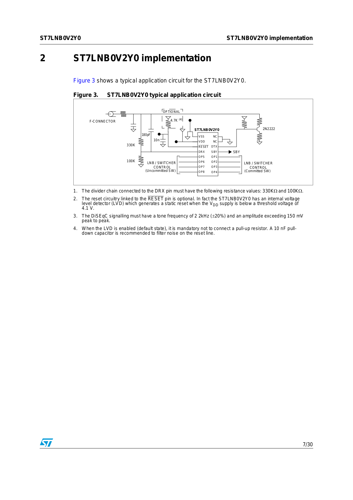
ST7LNB0V2Y0
ST7LNB1Y0
ST7MC1
3
ST7MC2
3
ST7MDT1
ST7MDT10-16
ST7MDT10-20
ST7MDT10-32
ST7MDT20-T32
ST7MDT20-T44
ST7MDT20-T64
ST7MDT20-T6A
ST7MDT20-T80
ST7MDTU3-EMU2B
ST7SCR1E4
ST7SCR1R4
ST8004
ST8024
ST8024L
ST802RT1A
ST802RT1B
2
ST890
ST8R00
ST90E30
ST90E31
ST90T30
ST90T31
ST92124R9T
ST92124V1Q
ST92124V1T
ST92150CR9T
ST92150CV1Q
ST92150CV1T
ST92150CV9T
ST92150JDV1Q
ST92150JDV1T
ST92163
ST92195C
ST92195D
ST92250CV2Q
ST92250CV2T
ST92F124R1
ST92F124R9
ST92F124V1
ST92F150CR1
ST92F150CR9
ST92F150CV1
ST92F150CV9
ST92F150JDV1
ST92F250CV2
Loading...
Loading...
Nothing found
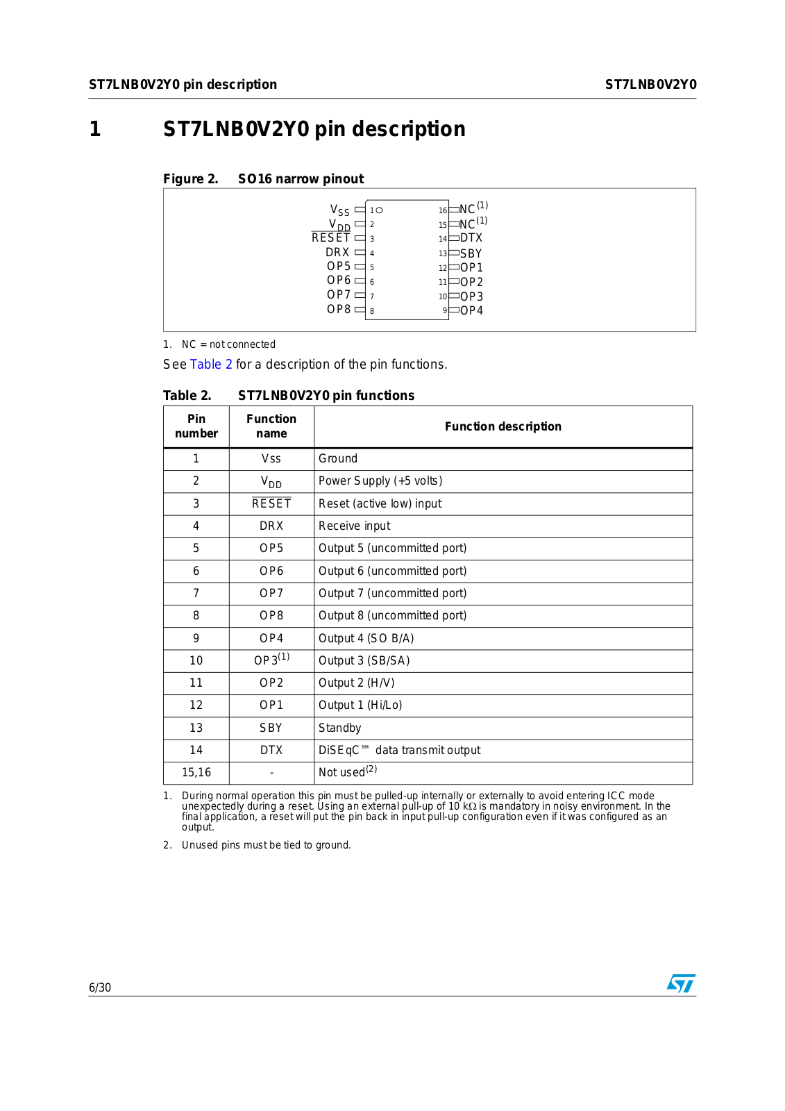
ST7LNB0V2Y0
User Manual
30 pgs
447.01 Kb
0
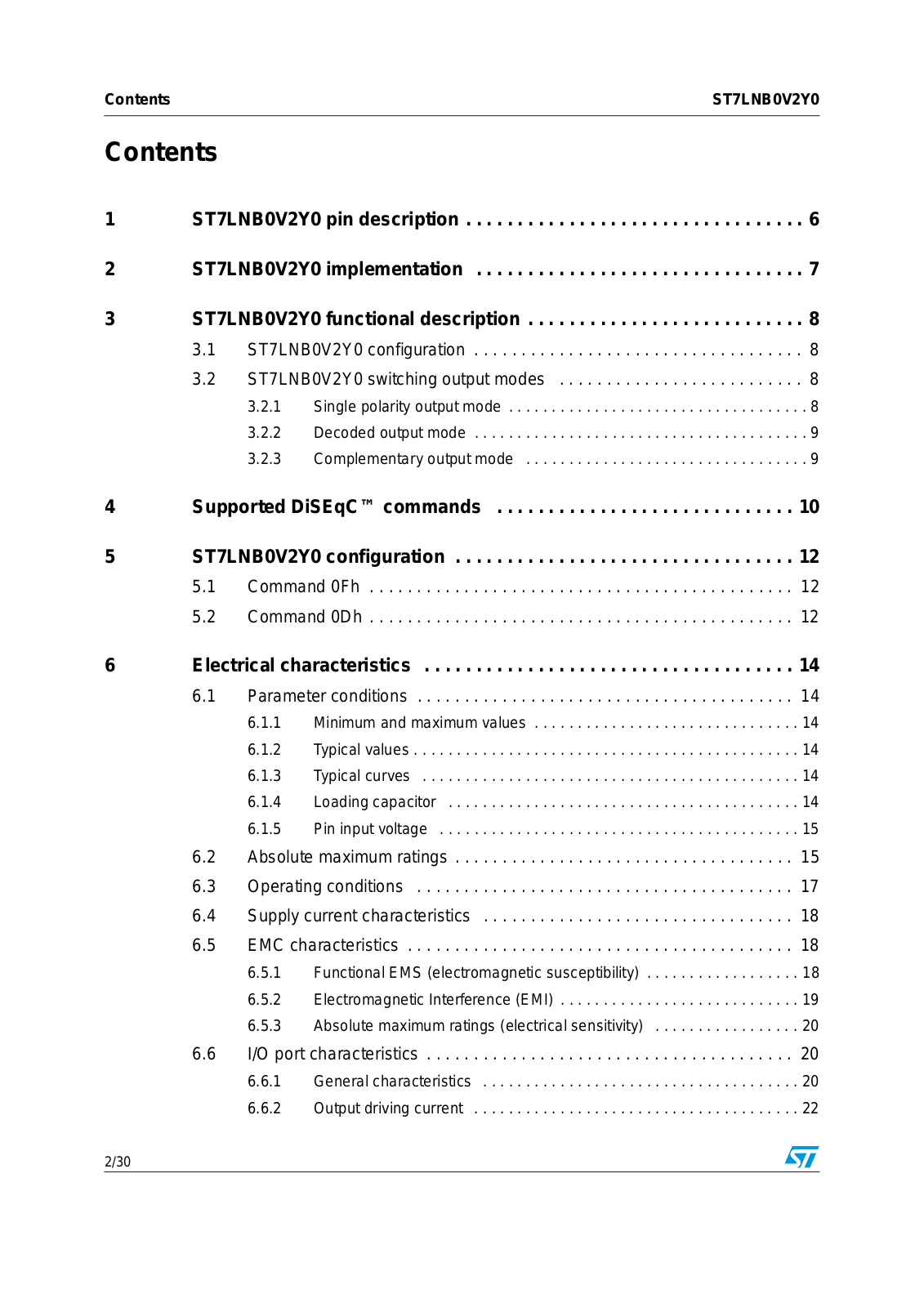
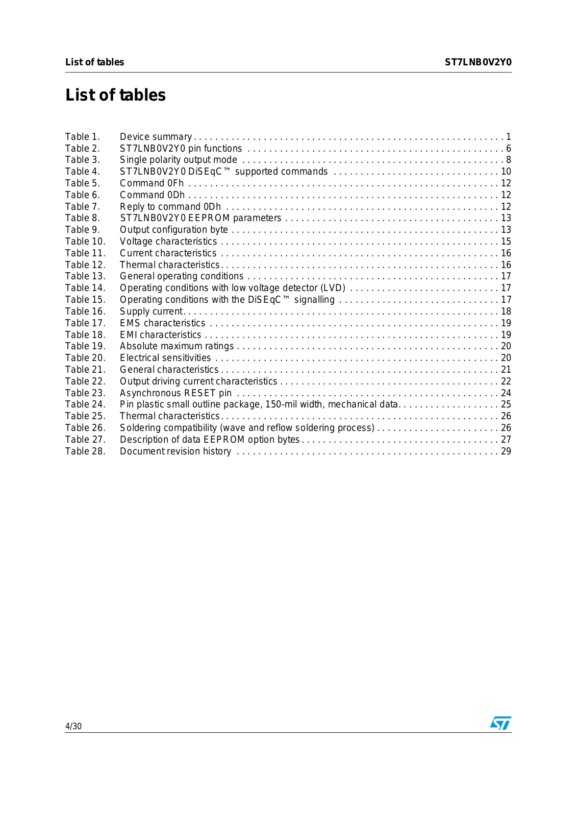
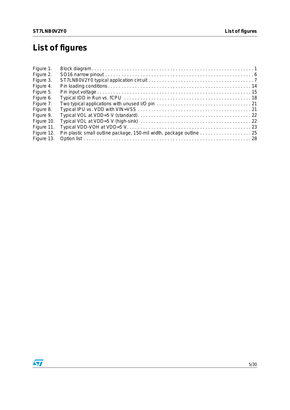
Table of contents
Loading...
ST ST7LNB0V2Y0 User Manual
...
ST User Manual
Download
Specifications and Main Features
Frequently Asked Questions
User Manual
Download
Loading...
+
hidden pages
Unhide
You need points to download manuals.
1 point = 1 manual.
You can buy points or you can get point for every manual you upload.
Buy points
Upload your manuals
 Loading...