


ST70137
UNICORNTMPCI & USB
CONTROLLERLESS ADSL DMT TRANSCEIVER
ST70137 HARDWARE FEATURES
■ SUPPORT DIGITAL SIGNAL PROCESSING
REQUIREMENTS FOR ONE ADSL CPE
CHANEL (ITU-R)
■ COMPLIANT WITH ITU 992.1 (ADSL FULL
RATE) ANNEXE A (ADSL OVER POTS)
AND ANNEXE B (ADSL OVER ISDN) AND
ITU 922.2 (G.LITE) AND ANSI T1.413.
■ DIRECT INTERFACE TO PCI BUS (PCI
RELEASE 2.2 AND COMPLIANT WITH
MICROSOFT PC99 & PC2001 SPECIFICATION)
■ DIRECT INTERFACE TO USB (USB
RELEASE 1.1 SPECIFICATION)
■ DIRECT INTERFACE TO THE EXTERNAL
SERIAL MEMORY TO SUPPORT PCI/USB
USER’S CONFIGURATION
■ DIRECT ANALOG FRONT END INTERFACE
FOR ST70136 OR ST70134
■ 4 TO 8 GPIO DEPENDING ON SELECTED
AFE AND EXTERNAL MEMORY CONFIGURATION USED
DESCRIPTION
ST70137 is STMicroelectronics UNICORN
chipset ADSL DMT transceiver for controllerless
ADSL CPE modem.
UNICORNTMallows to develop easily and quickly
low cost ADSL CPE modem for PC environment.
UNICORNTMis made of two devices, ST70137
and ST70136 or ST70134 (CPE ADSL Analog
Front End). ST70137 provides PCI and USB
interface. PCI is used to build ADSL CPE modem
bundled in the PC, USB interface is used to build
external bus powered ADSL modem.
ST70137 is compliant with ITU 992.1 Annexe A
and B, with ITU 992.2 and with ANSI T1.413.
UNICORNTMchipset is delivered with a complete
PC software suite for Microsoft Windows 98,
Windows 2000 and Windows NT. NDIS5.0 PCI
driver and USB driver with ADSL modem control
and ATM device driver are provided assuring full
ATM support. Configuration and diagnostic tools
are also provided.
UNICORNTMchipset and PC software ensure
interoperability with the most deployed DSLAM.
TM
■ CLOCK & RESET INTERFACE
■ 1.8V AND 3.3V POWER SUPPLY
■ TTL LOGIC LEVELS COMPATIBLE
(DEPENDING ON PADS)
■ POWER MANAGEMENT
■ LOW POWER CONSUMPTION : 0.4W
■ TQFP 144
ST70137 SOFTWARE FEATURES
■ RFC 2364 PPP OVER ATM
■ UNI 3.0, 3.1, 4.0 SIGNALING
■ UBR, CBR
■ AAL0, AAL5
■ NDIS5.0 PCI DRIVER AND USB DRIVER
TQFP144
ORDER CODE: ST70137TQFP
1/22September 2001

TYPICAL APPLICATION
ST70137
PC
BLOCK DIAGRAM
USB_PCIN_sel
PCI
or
USB
ST70137
DMT
Dongle Modem or PCI Board
USB IF PCI_IF MEM IF
USB_BRIDGE PCI_BRIDGE CFG_MEMs
Bridge
SWITCHER
MODEM
USB
ST70136 AFE
or ST70134
ADSL
LINE
I/F
ST70137 ST70136 or ST70134
POTS
Line
TGB
POTS
Line
CFG_SEL
CLK
RST
ATMFIFOs OBC FIFOs REGs PERIPHERAL
UtopFSM OBC_IF
ADSLuP
TOSCAv. 2.0
OBC: On Board Controller
TGB: TimeGeneration Block
TAP: TestAccess Protocol
Utop FSM: Utopia Finite State Machine
GPIO IF
TAP
AFE IF
2/22

ST70137
SOFTWARE ARCHITECTURE
User Applications:
Netscape, NetMeeting, etc.
Control
Modem SWWin32 kernel
Hw Abstraction Layer
USB Driver PCI Driver Registry
USBD SYS - MS Bus Driver
UHCD.SYS OHCD.SYS
Trace Tools
Ring 3:
User Mode
NDIS 5
Data
Ring 0:
Kernel Level
UHCI (Intel) OHCI (NEC and Others)
USB Device PCI Device
Hardware
3/22

PIN CONNECTIONS
D_VSS_PLL
D_VDD_PLL
144143142141 140139138 137 136135 133 132131 130 129 128 127 126 125124 123 122121120 119 118117116 115114113 112 111 110 109
VDD 3.3
1
GPIO[0]
2
GPIO[1]
3
GPIO[2]
4
GPIO[3]
5
VSS
6
DMINUS
7
DPLUS
8
VSS
9
RSTN
10
CFG_SCE
CFG_SDI
VDD 1.8
C_EXT
VSS
VDD 3.3
VR50F
VSS
PCI_CLK
VDD 3.3
VSS
VDD 3.3
PCI[AD29]
VSS
11
12
13
14
15
16
17
18
19
20
21
22
23
24
25
26
27
28
29
30
31
32
33
34
35
36
37 38 39 40 41 42 43 44 45 46 47 48 49 50 51 52 53 54 55 56 57 58 59 60 61 62 63 64 65 66 67 68 69 70 71 72
CFG_SCK/ GPIO[6]
CFG_SD O/GP IO [7]
PCI_INTAN
PCI_RSTN
PCI_GNTN
PCI_REQN
PCI_PMEN
PCI_AD[31]
PCI_AD[30]
PCI_AD[28]
PCI_AD[27]
PCI_AD[26]
A_VSS_PLL
A_VDD_PLL
VSS
TRSTB
TCK
TMS
TDO
TDI
134
ST70137
VDD1.8
VSS
VSS
CTRLDIN/GPIO[4]
CTRLDOUT
AFEWR/GPIO[5]
CLWD
VDD3.3
MCLK
VSS
COMP_ROUT
VDD1.8
AFERXD[3]
AFERXD[2]
AFERXD[1]
AFERXD[0]
VSS
AFETXD[3]
AFETXD[2]
AFETXD[1]
AFETXD[0]
VSS
AFERST
VSS
VSS
VSS
108
VDD3.3
107
ACTD
106
PWDN
105
SUSPENDN
104
SUSPEND
103
LD_PWDN
102
VSS
101
AFESEL
100
USB_PCIN_SEL
99
CFG_MEM_SEL
98
VAUX_D_USB_SP
97
VDD1.8
96
VR50
95
PCI_AD[0]
94
PCI_AD[1]
93
PCI_AD[2]
92
VDD3.3
91
ST70137
90
89
88
87
86
85
84
83
82
81
80
79
78
77
76
75
74
73
PCI_AD[3]
PCI_AD[4]
VSS
PCI_AD[5]
PCI_AD[6]
VDD3.3
PCI_AD[7]
PCI_CBE0N
VSS
PCI_AD[8]
PCI_AD[9]
VDD3.3
PCI_AD[10]
PCI_AD[11]
VSS
PCI_AD[12]
PCI_AD[13]
VDD3.3
PCI_AD[14]
VDD3.3
VSS
PCI_AD[25]
PCI_AD[24]
VDD3.3
PCI_IDSEL
PCI_CBE3N
VSS
PCI_AD[23]
PCI_AD[22]
VDD3.3
PCI_AD[21]
PCI_AD[20]
VSS
PCI_AD[19]
PCI_AD[18]
VDD3.3
PCI_AD[17]
PCI_AD[16]
VDD1.8
PCI_CBE2N
VSS
PCI_IRDYN
PCI_FRAMEN
VDD3.3
PCI_TRDYN
PCI_DEVSELN
VSS
PERRN
PCI_STOPN
SERRN
VDD3.3
PCI_PAR
PCI_CBE1N
VSS
PCI_AD[15]
4/22
ST70137
PIN LIST
PIN NAME TYPE DRIVE DESCRIPTION
1 VDD3.3 P Power supply pins 3.3V for I/O pads (not PCI)
2 GPIO[0] I/O 4mA
3 GPIO[1] I/O 4mA
4 GPIO[2] I/O 4mA
5 GPIO[3] I/O 4mA
6 VSS P Ground
7 DATA_MINUS I/O
8 DATA_PLUS I/O
9 VSS P Ground
10 RSTN I
11 CFG_SCE O 4mA
12 CFG_SCK/GPO[6] O 4mA
13 CFG_SDI I
14 CFG_SDO/GPO[7] O 4mA
15 VDD 1.8 P Power supply pins 1.8V for Core
16 C_EXT P External Capacitor to reduce ripple of the internal DC regulator
17 VSS Ground
18 VDD3.3 P Power supply pins 3.3V for PCI I/O pads ESD protection
19 VR50F P Power Supply for DC regulator (3.3V)
20 PCI_INTAN OD 8mA Low, High Impendance
21 PCI_RSTN I
22 VSS P Ground
23 PCI_CLK I
24 PCI_GNTN I
25 VDD3.3 P Power supply pins 3.3V for PCI I/O pads ESD protection
26 PCI_REQN O 8mA
27 PCI_PMEN OD 8mA
28 VSS P Ground
29 PCI_AD[31] I/O 8mA
30 PCI_AD[30] I/O 8mA
31 VDD3.3 P Power supply pins 3.3V for PCI I/O pads
32 PCI_AD[29] I/O 8mA
33 PCI_AD[28] I/O 8mA
34 VSS P Ground
1
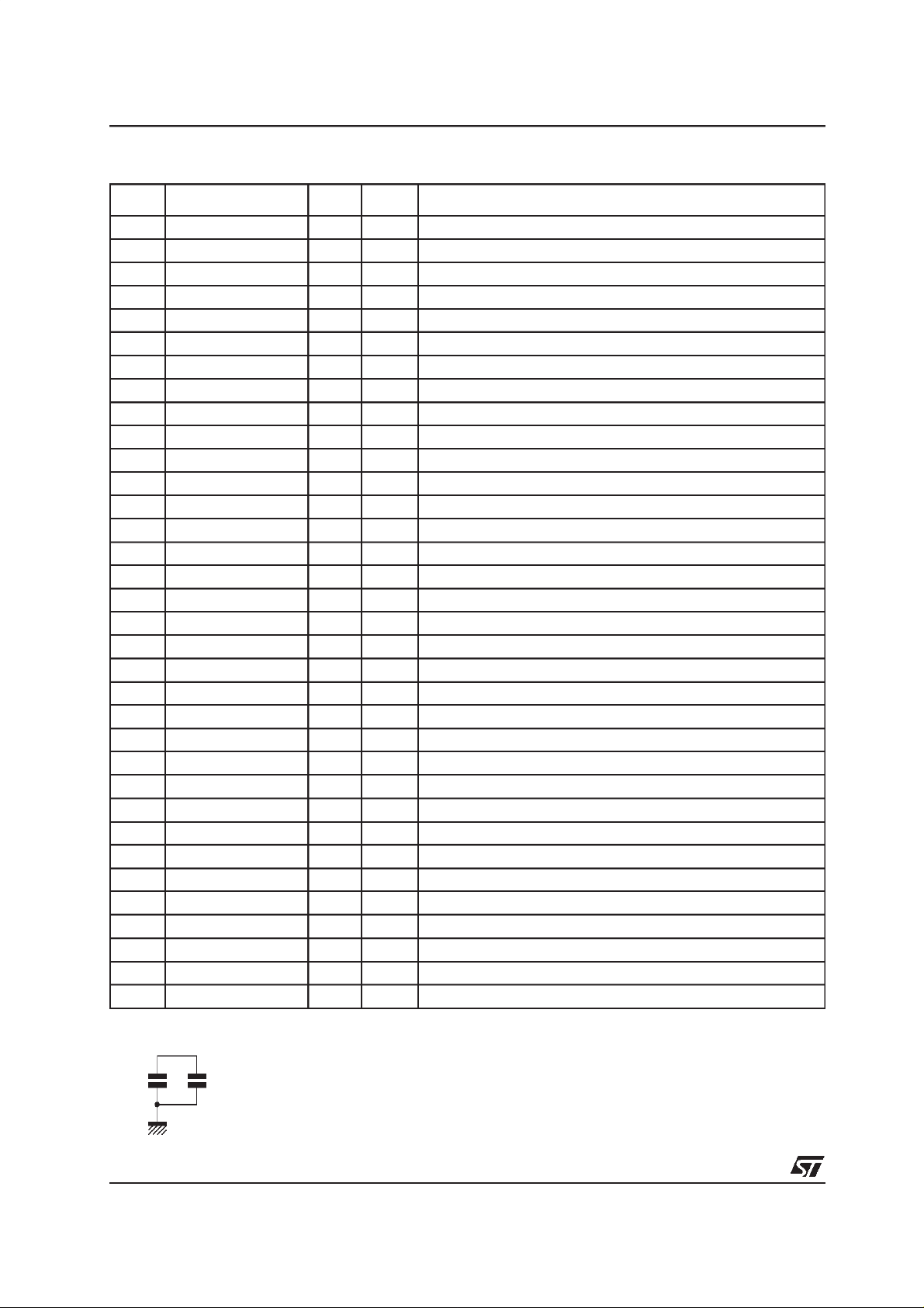
Note 1. Pin C_EXT must be connected:
10nF 1µF
5/22

PIN LIST (continued)
PIN NAME TYPE DRIVE DESCRIPTION
35 PCI_AD[27] I/O 8mA
36 PCI_AD[26] I/O 8mA
37 VDD3.3 P Power supply pins 3.3V for PCI I/O pads ESD Protection
38 PCI_AD[25] I/O 8mA
39 PCI_AD[24] I/O 8mA
40 VSS P Ground
41 PCI_CBE_N[3] I/O 8mA
42 PCI_IDSEL I
43 VDD3.3 P Power supply pins 3.3V for PCI I/O pads ESD Protection
44 PCI_AD[23] I/O 8mA
45 PCI_AD[22] I/O 8mA
46 VSS P Ground
47 PCI_AD[21] I/O 8mA
48 PCI_AD[20] I/O 8mA
49 VDD3.3 P Power supply pins 3.3V for PCI I/O pads ESD Protection
50 PCI_AD[19] I/O 8mA
51 PCI_AD[18] I/O 8mA
52 VSS P Ground
53 PCI_AD[17] I/O 8mA
54 PCI_AD[16] I/O 8mA
55 VDD3.3 P Power supply pins 3.3V for PCI I/O pads
56 VDD1.8 P Power supply pins 1.8V for Core
57 PCI_CBE_N[2] I/O 8mA
58 PCI_FRAMEN I/O 8mA
59 VSS P Ground
60 PCI_IRDYN I/O 8mA
61 PCI_TRDYN I/O 8mA
62 VDD3.3 P Power supply pins 3.3V for PCI I/O pads ESD Protection
63 PCI_DEVSELN I/O 8mA
64 PCI_STOPN I/O 8mA
65 VSS P Ground
66 PCI_PERRN I/O 8mA
67 PCI_SERRN I/O 8mA
68 VDD3.3 P Power supply pins 3.3V for PCI I/O pads ESD Protection
69 PCI_PAR I/O 8mA
70 PCI_CBE_N[1] I/O 8mA
71 VSS P Ground
72 PCI_AD[15] I/O 8mA
73 PCI_AD[14] I/O 8mA
ST70137
6/22

ST70137
PIN LIST (continued)
PIN NAME TYPE DRIVE DESCRIPTION
74 VDD3.3 P Power supply pins 3.3V for PCI I/O pads ESD Protection
75 PCI_AD[13] I/O 8mA
76 PCI_AD[12] I/O 8mA
77 VSS P Ground
78 PCI_AD[11] I/O 8mA
79 PCI_AD[10] I/O 8mA
80 VDD3.3 P Power supply pins 3.3V for PCI I/O pads ESD Protection
81 PCI_AD[9] I/O 8mA
82 PCI_AD[8] I/O 8mA
83 VSS P Ground
84 PCI_CBE_N[0] I/O 8mA
85 PCI_AD[7] I/O 8mA
86 VDD3.3 P Power supply pins 3.3V for PCI I/O pads
87 PCI_AD[6] I/O 8mA
88 PCI_AD[5] I/O 8mA
89 VSS P Ground
90 PCI_AD[4] I/O 8mA
91 PCI_AD[3] I/O 8mA
92 VDD3.3 P Power supply pins 3.3V for PCI I/O pads ESD Protection
93 PCI_AD[2] I/O 8mA
94 PCI_AD[1] I/O 8mA
95 PCI_AD[0] I/O 8mA
96 VR50 P 3.3V Power supply for DC regulator
97 VDD1.8 P Power
98 VAUX_D/USB_SP I
99 CFG_MEM_SEL I
100 USB_PCIN_sel I
101 AFESEL I
102 VSS P Ground
103 LPDWDN O 4mA
104 SUSPEND O 4mA
105 SUSPENDN O 4mA
106 PWDN O 4mA
107 ACTD I
108 VDD3.3 P Power supply pins 3.3V for I/O pads (not PCI)
109 TEST I/O TestReserved - Must be fixed to ground
110 TEST I/O TestReserved - Must be fixed to ground
111 TEST I/O TestReserved - Must be fixed to ground
112 AFERST O 4mA
7/22

PIN LIST (continued)
PIN NAME TYPE DRIVE DESCRIPTION
113 VSS P Ground
114 AFETXD[0] O 8mA
115 AFETXD[1] O 8mA
116 AFETXD[2] O 8mA
117 AFETXD[3] O 8mA
118 VSS P Ground
119 AFERXD[0] I
120 AFERXD[1] I
121 AFERXD[2] I
122 AFERXD[3] I
123 VDD1.8 P Power supply pins 1.8V for Core
124 COMP_CELL O Compensation cell resistor
125 VSS P Ground
126 MCLK I
127 VDD3.3 P Power supply pins 3.3V for I/O pads (not PCI)
128 CLWD I
129 AFEWR/GPIO[5] I/O 4mA
130 CTRLDOUT O 4mA
131 CTRLDIN/GPIO[4] I/O 4mA
132 VSS P Ground
133 TEST I/O TestReserved - Must be fixed to ground
134 VDD1.8 P Power supply pins 1.8V for Core
135 TDI I
136 TDO O 4mA
137 TMS I
138 TCK I
139 TRSTB I
140 VSS P Ground
141 VDD_APLL P PLL Analog power supply 1.8V
142 VSS_APLL P PLL Analog Ground
143 VDD_DPLL P PLL digital power supply 1.8V
144 VSS_DPLL P PLL digital Ground
1
ST70137
Note 1.
COMP_CELL
100KΩ ± 1%
Note: PCI section from pin 16 to pin 96 (included): all the power supply pins (at 3.3V) included in this
section are intentedfor PCI I/O pads.
8/22

ST70137
PIN DESCRIPTION
Signal Name Direction Init Status Polarity Signal Description
PCI INTERFACE
PCI_CLK I - - PCI Clock. (33 MHz)
The rising edge of this signal is the reference upon which
all the other PCI signals are based except for PCI_RSTN
and PCI_INTAN. The maximum PCI_CLK frequency for
ST70137 is 33MHz and the minimum is DC.
PCI_RSTN I I L PCI Reset
Reset bring ST70137 in a known state:
- All PCI bus output signal tri-stated
- All open drain signals floated
- All registers set to their factory defaults
- All FIFOs emptied
- GPIOsignals tri-stated
- Sachem Macrocell initialized
- Clock of Adsl_Up stopped
- AFE set in Power down mode
PCI_REQN O H L PCI Request
This signal is sourced by an agent wishing to become a
bus master. It is a point to point signal and each master
has its own PCI_REQN.
PCI_GNTN I I L PCI Grant
The PCI_GNTN signal is a dedicated, point-to-point signal
provided to each potential bus master and signifies that
access to the bus has been granted.
PCI_AD[31:0] I/O I - PCI Multiplexed Address/Data Bus
Address and data are multiplexed on the same PCI bus
pins. A PCI bus transaction consists of an address phase
followed by the one or more data phase. An address
phase occurs on the PCLK cycle in which PCI_FRAMEN
is asserted. A data phase occurs on PCLK cycles in which
PCI_IRDYN and PCI_TRDYN are both asserted.
9/22

PIN DESCRIPTION (continued)
Signal Name Direction Init Status Polarity Signal Description
PCI_CBE_N[3:0] I/O I L PCI Multiplexed Bus Command Mode
Bus command and byte enables are multiplexed on the
same pins. These pins define the current bus command
during an address phase. During a data phase, these pins
are used as Byte Enables, with PCI_CBE_N[0] (LSB)
enabling byte 0 and PCI_CBE_N[3] enabling byte 3
(MSB).
C/BE[3:0]=Command Type
0000 = Interrupt Acknowledge
0001 = Special Cycle
0010 = I/O Read
0011= I/O Write
0100 = Reserved
0101 = Reserved
0110= Memory Read
0111 = Memory Write
1000 = Reserved
1001 = Reserved
1010 = Configuration Read
1011= Configuration Write
1100 = Memory Read Multiple
1101 = Memory Write Multiple
1110 = Memory Read line
1111 = Memory Write and Invalidate
PCI_PAR I/O I H PCI Parity (even)
Parity is always driven as even from all PCI_AD[31:0] and
PCI_CBE[3:0] signals. The parity is valid during the clock
following the address phase and is driven by the bus master. During a data phase for write transactions, the bus
master sources this signal on the clock following
PCI_IRDYN active; during data phase for read transactions, this signal is driven by the target and is valid on the
clock following PCI_TRDYN active. The PCI_PAR signal
has the same timing as PCI_AD[], delayed by one clock.
PCI_FRAMEN I/O I L PCI Cycle Frame
This signal is driven by current bus master to indicate the
beginning and duration of a bus transaction. When
PCI_FRAMEN is first asserted, it indicates a bus transaction is beginning with a valid addresses and bus command present on PCI_AD[31:0] and PCI_CBE[3:0]. Data
transfer continue until PCI_FRAMEN is asserted.
PCI_FRAMEN de-assertion indicates the transaction is in
final data phase or has completed.
PCI_DEVSELN I/O I L PCI Device Select
This signal is driven by a target decoding and recognizing
its bus address. This signal informs a bus master whether
an agent has decoded a current bus cycle.
PCI_IRDYN I/O I L PCI Initiator Ready
This signal is always driven by the bus master to indicate
its ability to complete the current data phase. During write
transactions it indicates PCI_AD[] contains valid data.
PCI_IDSEL I I H PCI Initialization Device Select
This pin is used as chip select during configuration read
or write transactions.
ST70137
10/22

ST70137
PIN DESCRIPTION (continued)
Signal Name Direction Init Status Polarity Signal Description
PCI_TRDYN I/O I L PCI Target Ready
This signal is driven bythe select target to indicate the target is able to complete the current data phase. During
read transactions, it indicates PCI_AD[] contains valid
data. Wait states occur until both PCI_TRDYN and
PCI_IRDYN are asserted togheter.
PCI_PERRN I/O I L PCI Parity Error
Only for reporting data parity errors for all bus transactions
except for special cycles. It is drivenby the agent receiving
data two clock cycles after the parity was detected as an
error. This signal is driven inactive (high) for one clock
cycle prior to returning to the tri-state condition.
PCI_SERRN O Z L PCI System Error
Used to report address and data parity errors on special
cycle commands and any other error condition having a
catastrophic system impact.
PCI_INTAN O Z L PCI Interrupt A
This signal is defined as optional and level sensitive. Driving it low will interrupt to the host. The PCI_INTAN interrupt is to be used for any single function device requiring
an interrupt capability.
PCI_PMEN O Z L PCI Power Management Event
This signal is used to indicate that a power management
event has been detected. The PCI_PMEN signal is asynchronous with respect to the PCI clock; it is set (if
enabled) by the low to high transition of the ACTD signal.
PCI_STOPN I/O I L PCI Stop
This signal indicates the current target is requesting the
master to stop the current transaction.
USB INTERFACE
DPLUS I/O I + Differential positive USB data input/output.
DMINUS I/O I - Differential negative USB data input/output.
MISCELLANEOUS INTERFACE
GPIO[3:0] I/O I - General Purpose I/O Bus
These signals are controlled by internal registers located
inside ADSL uP block. At the Power-up, Hardware or
Software Reset the input direction is chosen.
CFG_MEM_SEL I I - Select Internal [1] or External [0] PCI/USB configuration
memory.
USB_PCIN_sel I I - Select PCI [0] or USB [1] Interface
Selecting USB interface and if all Test Pins are set to
default value, all the PCI Pads are deactivated. The
power supply for this section can be not provided. The
PCI section is frozen.
Selecting PCI interface the DMINUS and DPLUS has to be
set to the low level(reset mode).The PLL is in powerdown
and no any clockwill be providedto the USB section.
VAUX_D / USB_SP I I - VAUX Detect when USB_PCIN_sel = [0] or USB SELF
POWERED when USB_PCIN_sel = [1].
11/22

ST70137
PIN DESCRIPTION (continued)
Signal Name Direction Init Status Polarity Signal Description
CLOCK & RESET INTERFACE
MCLK I I - 35.328 MHz Master Input Clock.
RSTN I I L Asynchronous Master Input Reset (active if
AFE INTERFACE
AFETXD[3:0] O L - AFE Transmit Data Nibble Bus
AFERXD[3:0] I I - AFE Receive Data Nibble Bus
CLWD I I H Start of word indication
CTRLDOUT O H L Transmit Control Word Data to AFE
AFESEL I I - Select ST-70136 [0] or ADSL_C [1].
AFERST O L L AFE Reset
AFEWR / GPIO[5] I/O I L/- AFE Write control outputsignal (AFESEL = 0), or Gen-
CTRLDIN / GPIO[4] I I L/- Receive Control word data from AFE (AFESEL = 0), or
SUSPEND O L H Suspend Mode Indication.
SUSPENDN O H L Suspend Mode Indication Negated.
PWDN O H H AFE Power Down.
LDPWDN O H H Line Driver Power Down [1].
USB_PCI_SEL = ‘1’).
The signal changes are synchronized to the rising edge of
MCLK clock signal.
The signal changes are synchronized to the rising edge of
MCLK clock signal.
This signal is the word clock used to enable shift of data.
It occurs on CTRLDOUT signal to indicate the first data of
the nibble sequence. The CLWD frequency is equal to
MCLK/4.
The data is shifted out from internal register on the rising
edge of MCLK during CLWDassertion.
This signal is connected to the internal PCFW
(USB_PCIN_SEL = [0]) or UCFW registers
(USB_PCIN_SEL = [1]) if AFESEL = [0], or to the Sachem
GPOUT register if AFESEL = [1]. Not usable in USB
mode.
eral Purpose I/O pin. The selection is performed writing
the proper bit in the PCFW or UCFW (depending on status of USB_PCIN_SEL pin) registers. At the power-on or
hardware reset the GPIO[5] function is selected.
General Purpose I/O pin. The selection is performed writing the proper bit in the PCFW or UCFW (depending on
status of USB_PCIN_SEL pin) registers. At the power-on
or hardware reset the GPIO[4] function is selected ACTD I
I H Activation Tone Detect [1] (or Wake Up signal).
When PCI IF has been selected, the Low to High transition of ACTD asserts the PCI_PMEN signal (if this last
has been enabled) and generates an interrupt event.
When USB IF has been selected, the Low to High transition of ACTD de-asserts the SUSPEND signal and
re-enable the internal ST70137 activity.
12/22

ST70137
PIN DESCRIPTION (continued)
Signal Name Direction Init Status Polarity Signal Description
CFG_MEM INTERFACE
CFG_SCE O L H Chip Enable
This pin is designed to directly interface to a serial
EEPROM that use the 93C66 EEPROM interface protocol. This pin has to be connected directly to the
EEPROM’s chip select pin.
CFG_SCK/GPO[6] O L - Serial Clock or General Purpose Output Pin 6 depending
on the internal selection. The selection is performed writing the proper bit inside the PCFW or UCFW register. At
the power-on or hardware reset the CFG_CLK functionality is selected. This pin is designed to directly interface to
a serial EEPROM that use the 93C66 EEPROM interface
protocol.
CFG_SDI I I H Serial Data Input
Data going into this pin has to be generated on the rising
edge of CFG_SCK. This pin is designed to directly interface to a serial EEPROM that use the 93C66 EEPROM
interface protocol.
CFG_SDO/GPO[7] O L - Serial Data/Address Output
General Purpose Output Pin 7 depending on the internal
selection. The selection is performed writing the proper bit
inside the PCFW or UCFW register. At the power-up or
hardware reset the CFG_SDO functionality is selected.
The CFG_SDO data change is synchronous with the falling edge of CFG_SCK. This pin is designed to directly
interface to a serial EEPROM that use the 93C66
EEPROM interface protocol.
JTAG INTERFACE
TDI I IH - JTAG TestData Input.
TDO O - - JTAG TestData Output.
TMS I IH L JTAG TestMode Select.
TCK I IL - JTAG TestClock.
TRSTB I IL L JTAG Reset (active Low).
TEST CONDITION
All Ouputs have been loaded with.
Outputs Minimum Maximum Unit
PCI 0 50 pF
USB * 0 50 pF
Others 0 15 pF
* See text scheme at page 20.
13/22

ST70137
TIMING SPECIFICATION
MCLK Master Clock
Symbol Parameter Minimum Typical Maximum Unit
F Clock frequency 35.328 MHz
T Clock Period 28.3 ns
Th Clock Duty cycle 40 60 %
AFE IF Transmit& Receive Signals
MCLK
AFERXD
AFETXD
CLWD
CTRLDO UT
AFEWR
CTRLDIN
Ts3
Tv1
Tv2
Ts1
Tv3
T
Th1
Th2
Ts2
Th3
AFE IF Transmit & Receive signals
Ts1 Data Setup Time 5 ns
Th1 Data Hold Time 7 ns
Tv1 Data Valid Time 13 ns
Ts2 Data Setup Time 5 ns
Th2 Data Hold Time 6 ns
Tv2 Data Valid Time 18 ns
Ts3 Data Setup Time 20 ns
Th3 Data Hold Time 1 ns
Tv3 Data Valid Time 18 ns
14/22

ST70137
CFG_MEM IF Signals with PCI = 30.3ns
CFG_SCK
CFG_SDO
Tsclk
Th
CFG_SDI
Ts
CFG_SCE
Tv2
Tv1
CFG_MEM IF signals with PCI = 30.3ns *
Symbol Parameter Minimum Typical Maximum Unit
Ts Data Setup Time 45 ns
Th Data Hold Time 0 ns
Tv1 Data Valid Time 970 ns
Tv2 Data Valid Time 160 ns
Tsck SCK Clock period: - USB 48MHz USB_CLK / 64 ns
- PCI 33MHz PCI_CLK / 64
* PCI conditions are more restrictive than USB conditions.
GPIO IF
PCI_CLK
Tv
GPIOOUTPUT
GPIO IF
Symbol Parameter Minimum Typical Maximum Unit
Tv Output Data Valid from PCI_CLK 22 ns
15/22

ST70137
ELECTRICAL SPECIFICATIONS
Absolute Maximum Ratings
Parameter Description Minimum Typical Maximum Units
3.3 Supply Voltage 3.0 3.3 3.6 V
V
DD
1.8 Supply Voltage 1.62 1.8 1.98 V
V
DD
Ptot TotalPower Dissipation 450 mW
Tamb Ambient Temperature 1.5ml airflow 0 70 °C
Tstg Storage Temperature
V
ESD
ESD Protection (HBM) 2000 V
PCI Interface DC Specifications
Parameter Description Condition Minimum Typical Maximum Units
-65 +150 °C
Vilp Input LOW Voltage -0.5 0.3V
Vihp Input HIGH Voltage 0.5V
lip Input Leakage Current 0<Vin<V
DD
DD
-10 10 µA
Volp Output LOW Voltage Iout = 1.5mA 0.1V
Vohp Output HIGHT Voltage Iout = 0.5mA 0.9V
DD
DD
VDD+0.5 V
DD
Cinp Input Pin Capacitance * 10 pF
Cclkp CLK Pin Capacitance * 5 12 pF
Cidsel IDSEL Pin Capacitance * 8 pF
Lpinp Pin Inductance * N/A 20 nH
* Guaranted by design.
USB Interface DC Specifications
Nominal DC Characteristics (DPLUS, DMINUS)
Parameter Description Minimum Typical Maximum Units
V
DI
V
CM
V
SE
V
OH
V
OL
I
LO
C
IN
R
* Guaranted by design.
Differential Input Sensitivity [(D+) - (D-)] 0.2 V
Differential Common Mode Range 0.8 2.5 V
Single Ended Receiver Threshold 0.8 2 V
High Level Output Static Voltage (RL of 15KΩ to GND
2.8 3.6
Low Level Output Static Voltage (RL of 1.5KΩ to 3.6V)
Hi-Z StateDataLineLeakage Current(0V < Vin < 3.3V) 30 µA
Transceiver Capacitance (Pin to GND) * 10 pF
Driver Output Resistance (steady state drive) 28 44 Ω
D
0.3
V
V
V
V
V
16/22

ST70137
Other Signals DC Characteristics
The values presented in the following table apply for all inputs and/or outputs unless otherwise specified.
All voltages are referenced to VSS, unless otherwise specified, positive current is towards the device.
Symbol Parameter Test Condition Minimum Typical Maximum Units
Input Leakage Current Vin = V
I
IN
I
I
I
Tristate Leakage Current Vin = V
OZ
Pull Up Current Vin =V
PU
Pull Down Current Vin =V
PD
SS,VDD
SS,VDD
SS
DD
no pull up/pull down -4 +4 µA
no pull up/pull down -4 +4 µA
-15 -40 -125 µA
+15 +30 +125 µA
Suspend Mode Current Consumption
Symbol Parameter Test Condition Minimum Typical Maximum Units
I
I
Suspend Mode Current
518
Consumption on 1.8V
Suspend Mode Current
533
Consumption on 3.3V
Temperature= 25°C 350 µA
Temperature= 25°C 150 µA
AC Specifications
PCI Signaling AC Specifications
Symbol Parameter Test Condition Minimum Typical Maximum Units
Ioh Switching Current High 0 < Vout ≤ 0.3V
Vout = 0.7V
Iol Switching Current Low V
> Vout ≥ 0.6V
DD
Vout = 0.18V
DD
DD
DD
DD
Icl Low Clamp Current * -3 < Vin ≤ -1V -25 + (Vin + 1)
Ich High Clamp Current * V
Tr Unloaded Output Rise Time * 0.2V
Tf Unloaded Output Fall Time * 0.6V
* Guaranted by design.
+4 > Vin ≥ VDD+ 1 25 +(Vin - VDD-1)
DD
to 0.6V
DD
DD
to 0.2V
DD
DD
-12V
DD
-32V
DD
16V
DD
38V
DD
/ 0.015
/ 0.015
1 4 V/ns
1 4 V/ns
mA
mA
mA
mA
mA
mA
Timing Specifications
PCI Clock Specifications
Symbol Parameter Test Condition Minimum Typical Maximum Units
Tc Clock Cycle Time 30 50 ns
Th Clock High Time 11 ns
TI Clock Low Time 11 ns
Clock Slew Rate * 1 4 V/ns
* Guaranted by design.
17/22

PCI Clock Waveform 5V
2.0V
1.5V
0.8V
PCI Clock Waveform 3.3V
0.5V
DD
0.4V
DD
0.3V
DD
2.4V
Th TI
Tc
0.6V
DD
0.4V
0.2V
ST70137
DD
Th TI
Tc
PCI Timings
Symbol Parameter Minimum Typical Maximum Units
Tval Clock to Signal Valid Delay (bused signals) 2 11 ns
Tval(ptp) Clock to Signal Valid Delay (point to point) 2 12 ns
Ton Float to Active Delay 2 ns
Toff Active to Float Delay 28 ns
Tsu Input Set up Time to Clock (bused signals) 7 ns
Tsu(ptp) Input Set up Time to Clock (point to point) * 10, 12 * ns
Th Input Hold Time from Clock 0 ns
Trst Reset Active Time after Power Stable 1 ms
Trst-clk Reset Active Time after CLK Stable ** 100 µs
Trst-off Reset Active to Output Float Delay ** 40 ns
* PCI REQN and GNTN are point-to-point signals and have different output valid delay and input setupt times than do bused signals. REQN
has set up of 12ns and GNTN of 10ns. All other signals are bused.
** Guaranted by design.
18/22

ST70137
CLK
Input
Output
Tri-stateOutput
Ton
USB Interface AC Specifications (1.1 version)
AC Characteristics (D+, D-)
Tsu
Th
Tval
Toff
Symbol Parameter Test Condition Minimum Typical Maximum Units
t
V
Average bit rate (12 M/s ±0.05%) 11.97 12.03 Mbps
DR
Rise Time between 10% and 90% (see
t
R
Figure Rise and Fall Time Measures)
Fall Time 10% and 90% (see Figure Rise
t
F
and Fall Time Measures)
Output Signal Crossover Voltage 1.3 2 V
CRS
420ns
420ns
USB TestScheme
Test
2
Test
1
50pF 50pF
19/22

Rise and Fall Time Measures
ST70137
T
R
90%
10% 10%
90%
T
F
Input / Output TTL Generic Characteristics
The value presented in the following table apply for all TTL inputs and/or outputs unless otherwise
specified.
Symbol Parameter Test Condition Minimum Typical Maximum Units
V
V
V
V
IHHY
V
V
V
* Guaranted by design.
Low Level Input Voltage 0.8 V
IL
High Level Input Voltage 2.0 V
IH
Low Level Threshold, falling * Slow edge < 1V/µs 0.9 1.35 V
ILHY
Low Level Threshold, rising * Slow edge < 1V/µs 1.3 1.9 V
Schmitt Trigger Hysteresis * Slow edge < 1Vµs 0.4 0.7 V
HY
Low Level Output Voltage I
OL
High Level Output Voltage I
OH
= XmA (see Note) 0.4 V
OUT
= XmA (see Note) 2.4 V
OUT
Note: The reference current is dependent on the exact buffer chosen and is a part of the buffer name.
The available values are 2, 4 and 8mA.
20/22

ST70137
PACKAGE MECHANICAL DATA (TQFP144 - 20 x 20 x 1.40 mm)
144 109
1
36 73
e
108
E3
E1
0,076 mm
0.03 inch
SEATING PLANE
E
A
A2
A1
B
37 72
D3
D1
D
L1
L
0,25 mm
.010 inch
GAGE PLANE
K
c
Millimeters Inches
Dimension
Minimum Typical Maximum Minimum Typical Maximum
A 1.60 0.063
A1 0.05 0.15 0.002 0.006
A2 1.35 1.40 1.45 0.053 0.055 0.057
B 0.17 0.22 0.27 0.0067 0.0087 0.011
C 0.09 0.20 0.0035 0.008
D 22.00 0.866
D1 20.00 0.787
D3 17.50 0.689
e 0.50 0.020
E 22.00 0.866
E1 20.00 0.787
E3 17.50 0.689
L 0.45 0.60 0.75 0.018 0.024 0.030
L1 1.00 0.039
K0°(Min.), 7° (Max.)
21/22

ST70137
Information furnished is believed to be accurate and reliable. However, STMicroelectronics assumes no responsibility for the
consequences of use of such information nor for any infringe mentof patents or other rights of third parties which may resultfrom
its use. No license is granted by implication or otherwise under any patent or patent rights of STMicroelectronics. Specifications
mentioned in this publication are subject to change without notice. This publication supersedes and replaces all information
previously supplied. STMicroelectronics products are not authori zed for use as critical components in life support devices or
systems without express written approval of STMicroelectronics.
The ST logo is a registered trademark of STMicroelectronics
2001 STMicroelectronics - All Rights Reserved
STMicroelectronics GROUP OF COMPANIES
Australia - Brazil - Canada - China - Finland - France - Germany - Hong Kong - India - Israel - Italy - Japan - Malaysia - Malta - Morocco
Singapore - Spain - Sweden - Switzerland - United Kingdom - United States
http://www.st.com
22/22
ST70137.PDF
 Loading...