

ST33TPM12LPC
TSSOP28
VQFN32
Trusted Platform Module with
LPC interface based on 32-bit ARM® SecurCore® SC300™ CPU
Data brief
Features
TPM features
■ Single-chip Trusted Platform Module (TPM)
■ Compliant with Trusted Computing Group
(TCG) Trusted Platform Module (TPM) Main
specifications 1.2, Level 2, Revision 116
■ Compliant with TCG PC Client Specific TPM
Interface Specifications 1.21
■ Targeting security certification based on
certified TPM Protection Profile (Revision 116)
with Evaluation Assurance Level (EAL) 4+
■ 33-MHz Low Pin Count (LPC) interface V1.1
■ Provisioned with Endorsement key and
Endorsement Key certificate
■ Support of clock suspension for power saving
mode
■ Support of Field Upgrade and Dictionary Attack
protection
■ Monotonic counter endurance guaranteed for
7 years
■ Support of software and hardware physical
presence
Hardware features
■ ARM® SecurCore® SC300™ 32-bit RISC core
■ Highly reliable CMOS EEPROM submicron
technology
– 30-year data retention at 25° C
– 500,000 Erase/Write cycles endurance
typical at 25° C
■ Temperature range: 0°C to +70°C
■ ESD protection up to 4 kV (HBM)
■ 3.3 V supply voltage range
■ 28-lead thin shrink small outline and 32-lead
very thin fine pitch quad flat pack ECOPACK®
packages
Security features
■ Active shield and environmental sensors
■ Memory protection unit (MPU)
■ Monitoring of environmental parameters
(power and clock)
■ Hardware and software protection against fault
injection
■ AIS-31 Class P2 compliant true random
number generator (TRNG)
■ Cryptographic algorithms:
– RSA key generation from 512 to 2048 with
a 2-byte step
– RSA signature and encryption
– SHA-1 and SHA-256
– AES-128 in CTR mode
Performance and resource features
■ SHA1 computation for 64-byte block: 155 µs
■ Signature with a 2048-bit key: 150 ms
■
Signature with a 1024-bit key: 30 ms
■
NV storage allocated space: 4 Kbytes
(1.2 Kbytes used by EK certificate)
■ Supported 2048-bit key slots:
– up to 10 key slots (without EK and SRK)
– 1 key slot in volatile memory for high
frequency loading use case
a. Typical value with clock configuration in secure mode
without communication time.
(a)
(a)
(a)
December 2011 Doc ID 022203 Rev 2 1/11
For further information contact your local STMicroelectronics sales office.
www.st.com
11

Description ST33TPM12LPC
1 Description
The ST33TPM12LPC is a cost-effective and high performance Trusted Platform Module
(TPM).
This device implements the functions defined by the Trusted Computing Group
(www.trustedcomputinggroup.org) in the TCG Trusted Platform Module Specifications
version 1.2 Level 2 Revision 116, the TCG PC Client specific TPM interface specifications
1.21 and the PC Client implementation specification for conventional BIOS.
The ST33TPM12LPC is based on a secure MCU hardware platform.
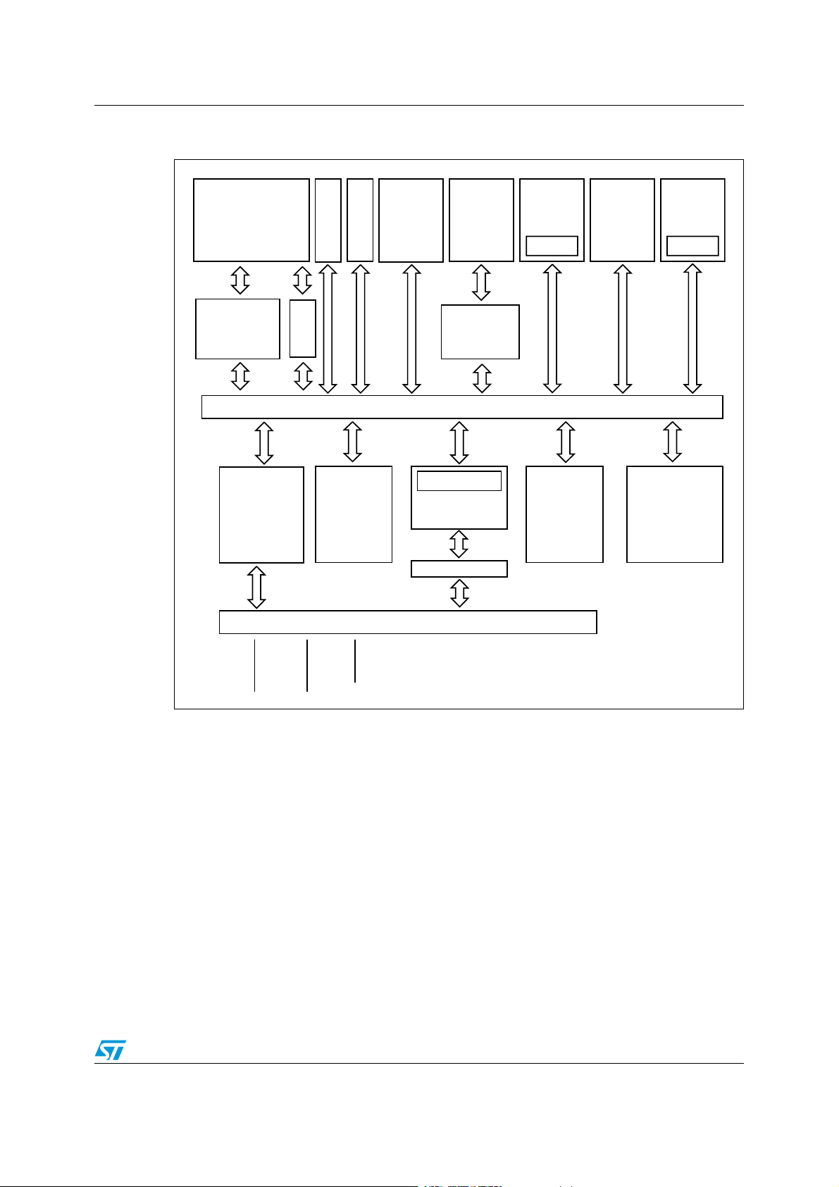
The ST33TPM12LPC is built on a 32-bit ARM® reduced instruction set computing (RISC)
processor which provides high cryptographic and general performances. A crypto-processor
NESCRYPT is also present to support efficiently all public key cryptographic algorithms.
1.1 Hardware features
The ST33TPM12LPC is based on a smartcard-class secure MCU that incorporates the
most recent generation of ARM processors for embedded secure systems. Its SecurCore®
SC300™ 32-bit RISC core is built on the Cortex™ M3 core with additional security features
to help to protect against advanced forms of attacks.
Cadenced at 30 MHz, the SC300™ core brings great performance and excellent code
density thanks to the Thumb®-2 instruction set.
The ST33TPM12LPC offers an LPC (Low Pin Count) communication interface compatible
with Low Pin Count interface specification v1.1.
Three general purpose 16-bit timers are available; one configurable as a watchdog. An
additional 24-bit timer is available in the CPU cadenced with the CPU clock.
The ST33TPM12LPC features hardware accelerators for advanced cryptographic functions.
The EDES peripheral provides a secure DES (Data Encryption Standard) algorithm
implementation, while the NESCRYPT crypto-processor efficiently supports the public key
algorithm.
The ST33TPM12LPC operates in the 0 to +70°C temperature and 3.3V supply voltage
ranges.
In order to meet environmental requirements, ST offers these devices in different grades of
ECOPACK® packages, depending on their level of environmental compliance. ECOPACK®
specifications, grade definitions and device status are available at: www.st.com.
ECOPACK® is an ST trademark.
2/11 Doc ID 022203 Rev 2
ST33TPM12LPC Description
Figure 1. ST33TPM12LPC block diagram
!2-¤
3ECUR#ORE¤
3##05
#ODE$ATA
3IGNATURE
#LOCK
'ENERATOR
-ODULE
-05
2!-
%%02/-
#2#
-ODULE
5SER
2/-
342/-
"OOT
SOFTWARE
342/-
&IREWALL
!("!0")NTERNAL"US
)/"UFFER
4)3%NGINE
,0#
%$%3
!CCEL
ERATOR
2!-
4HREE
BIT
TIMERS
3ECURITY
-ONITOR
INGAND
#ONTROL
.%3
#2904
2!-
4RUE
2ANDOM
.UMBER
'ENERATOR
,2%3%4
-ULTIPLEXED)/S
,&2!-%
,0#0$
,!$;=
,#,+
3%2)21
00
-36
Doc ID 022203 Rev 2 3/11
Pin and signal description ST33TPM12LPC
1
2
3
4
5
6
7
8
9
10
11
12
13
14
28
27
26
25
24
23
22
21
20
19
18
17
16
15
NC
NC
NC
GND
NC
NC
PP
VNC
VNC
VPS
GND
NC
NC
NC
LPCPD
SERIRQ
LAD0
NC
VPS
LAD1
LFRAME
LCLK
LAD2
NC
NC
LRESET
GND
LAD3
TSSOP28
1
2
3
4
5
6
7
8
9 1011121314
28 27 26 25
24
23
22
21
20
19
18
17
1615
GND
NC
NC
NC
NC
PP
VNC
VNC
VPS
GND
NCNCNC
LPCPD
SERIRQ
LAD0NCVPS
LAD1
LFRAME
LCLK
LAD2
NC
NC
LRESET
GND
LAD3
QFN32
29303132
NC
NC
NC
NC
NC
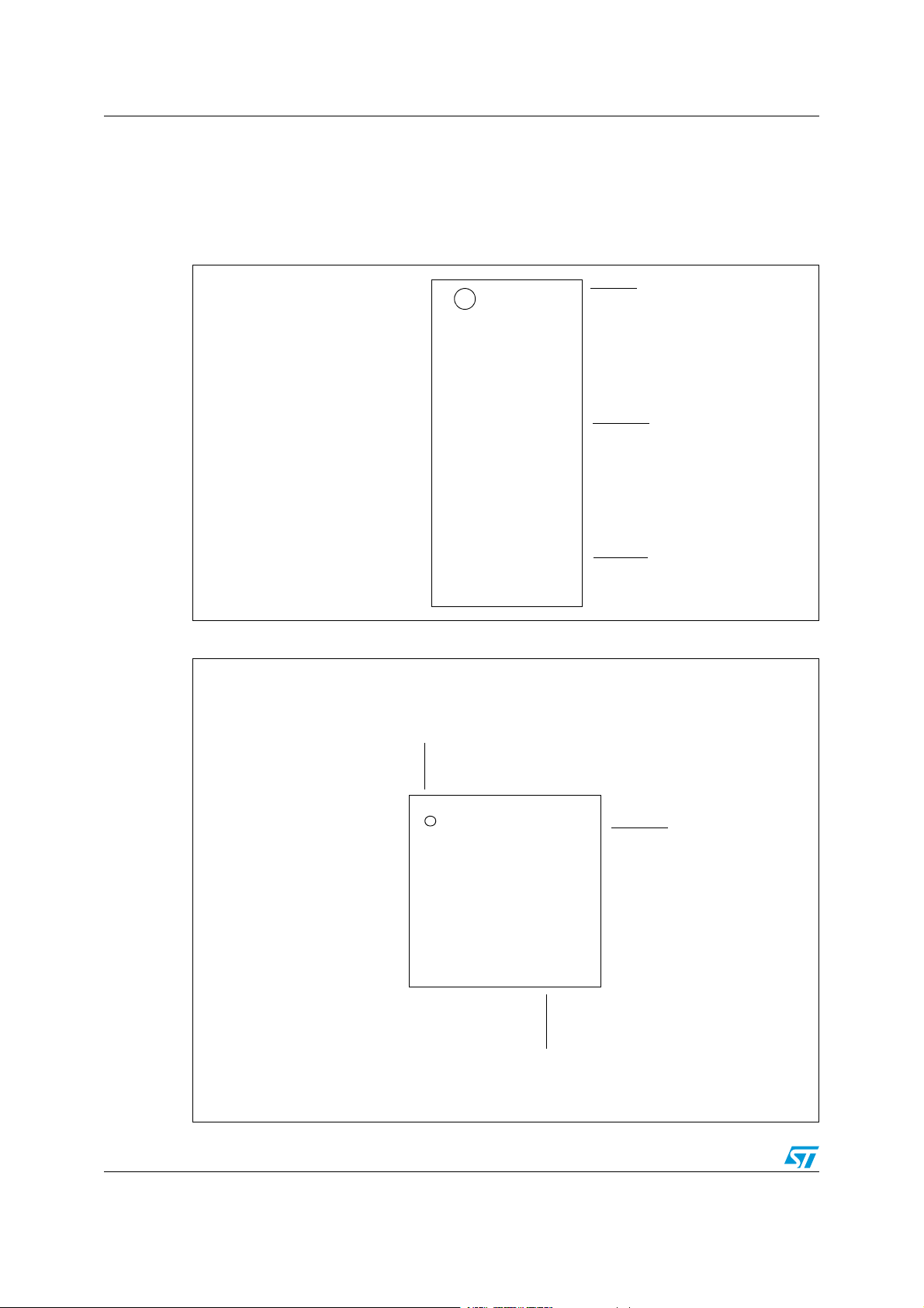
2 Pin and signal description
2.1 Pinout descriptions
Figure 2. TSSOP28 pinout
Figure 3. QFN32 pinout
4/11 Doc ID 022203 Rev 2
ST33TPM12LPC Pin and signal description
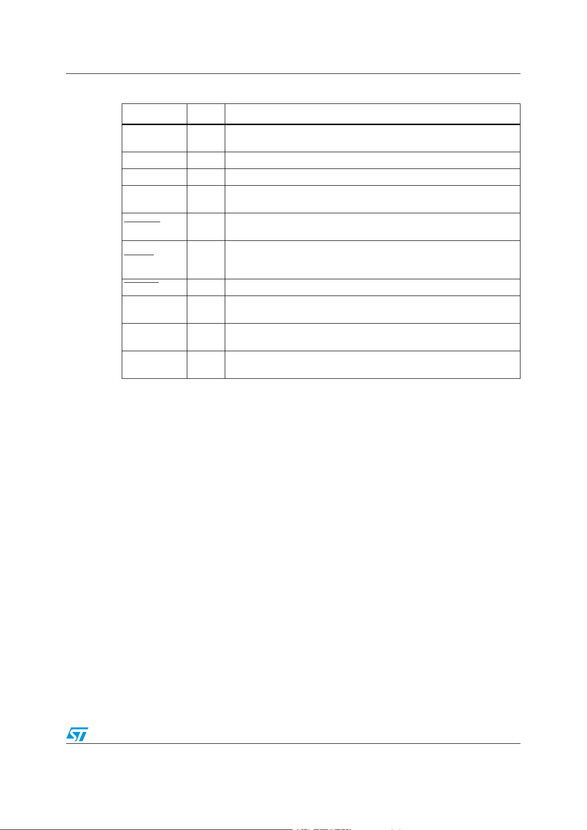
Table 1. Pin descriptions
Signal Type Description
VPS Input
3.3V Power supply. This pin must be connected to 3.3V DC power rail
supplied by the motherboard.
GND Input GND has to be connected to the main motherboard ground.
LAD[3:0] Bidir LPC Multiplexed Command, Address and Data (see LPC Spec).
LCLK Input
LFRAME Input
LPC Clock Same 33-MHz clock as PCI clock on the host. Same clock
phase with typical PCI skew. (see LPC Spec).
LPC Frame indicates start of a new cycle, termination of broken cycle (see
LPC Spec).
LPC Power Down indicates that the peripheral should prepare for power
LPCPD
Input
to be removed from the LPC i/F devices. Actual power removal is system
dependent (see LPC Spec).
LRESET
PP Input
SERIRQ Bidir
VNC -
Input LPC Reset used to re-initialize the device.
Physical Presence, active high, internal pull-down. Used to indicate
Physical Presence to the TPM.
Serialized IRQ is used by TPM to handle interrupt support (see Serialized
IRQ support for PCI systems).
Vendor-controlled No Connect: internal pull-up implemented. Can be left
unconnected. Must not be tied to GND.
Doc ID 022203 Rev 2 5/11

Package mechanical data ST33TPM12LPC
3 Package mechanical data
In order to meet environmental requirements, ST offers these devices in different grades of
ECOPACK
specifications, grade definitions and product status are available at: www.st.com.
ECOPACK
®
packages, depending on their level of environmental compliance. ECOPACK®
®
is an ST trademark.
28-pin thin shrink small outline package (TSSOP) with 4.4-mm body width
Dimensional features of the TSSOP28 package: Body width 4.4 mm. Pitch 0.65 mm.
Unless otherwise specified, general tolerance is ± 0.1 mm.
Figure 4. 28-lead thin shrink small outline package outline
Table 2. 28-lead thin shrink small outline package mechanical data
Symbol
Min. Typ. Max. Min. Typ. Max.
A1.200.047
A1 0.05 0.15 0.002 0.006
A2 0.80 1.00 1.05 0.031 0.040 0.041
b 0.19 0.30 0.007 0.012
c 0.09 0.20 0.004 0.008
D 9.60 9.70 9.80 0.378 0.382 0.386
E 6.20 6.40 6.60 0.244 0.252 0.260
E1 4.30 4.40 4.50 0.170 0.173 0.177
e 0.65 0.026
6/11 Doc ID 022203 Rev 2
millimeters inches

ST33TPM12LPC Package mechanical data
Table 2. 28-lead thin shrink small outline package mechanical data (continued)
Symbol
Min. Typ. Max. Min. Typ. Max.
L 0.45 0.60 0.75 0.018 0.024 0.0230
L1 1.00 0.040
k0° 8°0° 8°
aaa 0.10 0.004
millimeters inches
Doc ID 022203 Rev 2 7/11

Package mechanical data ST33TPM12LPC
Seating plane
ddd C
C
A3
A1
A
D
e
9
16
17
24
32
Pin # 1 ID
R = 0.30
8
E
L
L
D2
1
b
E2
42_ME
Bottom view
32-lead very thin fine pitch quad flat pack no-lead (VFQFPN) package
Figure 5. VFQFPN32 5x5 mm 0.5 mm pitch package outline
Table 3. VFQFPN32 5x5 mm package mechanical data
millimeters inches
(1)
Symbol
Min. Typ. Max. Min. Typ. Max.
A 0.800 0.900 1.000 0.0315 0.0354 0.0394
A1 0.000 0.020 0.050 0.0000 0.0008 0.0020
A3 0.200 0.0079
b 0.180 0.250 0.300 0.0071 0.0098 0.0118
D 4.850 5.000 5.150 0.1909 0.1969 0.2028
D2 3.500 3.600 3.700 0.1378 0.1417 0.1457
E 4.850 5.000 5.150 0.1909 0.1969 0.2028
E2 3.500 3.600 3.700 0.1378 0.1417 0.1457
1. Values in inches are converted from mm and rounded to 4 decimal digits.
e 0.500 0.0197
L 0.300 0.400 0.500 0.0118 0.0157 0.0197
ddd 0.050 0.0020
8/11 Doc ID 022203 Rev 2

ST33TPM12LPC Delivery packing
!)$
!
$
"
#
.
4
'
4 Delivery packing
Surface-mount packages can be supplied with Tape and Reel packing. The reels have a 13"
typical diameter. They contain 2500 devices each.
Reels are in plastic, either antistatic or conductive, with a black conductive cavity tape. The
cover tape is transparent antistatic or conductive.
The devices are positioned in the cavities with the identifying pin (normally Pin “1”) on the
same side as the sprocket holes in the tape.
The STMicroelectronics Tape & Reel specifications are compliant to the EIA 481-A standard
specification.
Table 4. Packages on Tape and Reel
Package Description Tape width Tape pitch Reel diameter Quantity per reel
TSSOP 28
Thin shrink small
outline package
Figure 6. Reel diagram
Table 5. Reel dimensions
16 mm 8 mm 13 in. 2500
Reel size Tape size A Max. B Min. C D Min. G Max. N Min. T Max. Unit
13” 16 330 1.5 13 ±0.2 20.2 16.4 +2/–0 60 22.4 mm
Doc ID 022203 Rev 2 9/11

Revision history ST33TPM12LPC
5 Revision history
Table 6. Document revision history
Date Revision Changes
16-Sep-2011 1 Initial release.
08-Dec-2011 2 Updated Features.
10/11 Doc ID 022203 Rev 2

ST33TPM12LPC
Please Read Carefully:
Information in this document is provided solely in connection with ST products. STMicroelectronics NV and its subsidiaries (“ST”) reserve the
right to make changes, corrections, modifications or improvements, to this document, and the products and services described herein at any
time, without notice.
All ST products are sold pursuant to ST’s terms and conditions of sale.
Purchasers are solely responsible for the choice, selection and use of the ST products and services described herein, and ST assumes no
liability whatsoever relating to the choice, selection or use of the ST products and services described herein.
No license, express or implied, by estoppel or otherwise, to any intellectual property rights is granted under this document. If any part of this
document refers to any third party products or services it shall not be deemed a license grant by ST for the use of such third party products
or services, or any intellectual property contained therein or considered as a warranty covering the use in any manner whatsoever of such
third party products or services or any intellectual property contained therein.
UNLESS OTHERWISE SET FORTH IN ST’S TERMS AND CONDITIONS OF SALE ST DISCLAIMS ANY EXPRESS OR IMPLIED
WARRANTY WITH RESPECT TO THE USE AND/OR SALE OF ST PRODUCTS INCLUDING WITHOUT LIMITATION IMPLIED
WARRANTIES OF MERCHANTABILITY, FITNESS FOR A PARTICULAR PURPOSE (AND THEIR EQUIVALENTS UNDER THE LAWS
OF ANY JURISDICTION), OR INFRINGEMENT OF ANY PATENT, COPYRIGHT OR OTHER INTELLECTUAL PROPERTY RIGHT.
UNLESS EXPRESSLY APPROVED IN WRITING BY TWO AUTHORIZED ST REPRESENTATIVES, ST PRODUCTS ARE NOT
RECOMMENDED, AUTHORIZED OR WARRANTED FOR USE IN MILITARY, AIR CRAFT, SPACE, LIFE SAVING, OR LIFE SUSTAINING
APPLICATIONS, NOR IN PRODUCTS OR SYSTEMS WHERE FAILURE OR MALFUNCTION MAY RESULT IN PERSONAL INJURY,
DEATH, OR SEVERE PROPERTY OR ENVIRONMENTAL DAMAGE. ST PRODUCTS WHICH ARE NOT SPECIFIED AS "AUTOMOTIVE
GRADE" MAY ONLY BE USED IN AUTOMOTIVE APPLICATIONS AT USER’S OWN RISK.
Resale of ST products with provisions different from the statements and/or technical features set forth in this document shall immediately void
any warranty granted by ST for the ST product or service described herein and shall not create or extend in any manner whatsoever, any
liability of ST.
ST and the ST logo are trademarks or registered trademarks of ST in various countries.
Information in this document supersedes and replaces all information previously supplied.
The ST logo is a registered trademark of STMicroelectronics. All other names are the property of their respective owners.
© 2011 STMicroelectronics - All rights reserved
STMicroelectronics group of companies
Australia - Belgium - Brazil - Canada - China - Czech Republic - Finland - France - Germany - Hong Kong - India - Israel - Italy - Japan -
Malaysia - Malta - Morocco - Philippines - Singapore - Spain - Sweden - Switzerland - United Kingdom - United States of America
www.st.com
Doc ID 022203 Rev 2 11/11
 Loading...