

Page 1
UM2096
User manual
Getting started with ST25DV-DISCOVERY
Introduction
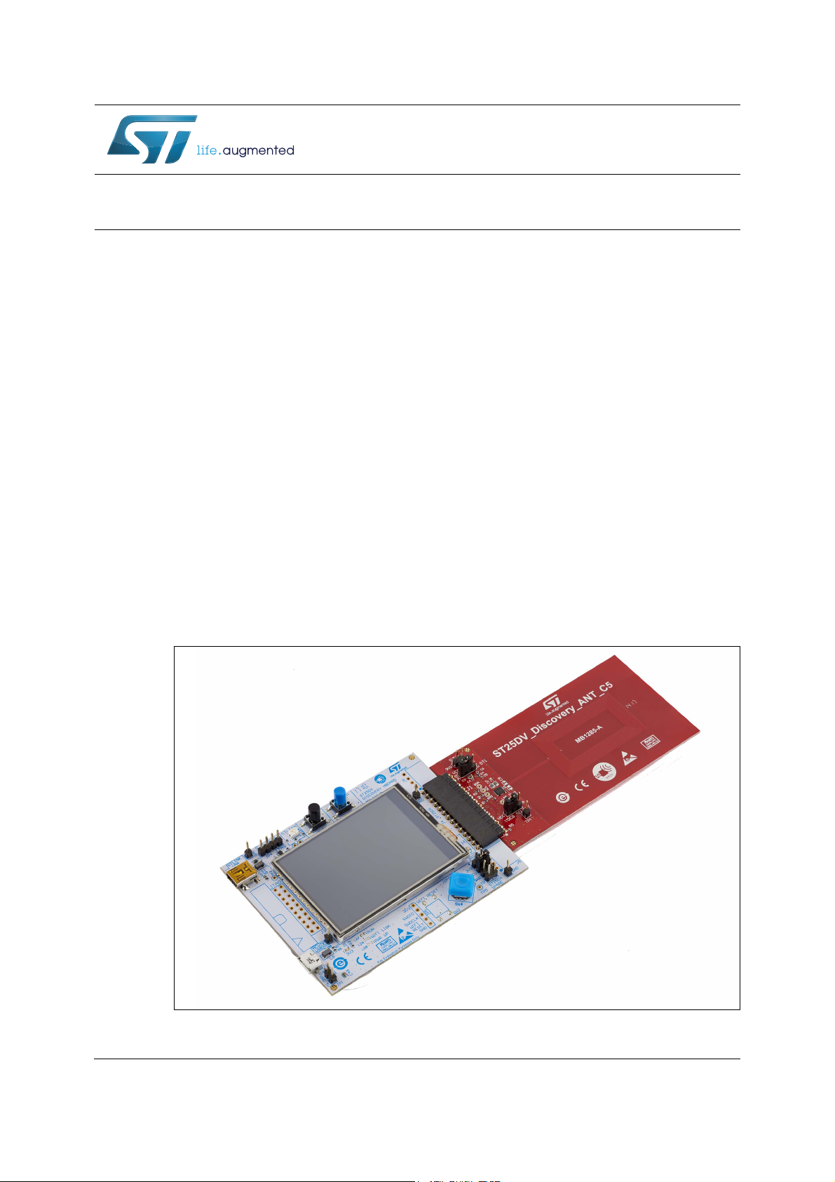
The ST25DV-DISCOVERY is a demonstration kit that evaluates features and capabilities of
the ST25DV04K Dynamic NFC / RFID Tag.
The kit is composed of two boards:
• MB1283 (ST25DX_Discovery_Mboard): a microprocessor mother board, which includes
a complement of hardware and software tools allowing the use the full STM32 Nucleo
ecosystem. The board is powered through one USB connector.
• MB1285 (ST25DV_Discovery_ANT_C5): a daughter board, which embeds the
ST25DV04K Dynamic NFC / RFID tag device. This daughter board provides a buffering
data transfer capability and has a Class 5 antenna.
The communication link between boards is the I2C serial and the power is provided by the
processor card or via energy harvesting. Specific data lines complete the pin connector
assignment shared between cards.
A variety of demonstrations can be performed with this kit. The kit allows the users to
develop and to test their own applications.
The MB1283 and the MB1285 boards schematics, BOM, gerber files, drivers and firmware
are available at the STMicroelectronics website at www.st.com.
Figure 1. ST25DV-DISCOVERY mother board and daughter board
September 2017 DocID029579 Rev 2 1/22
www.st.com
1
Page 2

Contents UM2096
Contents
1 Description . . . . . . . . . . . . . . . . . . . . . . . . . . . . . . . . . . . . . . . . . . . . . . . . . 4
2 Features . . . . . . . . . . . . . . . . . . . . . . . . . . . . . . . . . . . . . . . . . . . . . . . . . . . 5
2.1 MB1283 board features . . . . . . . . . . . . . . . . . . . . . . . . . . . . . . . . . . . . . . . 5
2.2 MB1285 board features . . . . . . . . . . . . . . . . . . . . . . . . . . . . . . . . . . . . . . . 5
3 Hardware layout . . . . . . . . . . . . . . . . . . . . . . . . . . . . . . . . . . . . . . . . . . . . 6
3.1 MB1283 board layout . . . . . . . . . . . . . . . . . . . . . . . . . . . . . . . . . . . . . . . . . 6
3.2 MB1285 board layout . . . . . . . . . . . . . . . . . . . . . . . . . . . . . . . . . . . . . . . . . 7
4 ST25DV-DISCOVERY kit powering and startup . . . . . . . . . . . . . . . . . . . 8
5 Program and debug the ST25DV-DISCOVERY kit . . . . . . . . . . . . . . . . . 9
6 Hardware implementation . . . . . . . . . . . . . . . . . . . . . . . . . . . . . . . . . . . 10
6.1 MB1283 board schematics . . . . . . . . . . . . . . . . . . . . . . . . . . . . . . . . . . . . 10
6.2 MB1285 board schematics . . . . . . . . . . . . . . . . . . . . . . . . . . . . . . . . . . . . 20
7 Revision history . . . . . . . . . . . . . . . . . . . . . . . . . . . . . . . . . . . . . . . . . . . 21
2/22 DocID029579 Rev 2
Page 3

UM2096 List of figures
List of figures
Figure 1. ST25DV-DISCOVERY mother board and daughter board . . . . . . . . . . . . . . . . . . . . . . . . . . 1
Figure 2. ST25DV-DISCOVERY overview. . . . . . . . . . . . . . . . . . . . . . . . . . . . . . . . . . . . . . . . . . . . . . 4
Figure 3. MB1283 board top view . . . . . . . . . . . . . . . . . . . . . . . . . . . . . . . . . . . . . . . . . . . . . . . . . . . . 6
Figure 4. MB1283 board bottom view . . . . . . . . . . . . . . . . . . . . . . . . . . . . . . . . . . . . . . . . . . . . . . . . . 6
Figure 5. MB1285 board top view . . . . . . . . . . . . . . . . . . . . . . . . . . . . . . . . . . . . . . . . . . . . . . . . . . . . 7
Figure 6. MB1285 board bottom view . . . . . . . . . . . . . . . . . . . . . . . . . . . . . . . . . . . . . . . . . . . . . . . . . 7
Figure 7. MB1283 schematics - top level . . . . . . . . . . . . . . . . . . . . . . . . . . . . . . . . . . . . . . . . . . . . . . 11
Figure 8. MB1283 schematics - power supply . . . . . . . . . . . . . . . . . . . . . . . . . . . . . . . . . . . . . . . . . . 12
Figure 9. MB1283 schematics - STM32F405 . . . . . . . . . . . . . . . . . . . . . . . . . . . . . . . . . . . . . . . . . . 13
Figure 10. MB1283 schematics - EH . . . . . . . . . . . . . . . . . . . . . . . . . . . . . . . . . . . . . . . . . . . . . . . . . . 14
Figure 11. MB1283 schematics - ST-LINK JTAG . . . . . . . . . . . . . . . . . . . . . . . . . . . . . . . . . . . . . . . . 15
Figure 12. MB1283 schematics - LCD . . . . . . . . . . . . . . . . . . . . . . . . . . . . . . . . . . . . . . . . . . . . . . . . . 16
Figure 13. MB1283 schematics - WiFi
Figure 14. MB1283 schematics - ST25DX connectors . . . . . . . . . . . . . . . . . . . . . . . . . . . . . . . . . . . . 18
Figure 15. MB1283 schematics - USB . . . . . . . . . . . . . . . . . . . . . . . . . . . . . . . . . . . . . . . . . . . . . . . . . 19
Figure 16. MB1285 board schematics . . . . . . . . . . . . . . . . . . . . . . . . . . . . . . . . . . . . . . . . . . . . . . . . . 20
®
BLE . . . . . . . . . . . . . . . . . . . . . . . . . . . . . . . . . . . . . . . . . . . . 17
DocID029579 Rev 2 3/22
3
Page 4

Description UM2096
1 Description
The ST25DV series Dynamic NFC tags discovery kit (ST25DV-DISCOVERY) allows the
user to evaluate the features and capabilities of the ST25DV04K products.
The ST25DV-DISCOVERY kits comes with application notes, software applications, drivers,
BOM (bill of materials), board schematics, gerber files and firmware schematics. All these
documents help the user to reduce the design efforts and they can be downloaded at
www.st.com.
The MB1283 in standard edition is designed to help the user explore the features of the
ST25DV04K products with the support of the STM32 Nucleo ecosystem. This mother board
uses a 32-bit ARM
develop the applications.
The MB1283 standard edition board is powered through the USB bus. It is based on an
STM32F405 line microcontroller and includes:
• An ST-LINK embedded debug tool interface
• A 2.4” TFT LCD with touch screen capability
• LEDs
• Push buttons (reset and user)
• A mini USB debug connector
• A user-dedicated micro USB connector.
®
Cortex™-M4 CPU with FPU high-performance microcontroller to
The MB1283 demonstration edition board includes all of the features of the standard edition
plus a HE20 JTAG connector, a WiFi
additional features demonstrate various use cases.
The MB1285 is a dynamic NFC/RFID tag providing a buffering data transfer capability
expansion board usable with the MB1283 mother board. This daughter board interfaces with
the STM32 MCU via the I2C.
Figure 2. ST25DV-DISCOVERY overview
®
module and a low-energy Bluetooth
®
module. These
4/22 DocID029579 Rev 2
Page 5

UM2096 Features
2 Features
2.1 MB1283 board features
The MB1283 (ST25DX_Discovery_Mboard) is a ready-to-use printed circuit board (PBC)
which includes:
• On standard edition:
– An STM32F405VGT6 LQFP100 32-bit microcontroller with 1 Mbyte of Flash
memory and 192 + 4 Kbyte of SRAM.
– LCD color screen (320 x 200 pixels)
– Touch screen driver
– Different color LEDs (power, user, WiFi
– User push button
– Reset button
– Joystick for menu selection
– On board ST link for microcontroller firmware upgrade and debug
– ST-LINK mini USB
– User micro USB
– USB micro or mini connector for board powering
– Demonstration use cases flashed in memory
• On demonstration edition:
– All features available on the standard edition
– A JTAG connector
– Bluetooth
–WiFi
®
low-energy module
®
module
®
status)
2.2 MB1285 board features
The MB1285 (ST25DV_Discovery_ANT_C5) is a ready-to-use PCB which includes:
• A ST25DV04K Dynamic NFC/RFID tag IC with 4 Kbits EEPROM which provides a
buffering data-transfer capability
• Class 5 single-layer inductive antenna etched on the PCB (ANT C5)
DocID029579 Rev 2 5/22
21
Page 6
Hardware layout UM2096
8VHU
EXWWRQ
5HVHW
EXWWRQ
67/,1.DFWLYLW\
/('
([WHQVLRQ
FRQQHFWRUV
:L)L
UHVHWEXWWRQ
:L),
6:XSGDWH
:L)L
VWDWXV/('
([WHQVLRQFRQQHFWRU
*3,2VHWWLQJ
6:EXV
67/,1.
(QHUJ\KDUYHVWLQJ
/('
8VHU/('
/&'
WRXFKVFUHHQ
-R\VWLFN
3RZHU9/('
8VHU86%
67/,1.86%
670)
5RRPIRU%/(0RGXOH
67067/,1.
5RRPIRU:L)L
PRGXOH
7HVWVSRLQWVDYDLODEOHIRU
H[WHUQDOFRQQHFWLRQV
5HJXODWRU
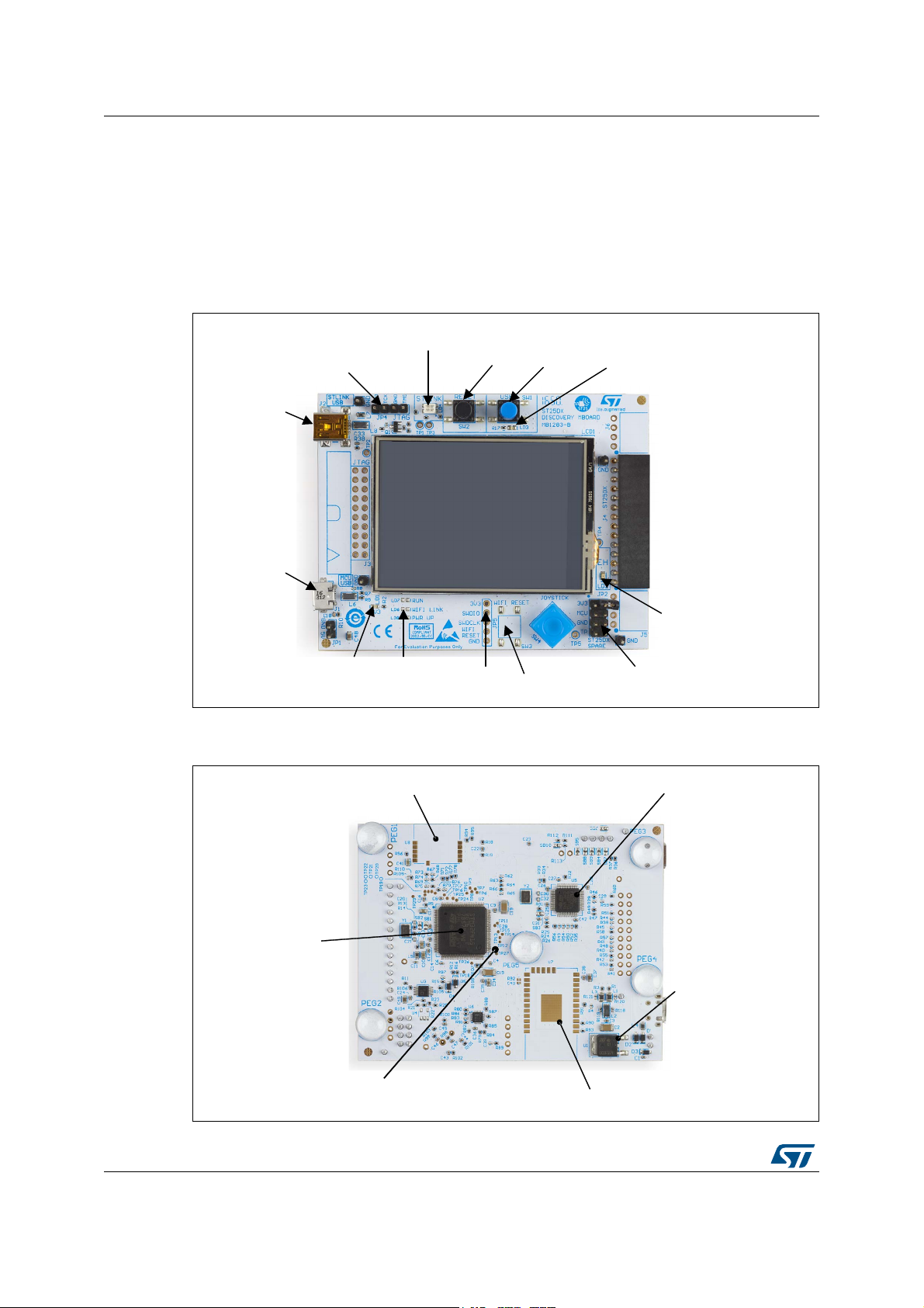
3 Hardware layout
3.1 MB1283 board layout
This section presents the layout of the MB1283 board from a top view (see Figure 3) and a
bottom view (see Figure 4).
Figure 3. MB1283 board top view
1. * Available only on demonstration edition.
Figure 4. MB1283 board bottom view
6/22 DocID029579 Rev 2
Page 7

UM2096 Hardware layout
9(+RU9&&SRZHUVHOHFWLRQ
9(+9&&FRQQHFWLRQ
$QWHQQD
9'*VHWWLQJ 67'9
069
3.2 MB1285 board layout
This section presents the layout of the MB1285 board from a top view (see Figure 5) and a
bottom view (see Figure 6).
Figure 5. MB1285 board top view
Figure 6. MB1285 board bottom view
DocID029579 Rev 2 7/22
21
Page 8

ST25DV-DISCOVERY kit powering and startup UM2096
4 ST25DV-DISCOVERY kit powering and startup
The mother board and the daughter board must be connected together.
The ST25DV-DISCOVERY kit is powered by an USB bus via a cable connected to the
power source (like a PC).
When powered up, the microcontroller starts the firmware, which is already downloaded in
the Flash memory. This is a demonstration of the different capabilities of the ST25DV04K
(like RF on/off, change vCard message for example). There are no modifications nor
configuration to be done on the board to run the demo. Refer to the firmware’s user manual
available on STMicroelectronics website to get more details.
8/22 DocID029579 Rev 2
Page 9

UM2096 Program and debug the ST25DV-DISCOVERY kit
5 Program and debug the ST25DV-DISCOVERY kit
In order to Flash or debug an STM32 microcontroller application on the ST25DVDISCOVERY kit, simply connect the mini USB cable.
The on-board ST-LINK in-circuit debugger and programmer allows to start the dedicated
tools.
Then, launch the ST-LINK utility PC software (available for download at STMicroelectronics
website).
For more information or documentation on the ST-LINK in-circuit debugger and
programmer, visit www.st.com.
DocID029579 Rev 2 9/22
21
Page 10

Hardware implementation UM2096
6 Hardware implementation
The pages hereafter show the ST25DV-DISCOVERY schematics for:
• ST25DX_Discovery_MBoard (board reference MB1283)
• ST25DV_Discovery_ANT_C5 (board reference MB1285).
6.1 MB1283 board schematics
This section presents the schematics for the MB1283 board.
10/22 DocID029579 Rev 2
Page 11
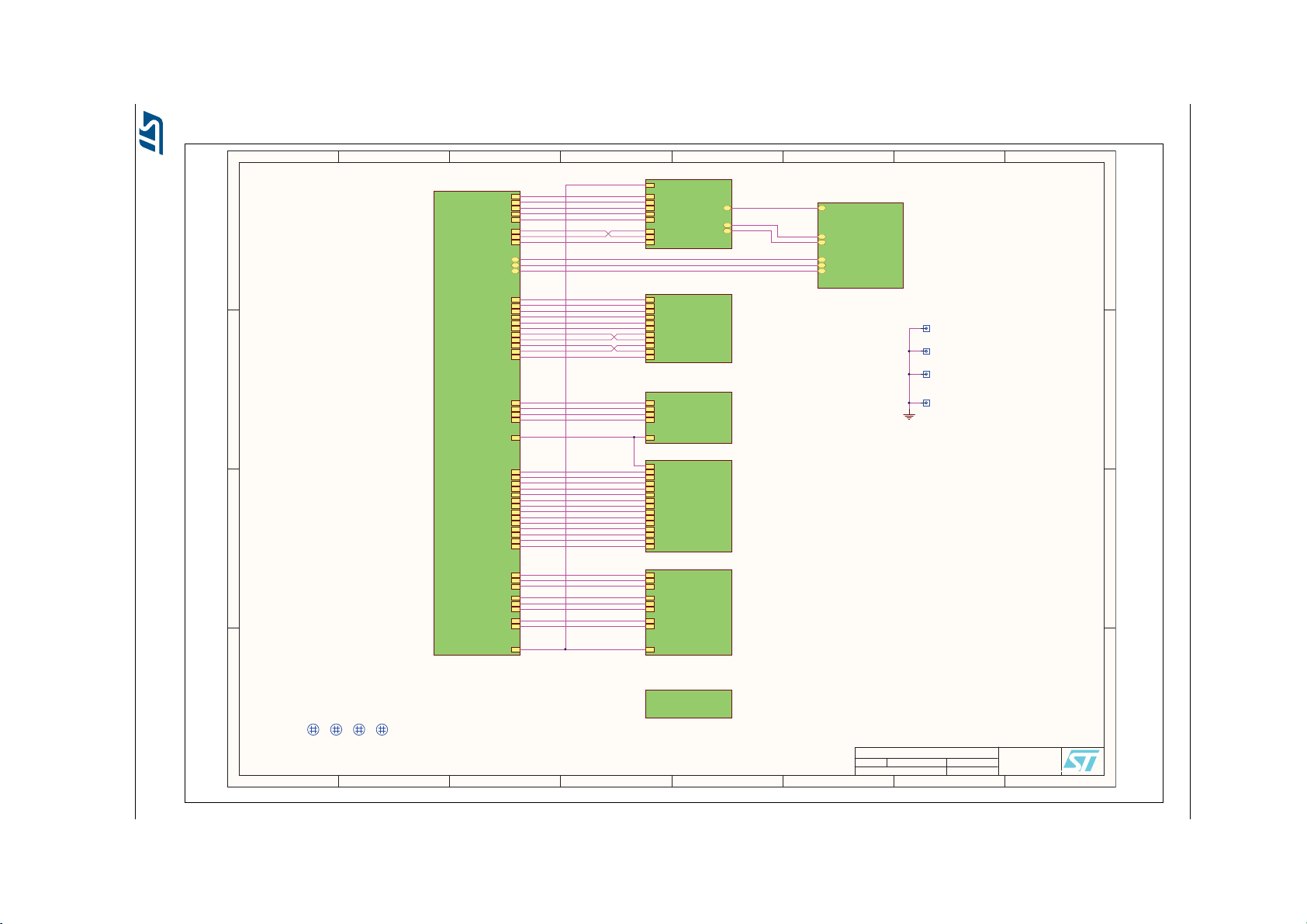
Figure 7. MB1283 schematics - top level
1
1
2
2
3
3
4
4
5
5
6
6
7
7
8
8
D D
C C
B B
A A
19
ST25Dx DISCOVERY MBOARD
B
07/11/2016
Title:
Size: Reference:
Date: Sheet: of
A3
£
Revision:
MB1283
STMicroelectronics
635, Route des Lucioles
06560 VALBONNE
FRANCE
TopLevel.SchDoc
TSCR_I2C_SCL
TSCR_I2C_SDA
TSCR_IRQ
TE
SDA
WR
RS
CSX
NRST
U_LCD
LCD.SchDoc
U_Pwr Supply
Pwr Supply.SchDoc
SPARE
EH
GPO_1
I2C_SCL
I2C_SDA
SPI_MOSI
SPI_MISO
SPI_CLK
SPI_CSn
IRQ
UART_RX
UART_TX
UART_RTSn
UART_CTSn
MCU_CLK
U_ST25DX Connectors
ST25DX Connectors.SchDoc
TDO/SWO
TMS/SWDIO
RESET#
TRST
TDI
TCK_SWCLK
UART_TX
UART_RX
STLK_MCO
STL_USB_D_P
STL_USB_D_N
USB_RENUMn
U_STLink-Jtag
STLink-Jtag.SchDoc
TMS/SWDIO
TDI
TCK_SWCLK
TDO/SWO
TRST
BLE_SPI_IRQ
BLE_SPI_CSN
BLE_SPI_MOSI
BLE_SPI_MISO
BLE_SPI_CLK
BLE_RESET
WF_UART_TX
WF_UART_RX
WF_UART_RTS
WF_UART_CTS
WF_RESET
STLK_UART_TX
STLK_UART_RX
TSCR_I2C_SCL
TSCR_I2C_SDA
TSCR_IRQ
STLK_MCO
ST25DX_MCU_CLK
ST25DX_SPARE
ST25DX_EH
ST25DX_GPO_1
ST25DX_I2C_SCL
ST25DX_I2C_SDA
ST25DX_SPI_MOSI
ST25DX_SPI_MISO
ST25DX_SPI_CLK
ST25DX_SPI_CSn
ST25DX_IRQ
ST25DX_UART_RX
ST25DX_UART_TX
ST25DX_UART_RTSn
ST25DX_UART_CTSn
TSCR_SPI_MOSI
TSCR_SPI_CSn
TSCR_SPI_CLK
RESET#
POT_I2C_SDA
POT_I2C_SCL
POT_IN
I_MEAS_OUT
TSCR_TE
TSCR_WR
MCU_USB_D_N
MCU_USB_ID
MCU_USB_D_P
U_STM32F415
STM32F415.SchDoc
SPI_IRQ
SPI_CSN
SPI_MOSI
SPI_MISO
SPI_CLK
BLE_RESET
UART_TX
UART_RX
UART_RTS
UART_CTS
WF_RESET
U_WIFI-BLE
WIFI-BLE.SchDoc
EH
POT_I2C_SDA
POT_I2C_SCL
POT_IN
I_MEAS_OUT
U_EH
EH.SchDoc
MIR1
Mire
MIR2
Mire
MIR3
Mire
MIR4
Mire
1
JP6
HE14
1
JP7
HE14
1
JP8
HE14
1
JP9
HE14
GND
GROUND PINS
STL_USB_D_N
MCU_USB_D_N
MCU_USB_D_P
STL_USB_D_P
MCU_USB_ID
USB_RENUMn
U_USB
USB.SchDoc
UM2096 Hardware implementation
DocID029579 Rev 2 11/22
Page 12

12/22 DocID029579 Rev 2
1
1
2
2
3
3
4
4
5
5
6
6
7
7
8
8
D D
C C
B B
A A
29
ST25Dx DISCOVERY MBOARD
B
07/11/2016
Title:
Size: Reference:
Date: Sheet: of
A3
£
Revision:
MB1283
STMicroelectronics
635, Route des Lucioles
06560 VALBONNE
FRANCE
Pwr Supply.SchDoc
VUSB_MCU
VUSB_ST_LINK
D1
BAT60JFILM
D3
BAT60JFILM
D2
BAT60JFILM
1 2
JP1
HE14
5V
Vin
IN
GND
GND
Vout
OUT
U1 KF33BDT
C1
100nF
C2
2.2uF/16V
C3
100nF
1 2
4 3
L2
744232090
1 2
L1
742792042
1 2
L3
742792042
5V
GND_USB
R1
0R
R3
0R
R4
NC
GND
VCC
LD1
GREEN
R2
510R
GND_USB
C48
10uF/25V
3V3
PEG1
SJ5306
PEG2
SJ5306
PEG3
SJ5306
PEG4
SJ5306
R118
0R NC
R119
0R NC
R120
0R NC
R121
0R NC
PEG5
SJ5306
Figure 8. MB1283 schematics - power supply
Hardware implementation UM2096
Page 13

Figure 9. MB1283 schematics - STM32F405
1
1
2
2
3
3
4
4
5
5
6
6
7
7
8
8
D D
C C
B B
A A
39
ST25Dx DISCOVERY MBOARD
B
07/11/2016
Title:
Size: Reference:
Date: Sheet: of
A3
£
Revision:
MB1283
STMicroelectronics
635, Route des Lucioles
06560 VALBONNE
FRANCE
VSSA
20
VREF+
21
VSS74VSS
10
VDD
19
PB0/ADC12_IN8
35
VDD11VDD
28
VSS
27
PH0/OSC_IN
12
PH1/OSC_OUT
13
BOOT0
94
NRST
14
VCAP_1
49
VBAT
6
PA0/USART2_CTS
23
PA1/USART2_RTS
24
PA2/USART2_TX
25
PA3/USART2_RX
26
PA4/SPI1_NSS
29
PA5/SPI1_SCK
30
PA6/SPI1_MISO
31
PA7/SPI1_MOSI
32
PA8/I2C3_SCL
67
PA9
68
PA10/OTG_FS_ID
69
PA11/OTG_FS_DM
70
PA12/OTG_FS_DP
71
PA13/JTMS-SWDIO
72
PA14/JTCK/SWCLK
76
PA15/JTDI
77
PB1/ADC12_IN9
36
PB2
37
PB3/JTDO
89
PB4/NJTRST
90
PB5/I2C1_SMBA
91
PB6/I2C1_SCL
92
PB7/I2C1_SDA
93
PB8
95
PB9
96
PB10/I2C2_SCL
47
PB11/I2C2_SDA
48
PB12/SPI2_NSS
51
PB13/SPI2_SCK
52
PB14/USART3_RTS
53
PB15
54
PC0
15
PC1
16
PC2/SPI2_MISO
17
PC3/SPI2_MOSI
18
PC4/ADC12_IN14
33
PC5/ADC12_IN15
34
PC6/USART6_TX
63
PC7/USART6_RX
64
PC8
65
PC9/I2C3_SDA
66
PC10/SPI3_SCK
78
PC11/SPI3_MISO
79
PC12/SPI3_MOSI
80
PC13
7
PC14
8
PC15
9
PD0
81
PD1
82
PD2
83
PD3
84
PD4
85
PD5
86
PD6
87
PD7
88
PD8/USART3_TX
55
PD9/USART3_RX
56
PD10/USART3_CK
57
PD11/USART3_CTS
58
PD12
59
PD13
60
PD14
61
PD15
62
PE0
97
PE1
98
PE2
1
PE3
2
PE4
3
PE5
4
PE6
5
PE7
38
PE8
39
PE9
40
PE10
41
PE11
42
PE12
43
PE13
44
PE14
45
PE15
46
VDD50VDD75VDD
100
VCAP_2
73
VDDA
22
VSS
99
U2
STM32F415VGT6
STM32F415.SchDoc
TMS/SWDIO
TDI
TCK_SWCLK
TDO/SWO
TRST
BLE_SPI_IRQ
BLE_SPI_CSN
BLE_SPI_MOSI
BLE_SPI_MISO
BLE_SPI_CLK
BLE_RESET
WF_UART_TX
WF_UART_RX
WF_UART_RTS
WF_UART_CTS
WF_RESET
STLK_UART_TX
STLK_UART_RX
TSCR_I2C_SCL
TSCR_I2C_SDA
TSCR_IRQ
1 2
Y1
NX3225GD-8MHZ
C20
10pF
C21
10pF
GND
SB1
SB2
STLK_MCO
ST25DX_MCU_CLK
ST25DX_SPARE
ST25DX_EH
ST25DX_GPO_1
ST25DX_I2C_SCL
ST25DX_SPI_MOSI
ST25DX_SPI_MISO
ST25DX_SPI_CLK
ST25DX_SPI_CSn
ST25DX_IRQ
ST25DX_UART_RX
ST25DX_UART_TX
ST25DX_UART_RTSn
ST25DX_UART_CTSn
C7
100nF
C9
100nF
GND
VCC
GND
TSCR_SPI_MOSI
TSCR_SPI_CSn
TSCR_SPI_CLK
C5
100nF
C6
100nF
C8
100nF
GND
C4
100nF
SW2
TD-0341X-BLACK
C23
100nF
GND
RESET#
VCC
GND
C10
1uF/25V
C17
1uF/25V
C15
2.2uF/16V
C19
2.2uF/16V
C12
100nF
C16
100nF
GND
1 2
L5
FCM1608KF-601T03
VCC
C11
100nF
GND
GND
R6
47R
C13
1uF/25V
C14
100nF
GND
R9
0R
VCC
GND
GND
R13
0R
R14
0R
JOYSTICK
SW1
TD-0341X-BLUE
R19
100R
R18
4K7
C22
100nF
VCC
GND
LD3
ORANGE
R17
680R
GND
POT_I2C_SCL
POT_I2C_SDA
D4
BAT60JFILM
D5
BAT60JFILM
R150RR16
1K5
GND
VCC
POT_IN
I_MEAS_OUT
LD2
YELLOW
R12
0R
GND
1 2
3 4
576
8
JP2
HE14
VCC
GND
TSCR_TE
TSCR_WR
R11
360R
R97
NC
TP4
PTH/1.0mm
TP5
PTH/1.0mm
LEFT1LEF
RIGHT
4
UP
6
DOWN
3
SEL
2
COM
5
SW4
MT-008 A
R98
10K
R99
10K
R100
10K
R101
10K
R102
10K
C43
100nF
C44
100nF
C45
100nF
C46
100nF
C47
100nF
R103
10R
GND GND
VCC
JOY_SEL
JOY_LEFT
JOY_RIGHT
JOY_UP
JOY_DOWN
JOY_SEL
JOY_LEFT
JOY_RIGHT
JOY_UP
JOY_DOWN
TP6 SMD/0.8mm
TP7 SMD/0.8mm
TP8 SMD/0.8mm
TP9 SMD/0.8mm
TP10SMD/0.8mm
TP12SMD/0.8mm
TP13SMD/0.8mm
TP14SMD/0.8mm
TP15SMD/0.8mm
TP16SMD/0.8mm
TP17SMD/0.8mm
TP19SMD/0.8mm
TP20SMD/0.8mm
TP21SMD/0.8mm
TP22SMD/0.8mm
TP23SMD/0.8mm
TP26SMD/0.8mm
TP11SMD/0.8mm
TP18SMD/0.8mm
TP24SMD/0.8mm
TP25SMD/0.8mm
TP27SMD/0.8mm
TP28SMD/0.8mm
TP29
SMD/0.8mm
MCU_USB_ID
MCU_USB_D_N
MCU_USB_D_P
R107
1K5
ST25DX_I2C_SDA
R108
1K5
VCC
R109
NC
R110
510R
UM2096 Hardware implementation
DocID029579 Rev 2 13/22
Page 14

14/22 DocID029579 Rev 2
1
1
2
2
3
3
4
4
5
5
6
6
7
7
8
8
D D
C C
B B
A A
49
B
07/11/2016
Size: Reference:
Date: Sheet: of
A3
£
Revision:
MB1283
635, Route des Lucioles
06560 VALBONNE
FRANCE
EH
RS+
5
GND
1
OUT
3
GND
2
RS-
4
U4
MAX9938FEUK-T NC
R22
4R3
GND
GND
VCC
C24
100nF
GND
POT_I2C_SDA
POT_I2C_SCL
POT_IN
I_MEAS_OUT
R23
0R
R21
0R
R20
0R
ST25Dx DISCOVERY MBOARD
Title:
EH.SchDoc
A
1
GND
7
CS/ADO
3
SDO/NC
4
W
10
VDD
9
B
2
DIS
8
SDI/SDA
5
CLK/SCL
6
U3
AD5161BRMZ100
VCC
GND GND
R104
0R
R105
1K5
R106
1K5
C49
10uF/25V
GND
Figure 10. MB1283 schematics - EH
Hardware implementation UM2096
Page 15
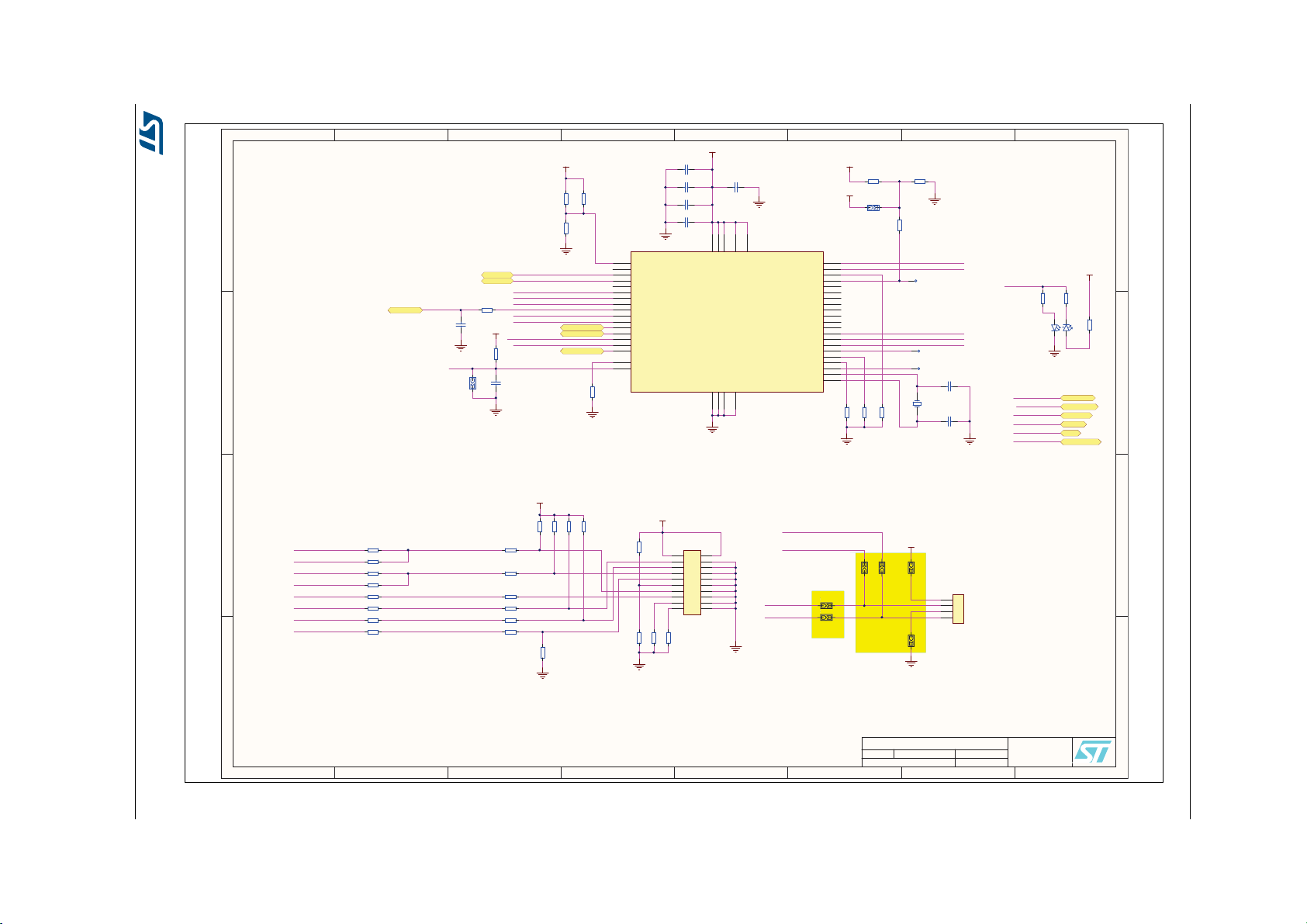
Figure 11. MB1283 schematics - ST-LINK JTAG
1
1
2
2
3
3
4
4
5
5
6
6
7
7
8
8
D D
C C
B B
A A
59
ST25Dx DISCOVERY MBOARD
B
07/11/2016
Title:
Size: Reference:
Date: Sheet: of
A3
£
Revision:
MB1283
STMicroelectronics
635, Route des Lucioles
06560 VALBONNE
FRANCE
VSSA
8
PA0/WKUP
10
PA1
11
PA3/USART2_RX
13
PA4
14
PA5/SPI1_SCK
15
PA6/SPI1_MISO
16
PA7/SPI1_MOSI
17
PA8/MCO
29
PA9
30
PA10
31
PA11 /U SB DM
32
PA13/JTMS/SWDIO
34
PA14/JTCK/SWCLK
37
PA15
38
PA12/USBDP
33
VSS47VSS
23
VDD
24
PA2/USART2_TX
12
PB0
18
PB1
19
PB2/BOOT1
20
PB3/JTDO
39
PB4
40
PB5
41
PB6
42
PB7
43
PB8
45
PB9
46
PB10
21
PB12
25
PB13/SPI2_SCK
26
PB14/SPI2_MISO
27
PB15/SPI2_MOSI
28
VDD36VDD
48
VSS
35
PC14/OSC32_IN
3
PC15/OSC32_OUT
4
PD0/OSCIN
5
PD1/OSCOUT
6
PC13/TAMPER-RTC
2
BOOT0
44
NRST
7
VBAT
1
PB11
22
VDDA
9
U5
STM32F103CBT6
STLink-Jtag.SchDoc
C25
100nF
VCC
C26
100nF
C27
100nF
C28
100nF
GND
GND
R34
10K
R33
NC
GND
1 2
Y2
NX3225GD-8MHZ
C30
10pF
C32
10pF
GND
STM_RST
R31
100K
C31
100nF
SB3
GND
VCC
R24
4K7
R25
NC
R26
4K7
VCC
GND
T_JTCK
T_JTDO
T_JTDI
T_NRST
T_JRST
R35
100K
STM_JTMS_SWDIO
T_JTCK
T_JTMS
T_SWDIO_IN
LED_STLINK
T_SWO
R29
100R NC
C29
20pF NC
GND
STM_JTCK
R32
100K
GND
R28
100R
R30
100R
VCC
LED_STLINK
R46 0R
R43 NC
R47 0R
R49
100R
R50 NC
R52 NC
R54 NC
R56
0R
T_JTCK
T_JTDO
T_JTDI
T_SWO
T_NRST
T_JRST
T_SWDIO_IN
T_JTMS
TDO/SWO
TMS/SWDIO
RESET#
TRST
TDI
TCK_SWCLK
TDO/SWO
TMS/SWDIO
RESET#
TRST
TDI
TCK_SWCLK
TDO/SWO
TMS/SWDIO
RESET#
TRST
TDI
TCK_SWCLK
1
3
5
7
9
11
13
15
17
19
2
4
6
8
10
12
14
16
18
20
J3
HE10 20PTS R.ANGLE NC
R44
NC
R48
NC
R51
22R
R53
22R
R55
22R
R57
NC
R39NCR40NCR41NCR42
NC
R61
NC
VCC
GND
VCC
GND
R45
NC
R58
10K
R59
10K
R60
10K
GND
1
2
3
4
JP4
HE14
SB6
VCC
TMS/SWDIO
TCK_SWCLK
SB7
SB9
GND
SB8
SB5SB4
STM_JTCK
STM_JTMS_SWDIO
B9
S
B
S
B
S
B8
RESERVED
DEFAULT
GND
UART_TX
UART_RX
STLK_MCO
TP1
PTH/1.0mm
TP2 PTH/1.0mm
TP3 PTH/1.0mm
C42
100nF
GND
STL_USB_D_N
STL_USB_D_P
RED
YEL
LD4
HSMF-A201-A00J1
R27
0R
R111
2K7
R112
4K7
R113
0R
SB10
VCC
5V
GND
PWR_EXT
USB_RENUMn
UM2096 Hardware implementation
DocID029579 Rev 2 15/22
7
SB5
4
SB6
S
Page 16

16/22 DocID029579 Rev 2
1
1
2
2
3
3
4
4
5
5
6
6
7
7
8
8
D D
C C
B B
A A
69
ST25Dx DISCOVERY MBOARD
B
07/11/2016
Title:
Size: Reference:
Date: Sheet: of
A3
£
Revision:
MB1283
STMicroelectronics
635, Route des Lucioles
06560 VALBONNE
FRANCE
LCD.SchDoc
D0
29
D1
28
D2
27
D3
26
D4
25
D5
24
D6
23
D7
22
D8
21
D9
20
D10
19
D11
18
D12
17
D13
16
D14
15
D15
14
D16
13
D17
12
YU
1
XL
2
YD
3
XR
4
GND
5
VCI
6
IOVCC
7
NC8NC9NC
10
TE
11
SDA
30
DOTCLK
31
EN
32
HSYNC
33
VSYNC
34
RD
35
WR
36
RS
37
/CS
38
/RESET
39
IM0
40
IM1
41
IM2
42
IM3
43
A-BKLGHT
44
K1-BKLGHT
45
K2-BKLGHT
46
K3-BKLGHT
47
K4-BKLGHT
48
LCD1
FRD24048TP
R73
4K7
R74NCR75NCR76
4K7
R68
4K7
R67
NC
R70NCR69
4K7
R72 0R
R71 0R
R78 0R
R77 0R
GND
GND
VCC
VCC
GND
VCC
C34
4.7uF/25V
C35
100nF
GND
IN0/GPIO0
8
GND
10
X+/GPIO4
13
SDAT
5
SCLK
4
VCC
6
GND(THPAD)
17
IN1/GPIO1/MODE
9
IN2/GPIO2
11
IN3/GPIO3
12
INT
2
A0/DATA_OUT
3
DATA _I N
7
VIO
14
Y+/GPIO5
15
X-/GPIO6
16
Y-/ GP I O7
1
U6
STMPE811QTR
C36
100nF
VCC
GND
YU
XL
YD
XR
YU
XL
YD
XR
R88
100K
R87
100K
R85
100K
R84
100K
GND
GND
R81
4K7
R82
4K7
VCC
R80
4K7
VCC
R79
4K7
R83
NC
R86
0R
GND
R63
4K7
R62
NC
R65NCR64
4K7
VCC
GND
R66
4K7
TSCR_I2C_SCL
TSCR_I2C_SDA
TSCR_IRQ
GND
TE
SDA
WR
RS
CSX
NRST
SPI MODE
Figure 12. MB1283 schematics - LCD
Hardware implementation UM2096
Page 17

Figure 13. MB1283 schematics - WiFi® BLE
1
1
2
2
3
3
4
4
5
5
6
6
7
7
8
8
D D
C C
B B
A A
79
ST25Dx DISCOVERY MBOARD
B
07/11/2016
Title:
Size: Reference:
Date: Sheet: of
A3
£
Revision:
MB1283
STMicroelectronics
635, Route des Lucioles
06560 VALBONNE
FRANCE
WIFI-BLE.SchDoc
GPIO
2
GND
6
SPI_MISO
8
SPI_CS
10
SPI_IRQ
4
ANA_TEST
3
VIN
5
EXT_LPCLK
1
SPI_MOSI
9
SPI_CLK
7
BT_RESET
11
U8
SPBTLE-RF NC
TXD1
6
GND
23
RTS1_DP
10
VCC
24
RXD1
8
CTS1_DN
9
GPIO0
16
GPIO1/PWM
17
GPIO2
19
GPIO3
1
GPIO4
18
GPIO5
20
GPIO6/WKUP/SLEEP_INH
22
GPIO7/STA/AP_SW
13
GPIO8/ADC
4
GPIO9
7
GPIO10/LED_RUN
5
GPIO11
11
GPIO12
12
GPIO13/LED_WIFI_LINK_UP
15
GPIO14/LED_PWR_UP
14
GPIO15/DAC
21
GND_PAD
25
RESETn
3
BOOT0
2
TMS
26
TDI
27
TRST
28
TCK
29
TDO
30
U7
SPWF01SA.11 NC
R96
47K
C41
1uF/25V
R95
10K
R94
10K
SPI_IRQ
SPI_CSN
SPI_MOSI
SPI_MISO
SPI_CLK
BLE_RESET
VCC VCC
VCC
GND
GND
VCC
C38
100nF
C37
10uF/25V
GND
GND
C39
100nF/NC
SW3
TD-0341X-BLACK-NC
R89
4K7
GND
GND
R91
680R
LD7
GREEN-NC
R93
680R
LD8
GREEN-NC
R90
680R
LD6
GREEN-NC
GND
WIFI LINK
RUN
PWR UP
R92
4K7/NC
C40
100nF/NC
VCC
GND
1
2
3
4
5
JP5
HE14/NC
VCC
GND
SPW_SWDIO
SPW_SWCLK
WF_RESET
WF_RESET
WF_RESET
SPW_SWDIO
SPW_SWCLK
UART_TX
UART_RX
UART_RTS
UART_CTS
UM2096 Hardware implementation
DocID029579 Rev 2 17/22
Page 18

18/22 DocID029579 Rev 2
1
1
2
2
3
3
4
4
5
5
6
6
7
7
8
8
D D
C C
B B
A A
89
ST25Dx DISCOVERY MBOARD
B
07/11/2016
Title:
Size: Reference:
Date: Sheet: of
A3
£
Revision:
MB1283
STMicroelectronics
635, Route des Lucioles
06560 VALBONNE
FRANCE
ST25DX Connectors.SchDoc
1
2
3
4
5
6
7
8
9
10
11
12
13
14
J4
SSW-114-02-G-S-RA
1
2
3
4
J5
SSW-104-02-G-S-RA NC
SPARE
EH
GPO_1
I2C_SCL
I2C_SDA
SPI_MOSI
SPI_MISO
SPI_CLK
SPI_CSn
GND
VCC
1
2
3
4
J6
SSW-104-02-G-S-RA NC
IRQ
UART_RX
UART_TX
UART_RTSn
UART_CTSn
MCU_CLK
VCC
GND
Figure 14. MB1283 schematics - ST25DX connectors
Hardware implementation UM2096
Page 19

Figure 15. MB1283 schematics - USB
1
1
2
2
3
3
4
4
5
5
6
6
7
7
8
8
D D
C C
B B
A A
99
ST25Dx DISCOVERY MBOARD
B
07/11/2016
Title:
Size: Reference:
Date: Sheet: of
A3
£
Revision:
MB1283
STMicroelectronics
635, Route des Lucioles
06560 VALBONNE
FRANCE
USB.SchDoc
VBUS
1
D-
2
D+
3
GND
5
SHLD
G1
ID
4
SHLD
G2
SHLD
G3
SHLD
G4
J2
5075BMR-05-SM
VUSB_ST_LINK
R36 10R
R37 10R
1 2
L7
742792641
R38
1M
C33
4.7nF
GND_USB
GND_USB
1 2
4 3
L8
744232090
STL_USB_D_N
STL_USB_D_P
VBUS
1
D-
2
D+
3
GND
5
SHLD
G1
ID
4
SHLD
G2
SHLD
G3
SHLD
G4
SHLD
G5
J1
47590-0001
R10
1M
C18
4.7nF
1 2
4 3
L6
744232090
R5 10R
R7 10R
1 2
L4
742792641
VUSB_MCU
R8
0R NC
GND_USB
GND_USB
MCU_USB_D_N
MCU_USB_D_P
MCU_USB_ID
MINI USB
MICRO USB
R114
1K5
R115
10K
R116
36K
R117
100R
5V
USB_RENUMn
GND
Q1
MMBT9013
VCC
R122
NC
UM2096 Hardware implementation
DocID029579 Rev 2 19/22
Page 20

20/22 DocID029579 Rev 2
1
1
2
2
3
3
4
4
5
5
6
6
7
7
8
8
D D
C C
B B
A A
11
ST25DV DISCOVERY ANT C5
B.1
16/11/2016
Title:
Size: Reference:
Date: Sheet: of
A3
Revision:
MB1285
STMicroelectronics
635, Route des Lucioles
06560 VALBONNE
FRANCE
ST25DV-ANT-C5-REV-B_1.SchDoc
1
2
3
4
5
6
7
8
9
10
11
12
13
14
J1
TSW-114-08-G-S-NA
GND
3V3
R1
20KR21K5R31K5
C2
NC
GPO
SCL
SDA
VCC
SCL
8
VSS
6
V_EH
3
SDA
7
VCC
12
GPO
11
AC0
4
AC1
5
LPD
1
VDCG
10
VSS(EPAD)
13
U2
ST25DV64K-JMR6D3(UFDFPN12)
1
2
3
ST1
HE14
EH
3V3
EH
C3
4.7uF/25VC4100nF
GND
VCC
VCC
GPO
SCL
SDA
1 2
ST3
HE14
3V3 EH
R4
0R
AC0
AC0
AC1
AC1
1
2
3
ST2
HE14
VCC
1
TP1
HE14
GND
V_EH
C6
NC
C5
10nF
EHV_EH
C7
10nF
GND
Antenna
VDCG
MIR1
Mire
MIR2
Mire
LPD
LPD
R5
NC
GND
PEG1
SJ5306
PEG2
SJ5306
PEG3
SJ5306
PEG4
SJ5306
TP2 PTH/0.6mm
TP3 PTH/0.6mm
TP4 PTH/0.6mm
TP5 PTH/0.6mm
Thermal Pad left unconnected
C8
NC
C9
NC
GND
GND
GND
R60RR7
0R
ESD
RoHs
6.2 MB1285 board schematics
This section presents the schematics for the MB1285 board.
Hardware implementation UM2096
Figure 16. MB1285 board schematics
£
Page 21

UM2096 Revision history
7 Revision history
Table 1. Document revision history
Date Revision Changes
23-Feb-2017 1 Initial release.
Updated:
– Section 2.1: MB1283 board features
– Section 6.2: MB1285 board schematics
12-Sep-2017 2
– Figure 1: ST25DV-DISCOVERY mother board and
daughter board
– Figure 5: MB1285 board top view
– Figure 6: MB1285 board bottom view
– Figure 16: MB1285 board schematics
DocID029579 Rev 2 21/22
21
Page 22

UM2096
IMPORTANT NOTICE – PLEASE READ CAREFULLY
STMicroelectronics NV and its subsidiaries (“ST”) reserve the right to make changes, corrections, enhancements, modifications, and
improvements to ST products and/or to this document at any time without notice. Purchasers should obtain the latest relevant information on
ST products before placing orders. ST products are sold pursuant to ST’s terms and conditions of sale in place at the time of order
acknowledgement.
Purchasers are solely responsible for the choice, selection, and use of ST products and ST assumes no liability for application assistance or
the design of Purchasers’ products.
No license, express or implied, to any intellectual property right is granted by ST herein.
Resale of ST products with provisions different from the information set forth herein shall void any warranty granted by ST for such product.
ST and the ST logo are trademarks of ST. All other product or service names are the property of their respective owners.
Information in this document supersedes and replaces information previously supplied in any prior versions of this document.
© 2017 STMicroelectronics – All rights reserved
22/22 DocID029579 Rev 2
 Loading...