

ST ST207EB, ST207EC User Manual
± 15 kV ESD protected 5 V RS-232 transceiver
Features
■ ESD protection for RS-232 i/o pins: ±15 kV
human body model
■ 230kbps data rate
■ Guaranteed slew rate 3 V/ms (min.)
■ Operates from a single 5 V power supply
■ Packaged in SSO-24 and TSSOP24
ST207EB
ST207EC
Description
The ST207E is a 5 driver and 3 receiver devices
designed for RS-232 and V.28 communications in
harsh environments. Each transmitter output and
receiver input is protected against ±15 KV
electrostatic discharge (ESD) shocks. The drivers
and receivers of the ST207E meet all EIA/TIA232E and CCITT V.28 specifications at data rates
up to 120 Kbps, when loaded in accordance with
the EIA/TIA-232E specification.
The ST207E operates with four 0.1 µF capacitors.
It came in 24-pin SSOP and TSSOP packages.
SSOP
TSSOP
Table 1. Device summary
Order codes
ST207ECPR 0 to 70 °C SSOP-24 (Tape & Reel) 1350 parts per reel
ST207EBPR -40 to 85 °C SSOP-24 (Tape & Reel) 1350 parts per reel
ST207ECTR 0 to 70 °C TSSOP24 (Tape & Reel) 2500 parts per reel
ST207EBTR -40 to 85 °C TSSOP24 (Tape & Reel) 2500 parts per reel
August 2007 Rev. 15 1/15
Temperature
range
Package Packaging
www.st.com
15

ST207EB - ST207EC
Contents
1 Pin configuration . . . . . . . . . . . . . . . . . . . . . . . . . . . . . . . . . . . . . . . . . . . 3
2 Maximum ratings . . . . . . . . . . . . . . . . . . . . . . . . . . . . . . . . . . . . . . . . . . . . 5
3 Electrical characteristics . . . . . . . . . . . . . . . . . . . . . . . . . . . . . . . . . . . . . 6
4 Typical application . . . . . . . . . . . . . . . . . . . . . . . . . . . . . . . . . . . . . . . . . . 8
5 Package mechanical data . . . . . . . . . . . . . . . . . . . . . . . . . . . . . . . . . . . . . 9
6 Revision history . . . . . . . . . . . . . . . . . . . . . . . . . . . . . . . . . . . . . . . . . . . 14
2/15
ST207EB - ST207EC Pin configuration
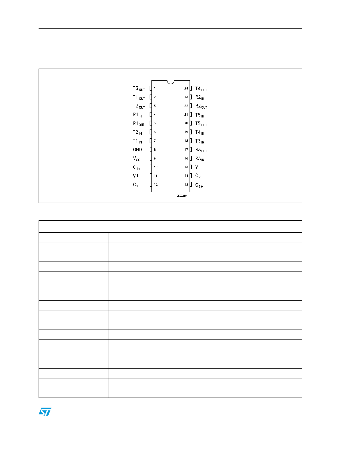
1 Pin configuration
Figure 1. Pin connections (top view)
Table 2. Pin description
Pin N° Symbol Note
1T3
2T1
3T2
OUT
OUT
OUT
4R1
5R1
OUT
6T2
7T1
8 GND Ground
9V
10 C
CC
1+
11 V
12 C
13 C
14 C
1-
2+
2-
15 V
16 R3
17 R3
OUT
RS-232 driver output
RS-232 driver output
RS-232 driver output
RS-232 receiver input
IN
TTL/CMOS receiver output
TTL/CMOS driver input internal pull-up to V
IN
TTL/CMOS driver input internal pull-up to V
IN
4.75V to 5.25V supply voltage
Terminal for positive charge-pump capacitor
2VCC generated by the charge-pump
+
Terminal for negative charge-pump capacitor
Terminal for positive charge-pump capacitor
Terminal for negative charge-pump capacitor
-2VCC generated by the charge-pump
-
RS-232 receiver input
IN
TTL/CMOS receiver output
CC
CC
3/15

Pin configuration ST207EB - ST207EC
Table 2. Pin description
Pin N° Symbol Note
18 T3
19 T4
20 T5
21 T5
22 R2
23 R2
24 T4
IN
IN
OUT
IN
OUT
IN
OUT
TTL/CMOS driver input internal pull-up to V
TTL/CMOS driver input internal pull-up to V
RS-232 driver output
TTL/CMOS driver input internal pull-up to V
TTL/CMOS receiver output
RS-232 receiver input
RS-232 driver output
CC
CC
CC
4/15

ST207EB - ST207EC Maximum ratings
2 Maximum ratings
Table 3. Absolute maximum ratings
Symbol Parameter Value Unit
V
CC
V+ Extra positive voltage (V
Supply voltage -0.3 to 6 V
- 0.3) to 14 V
CC
V- Extra negative voltage -14 to 0.3 V
T
R
T
OUT
R
OUT
T
SHORT
T
STG
IN
IN
Transmitter input voltage range -0.3 to (VCC + 0.3) V
Receiver input voltage range ± 30 V
Transmitter output voltage range (V- - 0.3) to (V+ + 0.3) V
Receiver output voltage range -0.3 to (VCC + 0.3) V
Short circuit duration on t
OUT
Continuous
Storage temperature range -65 to 150 °C
Note: Absolute Maximum Ratings are those values beyond which damage to the device may
occur. Functional operation under these condition is not implied. V+ and V- can have a
maximum magnitude of +7V, but their absolute addition can not exceed 13 V.
5/15
 Loading...