

查询SMA6J188A-TR供应商
Features
■ Peak pulse power:
– 600 W (10/1000 µs)
– 4 kW (8/20 µs)
■ Stand off voltage range: from 5 V to 188 V
■ Unidirectional and bidirectional types
■ Low clamping voltage versus standard series
■ Low leakage current:
– 0.2 µA at 25° C
– 1 µA at 85° C
■ Operating T
■ JEDEC registered package outline
max: 175° C
j
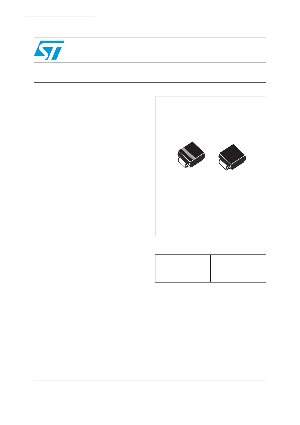
SMA6J
High junction temperature Transil™
A
K
Unidirectional Bidirectional
SMA
(JEDEC DO-214AC)
Description
The SMA6J Transil series has been designed to
protect sensitive equipment against electro-static
discharges according to IEC 61000-4-2, MIL STD
883 Method 3015, and electrical over stress such
as IEC 61000-4-4 & 5. They are also in
accordance with ISO TR 7637-2, SAE J 113 and
DIN 40839 for automotive applications and more
generally for surges below 600 W 10/1000 µs
This Planar technology makes it compatible with
high-end equipment like automotive, medical
equipment or SMPS where low leakage current
and high junction temperature are required to
provide reliability and stability over time. Their low
clamping voltages provides a better safety margin
to protect sensitive circuits with extended life time
expectancy.
Packaged in SMA, this minimizes PCB
consumption (SMA footprint in accordance with
IPC 7531 standard).
Order code
Part number Marking
SMA6JxxA-TR See Ta b l e 6 .
SMA6JxxCA-TR See Ta b l e 6 .
Complies with the following standards:
IEC 61000-4-2 level 4:
15 kV(air discharge)
8 kV(contact discharge)
MIL STD 893G-Method 3015-7: class3B
25 kV HBM (Human Body Model)
TM: TRANSIL is a trademark of STMicroelectronics
February 2007 Rev 1 1/10
www.st.com
10
Characteristics SMA6J
1 Characteristics
Table 1. Absolute ratings (T
= 25° C)
amb
Symbol Parameter Value Unit
P
Peak pulse power dissipation
PP
P Power dissipation on infinite heatsink T
I
FSM
T
T
T
1. For a surge greater than the maximum values, the diode will fail in short-circuit.
Table 2. Thermal resistances
Non repetitive surge peak forward current for
unidirectional types
Storage temperature range -65 to +175 ° C
stg
Operating junction temperature range -55 to +175 ° C
j
Maximum lead temperature for soldering during 10 s 260 ° C
L
(1)
Tj initial = T
amb
amb
= 55° C 4 W
tp = 10 ms
Tj initial = T
amb
600 W
60 A
Symbol Parameter Value Unit
R
th (j-l)
R
th (j-a)
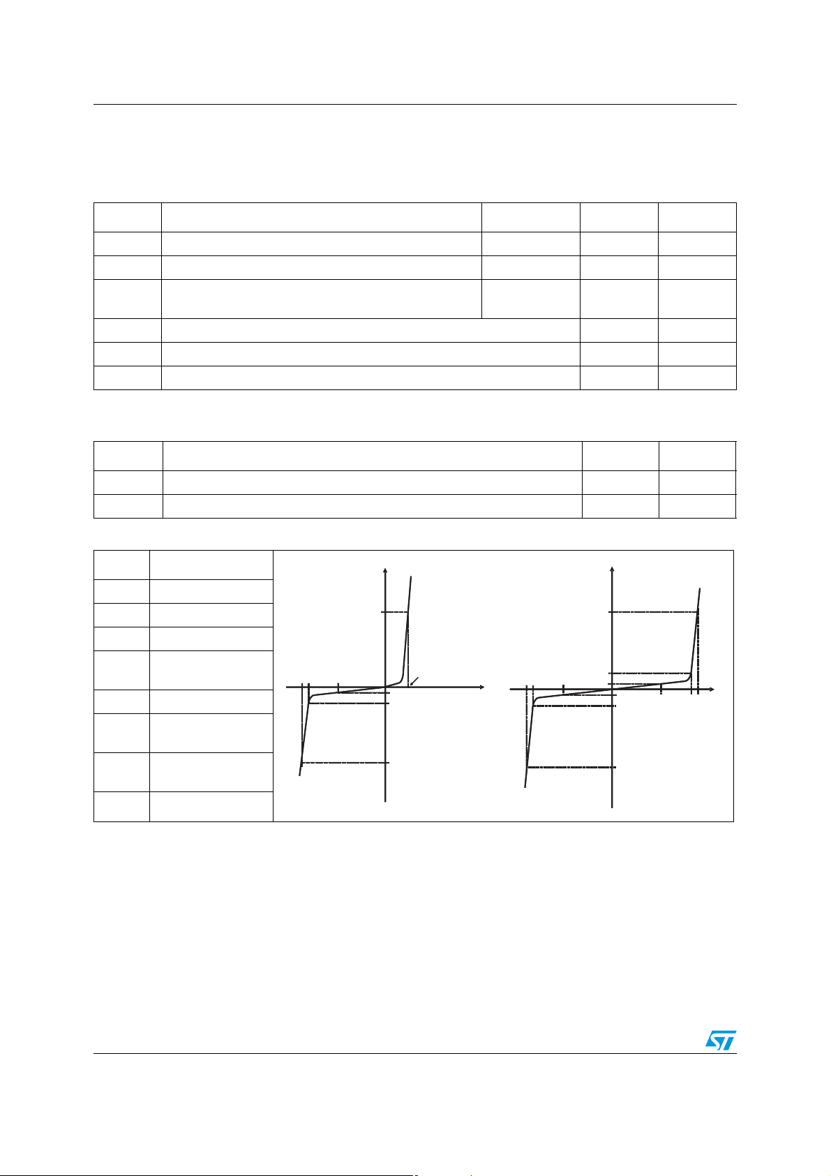
Table 3. Electrical characteristics - definitions (T
Symbol Parameter
V
RM
V
BR
V
CL
I
RM
I
PP
αT
V
F
Junction to leads 30 ° C/W
Junction to ambient on printed circuit on recommended pad layout 120 ° C/W
I
I
amb
= 25° C)
I
I
Stand-off voltage
I
Breakdown voltage
I
I
F
F
I
PP
PP
Clamping voltage
Leakage current
@ V
RM
Peak pulse current
Voltage temperature
VCLVBRV
VCLVBRV
RM
RM
V
V
F
F
I
I
RM
RM
I
I
R
R
V
V
VCLVBRV
VCLVBRV
RM
RM
I
I
R
R
I
I
RM
RM
I
I
VRMVBRV
VRMVBRV
RM
RM
I
I
R
R
coefficient
Unidirectional Bidirectional
I
Forward voltage
drop
I
PP
PP
I
I
PP
PP
V
V
CL
CL
R
Dynamic resistance
D
2/10
SMA6J Characteristics
Type
max@VRM V
I
RM
BR
@I
R
(1)
amb
= 25° C)
VCL @IPP
10/1000 µs
(2)
R
D
10/1000 µs
VCL @IPP
8/20 µs
R
8/20 µs
25° C 85° C min typ max max max max
(2)
D
αT
Table 4. Electrical characteristics - values (T
µA V V mA V A Ω VA Ω 10-4/°C
SMA6J5.0A/CA 10 50 5.0 6.40 6.74 7.07 10 9.1 68 0.029 13.4 298 0.021 5.7
SMA6J6.0A/CA 10 50 6.0 6.70 7.05 7.41 10 9.5 61 0.034 13.7 290 0.022 5.9
SMA6J6.5A/CA 10 50 6.5 7.20 7.58 7.96 10 10.2 56 0.040 14.5 276 0.024 6.1
SMA6J8.5A/CA 10 50 8.5 9.4 9.9 10.4 1 13.3 41.7 0.070 18.7 205 0.041 7.3
SMA6J10A/CA 0.2 1 10 11.1 11.7 12.3 1 15.7 37 0.093 19.6 184 0.040 7.8
SMA6J12A/CA 0.2 1 12 13.3 14.0 14.7 1 18.8 31 0.133 23.5 157 0.056 8.3
SMA6J13A/CA 0.2 1 13 14.4 15.2 15.9 1 20.4 29 0.154 23.9 147 0.054 8.4
SMA6J15A/CA 0.2 1 15 16.7 17.6 18.5 1 23.6 25.1 0.206 27.7 123 0.075 8.8
SMA6J18A/CA 0.2 1 18 20.0 21.1 22.1 1 28.3 21.5 0.288 33.2 102 0.108 9.2
SMA6J20A/CA 0.2 1 20 22.2 23.4 24.5 1 31.4 19.4 0.354 36.8 93 0.132 9.4
SMA6J24A/CA 0.2 1 24 26.7 28.1 29.5 1 37.8 16 0.516 44.3 80 0.184 9.6
SMA6J26A/CA 0.2 1 26 28.9 30.4 31.9 1 40.9 14.9 0.600 47.9 75 0.213 9.7
SMA6J28A/CA 0.2 1 28 31.1 32.7 34.4 1 44.0 13.8 0.697 51.6 68 0.253 9.8
(3)
SMA6J33A/CA 0.2 1 33 36.7 38.6 40.6 1 51.9 11.8 0.963 60.8 57 0.356 10.0
SMA6J40A/CA 0.2 1 40 44.4 46.7 49.1 1 62.8 9.7 1.42 73.6 48 0.511 10.1
SMA6J48A/CA 0.2 1 48 53.3 56.1 58.9 1 75.4 8.1 2.04 88.4 40 0.736 10.3
SMA6J58A/CA 0.2 1 58 64.4 67.8 71.2 1 91.1 6.7 2.97 100 33 0.863 10.4
SMA6J70A/CA 0.2 1 70 77.8 81.9 86.0 1 110 5.5 4.38 120 27 1.27 10.5
SMA6J85A/CA 0.2 1 85 94 99 104 1 134 4.6 6.45 146 22.5 1.85 10.6
SMA6J100A/CA 0.2 1 100 111 117 123 1 157 3.8 9.03 172 19 2.58 10.7
SMA6J130A/CA 0.2 1 130 144 152 159 1 204 3 14.9 223 15 4.24 10.8
SMA6J154A/CA 0.2 1 154 171 180 189 1 242 2.4 22.1 265 12.6 6.00 10.8
SMA6J170A/CA 0.2 1 170 189 199 209 1 275 2.2 30.0 292 11.3 7.39 10.8
SMA6J188A/CA 0.2 1 188 209 220 231 1 328 2 48.5 323 10.3 8.97 10.8
1. Pulse test: tp <50ms.
2. To calculate maximum clamping voltage at other surge currents, use the following formula
V
= RD x IPP + V
CLmax
3. To calculate VBR versus junction temperature, use the following formula:
VBR @ Tj = VBR @ 25 ° C x (1 + αT x (Tj - 25))
BRmax
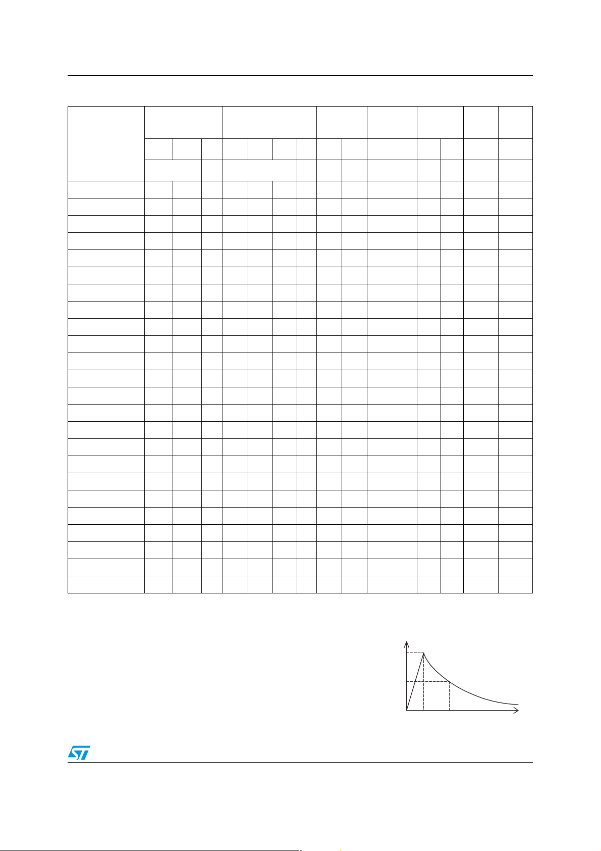
100
50
%I
PP
Repetitive peak pulse current
tr = rise time (µs)
tp = pulse duration time (µs)
0
t
t
r
p
t
3/10
 Loading...