

Page 1

AN5480
Application note
How to build a Sigfox
™
application with STM32CubeWL
Introduction
This application note provides guideline to build specific Sigfox™ applications based on STM32WL Series microcontrollers. This
document groups together the most important information and lists the aspects to be addressed.
Sigfox™ is a type of wireless telecommunication network designed to allow long-range communication at very low bit rates, and
to enable the use of long-life battery-operated sensors. The Sigfox Stack™ library manages the channel access and security
protocol that ensures interoperability with the Sigfox™ network.
The application based on the NUCLEO_WL55JC, STM32WL Nucleo-64 boards (order code NUCLEO‑WL55JC1 for
high‑frequency band), and firmware in the STM32CubeWL MCU Package is Sigfox Verified™.
Sigfox™ application main features are:
• Application integration ready
•
RC1, RC2, RC3c, RC4, RC5, RC6 and RC7 Sigfox Verified
•
Sigfox™ Monarch (STMicroelectronics algorithm patented)
• Extremely low CPU load
• No latency requirements
• Small STM32 memory footprint
• Utilities services provided
The firmware of the STM32CubeWL MCU Package is based on the STM32Cube HAL drivers.
™
AN5480 - Rev 3 - January 2021
For further information contact your local STMicroelectronics sales office.
www.st.com
Page 2
1 Overview
The STM32CubeWL runs on STM32WL Series microcontrollers based on the Arm® Cortex®-M processor.
Note: Arm is a registered trademark of Arm Limited (or its subsidiaries) in the US and/or elsewhere.
Table 1. Acronyms
Acronym Definition
CS Carrier sense
DC Duty cycle
FH Frequency hopping
IoT Internet of things
LBT Listen before talk
PAC Porting authorization code
POI Point of interest
RC Region configuration
RSA Radio Sigfox analyzer
RSSI Receive signal strength indicator
Rx Reception
SDR Software-defined radio
Tx Transmission
AN5480
Overview
AN5480 - Rev 3
page 2/77
Page 3

2 Sigfox standard
This section provides a general Sigfox overview, focusing, in particular, the Sigfox end-device.
Sigfox is a wireless telecommunication network operator designed to allow long range communication at a low
bit‑rate enabling long-life battery operated sensors. The firmware of the STM32CubeWL MCU Package includes
the Sigfox Stack library.
Sigfox limits the use of its network to 144 messages per day and per device. Each message can be from 1 bit up
to 12 bytes.
2.1 End-device hardware architecture
The end device is the STM32WL55JC microcontroller mounted on NUCLEO-WL55JC board.
This MCU, with integrated sub-GHZ radio operating in the150 - 960 MHz ISM band, belongs to the
STM32WL Series that include microcontrollers with different memory sizes, packages and peripherals.
2.2 Regional radio resource
The European, North American and Asian markets have different spectrum allocations and regulatory
requirements. Sigfox has split requirements in various RCs (region configurations) listed in the table below.
AN5480
Sigfox standard
Table 2. Region configurations
RC Countries
RC1 Europe, Oman, Lebanon, South Africa, Kenya
RC2 USA, Canada, Mexico
RC3c Japan
RC4 Brazil, Colombia, Peru, New–Zealand, Australia and Singapore
RC5 South Korea
RC6 India
RC7 Russia
AN5480 - Rev 3
page 3/77
Page 4
AN5480
Rx/Tx radio time diagram
The table below provides an overview of the regulatory requirements for the region configurations.
Table 3. RF parameters for region configurations
RF parameter RC1 RC2 RC3c RC4 RC5 RC6 RC7
Frequency band downlink
(MHz)
Frequency band uplink (MHz) 868.130 902.2 923.2 920,8 923.3 865.2 868.8
Uplink modulation DBPSK
Downlink modulation GFSK
Uplink data‑rate 100 600 100 600 100 100 100
Down-link data‑rate 600
Max output power (dBm) 14 22 13 22 13 13 14
Medium access
CS center frequency (MHz)
CS threshold (dBm) -80 NA -65
869.525 905.2 922.2 922.3 922.3 866.3 869.1
Duty
cycle 1%
Frequency
hopping
Max on time
400 ms/20 s
NA
Carrier
sense
923.2 NA 923.3
Frequency
hopping
Max on time
400 ms/20 s
Carrier
sense
Duty cycle 1%
NACS bandwidth (kHz) 200 NA 200
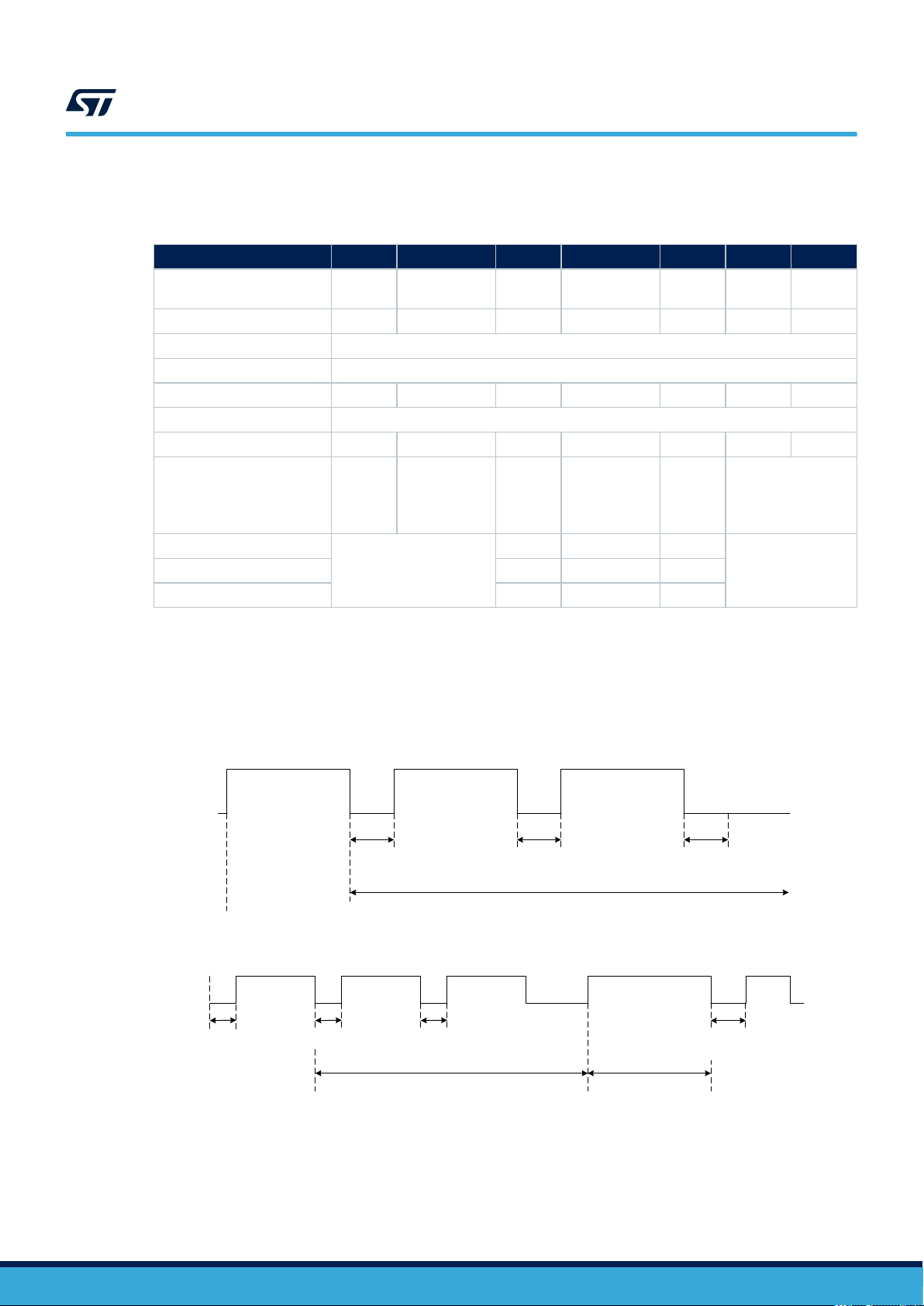
2.3 Rx/Tx radio time diagram
The end device transmits data to the network in an asynchronous manner. This is due to the fact that
transmission data is only sent per device-report event. The figures below depict the timing sequences with and
without a downlink.
Tx1 Tx2 Tx3
Interframe Tx
Figure 2. Timing diagram for uplink with downlink
Tx1
StartTx
delay
Interframe TRx
Figure 1. Timing diagram for uplink only
Interframe Tx
End timeout
Tx2 Tx3 Rx window TxOOB
Interframe TRx
Rx delay
Rx timeout
Interframe Tx
OOB_ACK
delay
Note: The presence of a downlink only depends on device configuration.
The three transmissions Tx1, Tx2 and Tx3 contain the same payload information. These consecutive
transmissions only maximize the probability of a correct reception by the network. When the device observes
good link quality to the network, it may decide to send only Tx1 to save power consumption only if downlink frame
is requested. The API to select preferred scheme is described in Section 6.1.2 Send frames/bits.
AN5480 - Rev 3
page 4/77
Page 5
AN5480
Listen before talk (LBT)
The timings shown in the previous figures are detailed in the table below for the various regional configurations.
Table 4. Timings
2.4
RC StartTx delay
RC1
RC2 10 s
RC3c
RC4 10 s 500 ms 20 s 25 s
RC5
RC6
RC7
0 s 500 ms 20 s 25 s
100 ms max
(start LBT)
100 ms max
(LBT)
0 s 500 ms 20 s 25 s
Interframe
Tx/TRx
500 ms + LBT 19 s 34 s
500 ms + LBT 19 s 34 s
Rx delay Rx timeout
OOB_ACK
delay
1.4 s
End timeout
NA
NA
The Tx periods depend on the number of bytes sent and on the RC zone:
• It takes 10 ms to send a bit in RC1 and RC3c.
• It takes 1.66 ms to send a bit in RC2 and RC4.
A message can be 26-byte long at the most (including sync word, header, and payload data). Therefore, for RC1,
a Tx period can be maximum 26 x 8 x 10 ms = 2.08 s.
Listen before talk (LBT)
In RC3c and RC5, LBT is mandatory before any transmission.
In RC3c, the device must listen and check if the channel is free. The channel is considered as free if the power
within a 200 kHz bandwidth stays below -80 dBm (CS threshold) for 5 ms.
When the channel is free, the device starts a transmission. The transmission is not started otherwise.
2.5 Monarch
Monarch is a Sigfox beacon placed at a point of interest (POI). The signal of the Sigfox beacon is emitted at a
frequency allowed by the region the POI belongs to. The beacon contains region configuration (RC) information
that a Monarch‑capable device can demodulate.
Upon reception of this information, the Monarch-capable device is able to switch automatically to the right RC and
send information to the network.
The Monarch feature allows a Sigfox IoT device to roam seamlessly across the world.
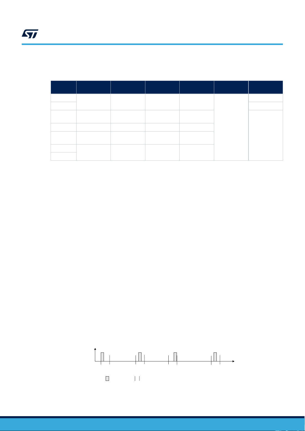
2.5.1 Monarch signal description
The Monarch signal is sent at POI every 5 minutes plus a random back-off period of 10 seconds. The frequency
of the beacon is region specific. The beacon lasts in total 400 ms. If a device clock is set, it is hence possible to
open a scan window only when the Monarch signal is present to reduce current consumption of the end device.
Time
(0:2:30)
Figure 3. Monarch beacon
Time
(0:7:30)
Beacon time boundBeacon
Time
(0:12:30)
Time
(0:17:30)
Time
(ss:mm:ss)
AN5480 - Rev 3
page 5/77
Page 6
AN5480
Monarch
The signal is OOK modulated, meaning the signal is either ON or OFF. The modulation frequency is specified to
16384 Hz (half an RTC clock). The signal is ON for one sample and then OFF. It is ON with a periodicity of 11, 13
or 16 (16384 Hz) samples. Hence the following OOK frequency dF are possible:
• dF1 = 16384 / 16 = 1024 Hz
• dF2 = 16384 / 13 = 1260.3 Hz
• dF3 = 16384 / 11 = 1489.4 Hz
The 400 ms of the Monarch pattern is composed of two sub-patterns:
• The pattern1 lasts 362 ms at a specific dF.
• The pattern2 lasts 38 ms at another specific dF.
Table 5. Monarch signal characteristics versus RC
RC Monarch frequency (Hz) Pattern1 dF (Hz) Pattern2 dF (Hz)
RC1 869 505 000
1024 1260.3RC2 905 180 000
RC3
RC4 1260.3
RC5
RC6 866 250 000
RC7 869 160 000 1260.3
922 250 000
1024
1489.4
2.5.2 Monarch signal demodulation
When a device starts to scan a Monarch signal, the device sweeps during 5 mn onto all Monarch frequencies
listed in Table 5: this is called the sweep period.
Note: If the time is known, the sweep time may be reduced about 10 s + some clock drift.
During this period, the device tries to match with one of the pattern1. When a match is found, the device exits
the sweep period to enter a second period called the window period during for 400 ms. The device sets its RF
frequency where the pattern1 match occurred. The device then tries to match the pattern2 to confirm a Monarch
beacon is found.
AN5480 - Rev 3
page 6/77
Page 7

3 SubGHz HAL driver
This section focuses on the SubGHz HAL (other HAL functions such as timers or GPIO are not detailed).
The SubGHz HAL is directly on top of the sub-GHz radio peripheral (see Figure 1).
The SubGHz HAL driver is based on a simple one-shot command-oriented architecture (no complete processes).
Therefore, no LL driver is defined.
This SubGHz HAL driver is composed the following main parts:
• Handle, initialization and configuration data structures
• Initialization APIs
• Configuration and control APIs
• MSP and events callbacks
• Bus I/O operation based on the SUBGHZ_SPI (Intrinsic services)
As the HAL APIs are mainly based on the bus services to send commands in one-shot operations, no functional
state machine is used except the RESET/READY HAL states.
3.1 SubGHz resources
The following HAL SubGHz APIs are called at the initialization of the radio:
• Declare a SUBGHZ_HandleTypeDef handle structure.
• Initialize the sub-GHz radio peripheral by calling the HAL_SUBGHZ_Init(&hUserSubghz) API.
• Initialize the SubGHz low-level resources by implementing the HAL_SUBGHZ_MspInit() API:
– PWR configuration: Enable wakeup signal of the sub-GHz radio peripheral.
– NVIC configuration:
◦ Enable the NVIC radio IRQ interrupts.
◦ Configure the sub-GHz radio interrupt priority.
The following HAL radio interrupt is called in the stm32wlxx_it.c file:
• HAL_SUBGHZ_IRQHandler in the SUBGHZ_Radio_IRQHandler.
AN5480
SubGHz HAL driver
3.2 SubGHz data transfers
The Set command operation is performed in polling mode with the HAL_SUBGHZ_ExecSetCmd(); API.
The Get Status operation is performed using polling mode with the HAL_SUBGHZ_ExecGetCmd(); API.
The read/write register accesses are performed in polling mode with following APIs:
• HAL_SUBGHZ_WriteRegister();
• HAL_SUBGHZ_ReadRegister();
• HAL_SUBGHZ_WriteRegisters();
• HAL_SUBGHZ_ReadRegisters();
• HAL_SUBGHZ_WriteBuffer();
• HAL_SUBGHZ_ReadBuffer();
AN5480 - Rev 3
page 7/77
Page 8
BSP STM32WL Nucleo-64 boards
4 BSP STM32WL Nucleo-64 boards
This BSP driver provides a set of functions to manage:
• an application dependent part, implementing external control of on-board components: RF switches, TCXO,
RF losses and LEDs/sensors available on the STM32WL Nucleo-64 board (NUCLEO-WL55JC)
• a fixed part implementing the internal radio accesses (reset, busy and the NVIC radio IRQs)
Note: In the current implementation, due to STM32CubeMX limitation, the firmware does not use BSP files but
radio_board_if.c/.h for radio related items, and board_resources.c/.h for LED and push buttons. The
choice between the two implementations is done into Core/Inc/platform.h by selecting USE_BSP_DRIVER
or MX_BOARD_PSEUDODRIVER.
4.1 Frequency band
Two types of Nucleo board are available on the STM32WL Series:
• NUCLEO-WL55JC1: high-frequency band, tuned for frequency between 865 MHz and 930 MHz
• NUCLEO-WL55JC2: low-frequency band, tuned for frequency between 470 MHz and 520 MHz
Obviously, If the user tries to run a firmware compiled at 868 MHz on a low-frequency band board, very poor RF
performances are expected.
The firmware does not check the band of the board on which it runs.
AN5480
4.2 RF switch
The STM32WL Nucleo-64 board embeds an RF 3-port switch (SP3T) to address, with the same board, the
following modes:
• high-power transmission
• low-power transmission
• reception
int32_t BSP_RADIO_Init(void)
BSP_RADIO_ConfigRFSwitch(BSP_RADIO_Switch_TypeDef Config)
int32_t BSP_RADIO_DeInit (void)
int32_t BSP_RADIO_GetTxConfig(void)
The RF states versus the switch configuration are given in the table below.
RF state
High-power transmission Low High High
Low-power transmission High High High
Reception High Low High
Table 6. BSP radio switch
Function Description
Initializes the RF switch.
Configures the radio switch.
De-initializes the RF switch.
Returns the board configuration:
high power, low power or both.
Table 7. RF states versus switch configuration
FE_CTRL1 FE_CTRL2 FE_CTRL3
AN5480 - Rev 3
page 8/77
Page 9

4.3 RF wakeup time
The sub-GHz radio wakeup time is recovered with the following API.
uint32_t BSP_RADIO_GetWakeUpTime(void)
The user must start the TCXO by setting the command RADIO_SET_TCXOMODE with a timeout depending of the
application.
The timeout value can be updated in stm32wlxx_nucleo_conf.h. Default template value is defined below.
#define RF_WAKEUP_TIME 10U
4.4 TCXO
Various oscillator types can be mounted on the user application. On the STM32WL Nucleo-64 boards, a TCXO
(temperature compensated crystal oscillator) is used to achieve a better frequency accuracy.
AN5480
RF wakeup time
Table 8. BSP radio wakeup time
Function Description
Returns RF_WAKEUP_TIME value.
uint32_t BSP_RADIO_IsTCXO (void)
The user can change this value in stm32wlxx_nucleo_conf.h:
#define IS_TCXO_SUPPORTED 1U
4.5 Power regulation
Depending on the user application, a LDO or an SMPS (also named DCDC) is used for power regulation.
An SMPS is used on the STM32WL Nucleo-64 boards.
uint32_t BSP_RADIO_IsDCDC (void)
The user can change this value in stm32wlxx_nucleo_conf.h:
#define IS_DCDC_SUPPORTED 1U
The SMPS on the board can be disabled by setting IS_DCDC_SUPPORTED to 0.
Table 9. BSP radio TCXO
Function Description
Returns IS_TCXO_SUPPORTED value.
Table 10. BSP radio SMPS
Function Description
Returns IS_DCDC_SUPPORTED value.
AN5480 - Rev 3
page 9/77
Page 10
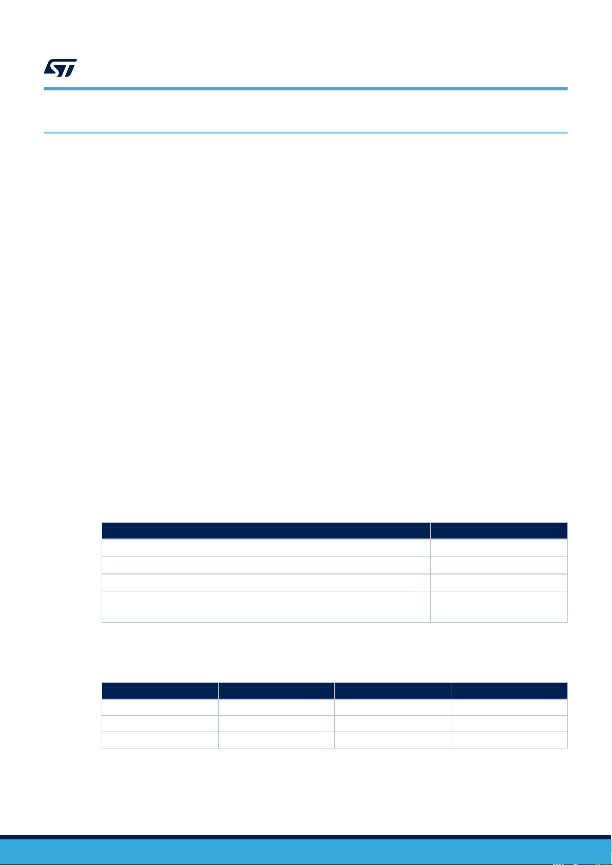
4.6 STM32WL Nucleo-64 board schematic
The figure below details the STM32WL Nucleo-64 board, MB1389 reference board schematic, highlighting some
useful signals:
• control switches on PC4, PC5 and PC3
• TCXO control voltage PIN on PB0
• debug lines on PB12, PB13 and PB14
• system clock on PA8
• SCK on PA5
• MISO on PA6
• MOSI on PA7
Figure 4. NUCLEO-WL55JC schematic
Data transaction:
SKC, MOSI, MISO
AN5480
STM32WL Nucleo-64 board schematic
Control switchs
1 and 2
Debug line 2 and 3
Debug line 1
System clock
TCXO control
voltage
Control
switch 3
AN5480 - Rev 3
page 10/77
Page 11

AN5480
Sigfox Stack description
5 Sigfox Stack description
The firmware of the STM32CubeWL MCU Package includes STM32WL resources such as:
• STM32WLxx Nucleo drivers
• STM32WLxx HAL drivers
• Sigfox middleware
• SubGHz physical layer middleware
• Sigfox application example
• Utilities
The Sigfox middleware for STM32 microcontrollers is split into several modules:
• Sigfox Core library layer module
• Sigfox crypto module
• Sigfox Monarch (ST algorithm patent)
The Sigfox Core library implements a Sigfox medium access controller that interfaces with the Cmac library
encrypting uplink payload and verifying downlink payload. The Cmac library interfaces with the Credentials library
holding the cryptographic functions. This medium access controller also interfaces with the ST Monarch library.
The Sigfox Core library interfaces also with i.e rf_api.c.and and mcu_api,cm porting files in the user
directory. It is not advised to modify these files.
The Sigfox Core, Sigfox test, cryptographic and Monarch library modules are provided in compiled object.
The libraries have been compiled with wchar32 and 'short enums'. These settings are used by default in IAR
Embedded workbench and STM32CubeIDE.
For μVision Keil, specific care must be taken. Tickbox 'Short enums/wchar' must be unchecked and 'fshort
-enums' must be added in 'Misc Controls' field.
Note: For dual-core applications, these settings must be applied to both cores to guaranty same enum formatting.
5.1
Sigfox certification
The system including the NUCLEO-WL55JC board and the STM32CubeWL firmware modem application has
been verified by Sigfox Test Lab and passed the Sigfox Verified certification.
Nevertheless, the end product based on a STM32WL Series MCU must pass again the Sigfox Verified and the
Sigfox Ready™ certification before the end-product commercialization.
AN5480 - Rev 3
page 11/77
Page 12
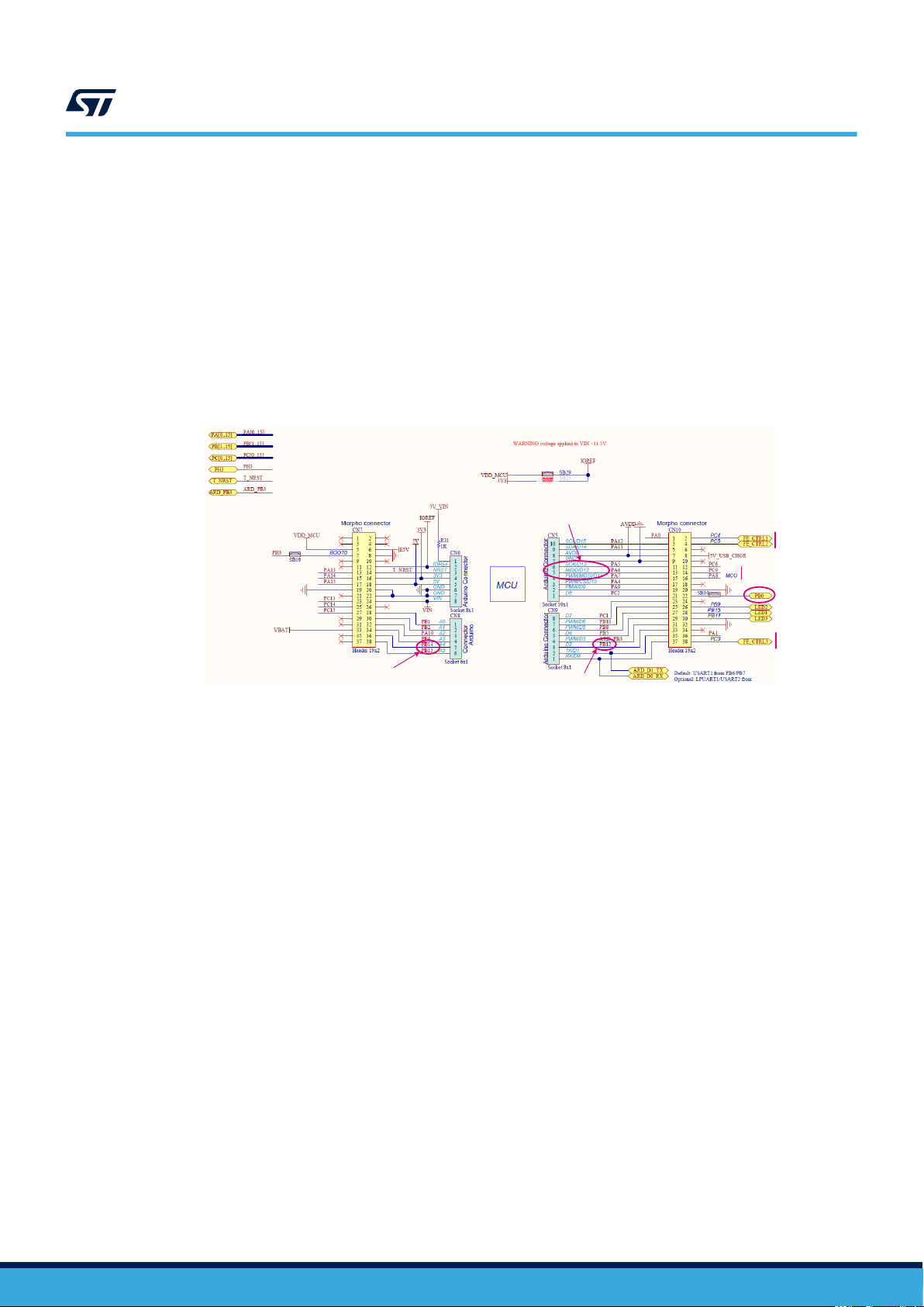
5.2 Architecture
5.2.1 Static view
The figure below details the main design of the firmware for the Sigfox application.
radio.h
AN5480
Architecture
Figure 5. Static Sigfox architecture
Sigfox application
(AT_Slave or PushButton)
Sigfox middleware
rf_protocol_api.h
Sigfox test
library
rf_api
Utilities
NVM (E2P)
Timer server
Sequencer
Debug trace
Low-power
mode
Cmac
library
se_api
sigfox_api.h
Monarch
library
mn_api
Sigfox
library
SubGHz_Phy middleware
radio.c
radio_driver.c
mcu_api
Board support package (BSP)
Hardware abstraction layer APIs (HAL)
NVIC SubGHz RCC GPIO RTC
Sub-GHz radio system peripheral
The HAL uses STM32Cube APIs to drive the hardware required by the application.
The RTC provides a centralized time unit that continues to run even in the low-power Stop mode. The RTC alarm
is used to wake up the system at specific times managed by the timer server.
The Sigfox Core library embeds the medium access controller (MAC) as well as some security functions (see
Section 6.1 Sigfox Core library for more details).
The application is built around an infinite loop including a scheduler. The scheduler processes tasks and events.
When nothing remains to be done, the scheduler transitions to idle state and calls the low-power manager.
Typical application examples:
• AT layer to interface with external host (refer to Section 11.2 AT modem application)
• application reading and sending sensor data upon an action (refer to Section 11.3 PushButton application)
AN5480 - Rev 3
page 12/77
Page 13
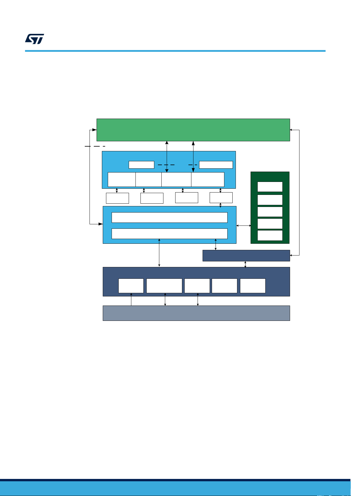
5.2.2 Dynamic view
The message sequence chart (MSC) in the figure below depicts the dynamic calls between APIs in Tx mode (for
one transmission).
AN5480
Architecture
Figure 6. Transmission MSC
Application
SIGFOX_API_
send_frame
Sigfox Core
library
rf_mode: SFX_RF_MODE_TX
RF_API_change_
frequency(frequency)
MANUF_API
RF_API_init
Radio.SetChannel
(frequency)
Get EEPROM power
Radio.SetTxConfig
(MODEM_SIGFOX_TX,
Power, datarate,
timeout)
Radio.Send
(stream, size)
CFG_SEQ_Evt_TxTimout
Callback SUBGHZ_Radio_IRQHandler
CFG_SEQ_Evt_TxTimout
RF_API_stop Radio.Sleep()
Radio Idle
Return
Interrupt
SEQ_WaitEvt
Tx ON
MCU stop
SEQ_SetEvt
When a downlink window is requested, an Rx sequence is started after Rxdelay is elapsed (see Figure 2. Timing
diagram for uplink with downlink).
When Rxdelay is elapsed, the sequence detailed in the figure below occurs.
Sigfox Core
library
rf_mode: SFX_RF_MODE_RX
RF_API_change_
frequency(frequency)
MCU_API_timer_start
RF_API_wait_frame
MCU_API_timer_stop
Figure 7. Reception MSC
MANUF_API
RF_API_init
RF_API_stop Radio.Sleep()
Radio.SetTxConfig
(MODEM_SIGFOX_RX)
RF_API_change_
frequency(frequency)
T 25 s
onTimerTImoutEvt
CFG_SEQ_Evt_TxTimout
Radio.RxBoosted(0)
CFG_SEQ_Evt_TxTimout
Callback SUBGHZ_Radio_IRQHandler
CFG_SEQ_Evt_TxTimout
T
Radio Idle
Return
Interrupt
SEQ_WaitEvt
Rx ON
MCU stop
SEQ_SetEvt
AN5480 - Rev 3
page 13/77
Page 14

5.3 Required STM32 peripherals to drive the radio
Sub-GHz radio
The sub-GHz radio peripheral is accessed through the stm32wlxx_hal_subghz HAL.
The sub-GHz radio issues an interrupt through SUBGHZ_Radio_IRQHandler NVIC, to notify a TxDone or
RxDone event. More events are listed in the product reference manual.
RTC
The RTC (real-time clock) calendar is used as 32-bit counter running in all power modes from the 32 kHz
external oscillator. By default, the RTC is programed to provide 1024 ticks (sub-seconds) per second. The RTC is
programed once at hardware initialization when the MCU starts for the first time. The RTC output is limited to a
32-bit timer that corresponds to about a 48-day period.
Caution: When changing the tick duration, the user must keep it below 1 ms.
LPTIM
The LPTIM (low-power timer) is used for Monarch only. The LPTIM is set when a Monarch scan is requested,
uses the LSE clock and issues an interrupt at 16384 Hz.
AN5480
Required STM32 peripherals to drive the radio
AN5480 - Rev 3
page 14/77
Page 15

6 Sigfox middleware programming guidelines
6.1 Sigfox Core library
Embedded applications using the Sigfox Core library call SIGFOX_APIs to manage communication.
Table 11. Application level Sigfox APIs
Function Description
sfx_error_t SIGFOX_API_get_device_id
(sfx_u8 *dev_id);
sfx_error_t SIGFOX_API_get_initial_pac
(sfx_u8 *initial_pac);
sfx_error_t SIGFOX_API_open
(sfx_rc_t *rc);
sfx_error_t SIGFOX_API_close(void);
sfx_error_t SIGFOX_API_send_frame
(sfx_u8 *customer_data,
sfx_u8 customer_data_length,
sfx_u8 *customer_response,
sfx_u8 tx_repeat,
sfx_bool initiate_downlink_flag);
sfx_error_t SIGFOX_API_send_bit
(sfx_bool bit_value,
sfx_u8 *customer_response,
sfx_u8 tx_repeat,
sfx_bool initiate_downlink_flag);
sfx_error_t SIGFOX_API_set_std_config
(sfx_u32 config_words[3],
sfx_bool timer_enable);
Copies the ID of the device to the pointer given in parameter.
The ID is 4‑byte long and in hexadecimal format.
Gets the value of the PAC stored in the device. This value is
used when the device is registered for the first time on the
backend. The PAC is 8‑byte long.
Initializes the library and saves the input parameters once
(cannot be changed until SIGFOX_API_close() is
called)
– rc is a pointer on the radio configuration zone. It is
mandatory to use already existing defined RCs.
Closes the library and stops the RF.
Sends a standard Sigfox frame with customer payload.
• customer_data cannot exceed 12 bytes
• customer_data_length: length in bytes
• customer_response: received response
• tx_repeat:
– when 0, sends one Tx.
– when 1, sends three Tx.
• initiate_downlink_flag: if set, the frame sent
is followed by a receive downlink frame and an out-ofband Tx frame (voltage, temperature and RSSI).
Sends a standard Sigfox™ frame with null customer payload
(shortest frame that Sigfox library can generate).
• bit_value: bit sent
• customer_response: received response
• tx_repeat:
– when 0, sends one Tx.
– when 1, sends three Tx.
• initiate_downlink_flag: if set, the frame sent
is followed by a receive downlink frame and an out-ofband Tx frame (voltage, temperature and RSSI).
Configures specific variables for standard. Parameters have
different meanings whether in FH or LBT mode.
Note: this function has no influence in DC (see
Section 11.2.21 ATS400 - Enabled channels for FCC for
details).
AN5480
Sigfox middleware programming guidelines
AN5480 - Rev 3
Secondary APIs are described in sigfox_api.h. The library can be found in the
Middlewares\Third_Party\SigfoxLib directory.
page 15/77
Page 16

6.1.1 Open the Sigfox library
ST_SIGFOX_API_open must be called to initialize the Sigfox library before any other operation is performed.
This API requires the RC argument number representing the radio configuration zone (see Section 2.2 Regional
radio resource).
For radio control zones 2 and 4, the FCC (federal communications commission) requires frequency hopping so
the transmission frequency is not fixed (see Section 6.1.3 Set standard configuration for more details on how to
map the macro channels).
6.1.2 Send frames/bits
ST_SIGFOX_API_send_frame is the main Sigfox library function. This blocking function handles message
exchange between the end node and the base stations.
An important parameter of this function is the initiate_downlink_flag that selects different transmission
behaviors:
• initiate_downlink_flag = 0: The library requests only uplink frame. The sent frame is transmitted
once if tx_repeat = 0, or three times if tx_repeat = 1, with a 500 ms pause (see Figure 1).The
transmit payload can be maximum 12‑byte long.
• initiate_downlink_flag = 1: The frame to be sent is transmitted three times with a 500 ms
pause. A 25 s Rx window then opens 20 s after the end of the first repetition (see Figure 2). If the
reception is successful, the received 8-byte downlink frame is stored in the buffer location indicated by the
customer_response buffer.
AN5480
Sigfox Core library
6.1.3 Set standard configuration
The FCC allows the transmitters to choose certain macro channels to implement a frequencyhopping pattern authorized by the standard. The channel map is specified in the first argument of
SIGFOX_API_set_std_config, that consists of an array of three 32-bit configuration words.
A macro-channel consists of six micro channels centered about the center frequency of the macro channel and
separated by 25 kHz. For example, in the 902.2 MHz macro channel, the six micro channels are 902.1375 MHz,
902.1625 MHz, 902.1875 MHz, 902.2125 MHz, 902.2375 MHz, and 902.2625 MHz.
A typical Sigfox frame lasts between 200 ms and 350 ms at 600 bit/s, and FCC mandates a max dwell time of
400 ms. A transmitter cannot return to a given channel before 20 s. Therefore, at least 20 / 0.4 = 50 channels
must be used for continuous transmission.
Actually, a device only transmits a few frames per day (144 messages maximum). Enabling one macro channel
only and inserting 10 s delays between two groups of three repeated frames (one frame per micro channel means
six micro channels) pass the regulation limits.
AN5480 - Rev 3
page 16/77
Page 17

AN5480
Sigfox Core library
Each bit of the config_words[0,1,2] array represents a macro channel according to the mapping described in the
table below.
Table 12. Macro channel mapping
Bit
0 902.2 911.8 921.4
1 902.5 912.1 921.7
2 902.8 912.4 922
3 903.1 912.7 922.3
4 903.4 913 922.6
5 903.7 913.3 922.9
6 904 913.6 923.2
7 904.3 913.9 923.5
8 904.6 914.2 923.8
9 904.9 914.5 924.1
10 905.2 914.8 924.4
11 905.5 915.1 924.7
12 905.8 915.4 925
13 906.1 915.7 925.3
14 906.4 916 925.6
15 906.7 916.3 925.9
16 907 916.6 926.2
17 907.3 916.9 926.5
18 907.6 917.2 926.8
19 907.9 917.5 927.1
20 908.2 917.8 927.4
21 908.5 918.1 927.7
22 908.8 918.4 928
23 909.1 918.7 928.3
24 909.4 919 928.6
25 909.7 919.3 928.9
26 910 919.6 929.2
27 910.3 919.9 929.5
28 910.6 920.2 929.8
29 910.9 920.5 930.1
30 911.2 920.8 930.4
31 911.5 921.1 930.7
config_words[0]
Frequency mapping (MHz)
config_words[1]
Frequency mapping (MHz)
config_words[2]
Frequency mapping (MHz)
AN5480 - Rev 3
A macro channel is only enabled when the corresponding config_words[x] bit is set to 1. For example, bit 0 of
config_words[0] corresponds to channel 1 while bit 30 of config_words[1] corresponds to channel 63. At least nine
macro channels must be enabled to meet the FCC specifications.
page 17/77
Page 18

In the following long message configuration example, channels 1 to 9 are enabled with frequencies ranging from
902.2 MHz to 904.6 MHz:
• config_words[0] = [0x0000 01FF]
• config_words[1] = [0x0000 0000]
• config_words[2] = [0x0000 0000]
By default, the Sigfox application sets one macro channel with timer_enable = 1. The macro channel 1 in
RC2 has a 902.2 MHz operational frequency and the macro channel 63 in RC4 has a 920.8 MHz operational
frequency). This is the short message configuration operational for Sigfox (see defined RCx_SM_CONFIG value in
sigfox_api.h file).
A delay (timer_enable) is implemented to avoid one micro channel to be re-used with an interval lower
than 20 s. When using one macro channel only (six micro channels) performing three repetitions, this delay
corresponds to 10 s. When using two macro channels (12 micro channels), the delay automatically becomes 5 s.
For certification test purposes, timer_enable may be set to 0, but must be set to 1 otherwise. The default
settings can nevertheless be modified using the ATS400 command (Section 11.2.21 ) to speed up the
certification process.
6.2 Sigfox Addon RF protocol library
This library is used to test the device for Sigfox Verified certification. Ultimately, this library can be removed from
the build once certified.
AN5480
Sigfox Addon RF protocol library
Table 13. Sigfox Addon Verified library
Function Description
sfx_error_t
ADDON_SIGFOX_RF_PROTOCOL_API_test_mode
(sfx _rc_enum_t rc_enum, sfx_test_mode_t test_mode);
Executes the test modes needed for the
Sigfox Verified certification:
• rc_enum: rc at which the test
mode is run
• test_mode: test mode to run
sfx_error_t
ADDON_SIGFOX_RF_PROTOCOL_API_monarch_test_ mode
(sfx_rc_enum_t rc_enum, sfx_test_mode_t test_mode,
This function executes the Monarch test
modes needed for Sigfox RF and protocol
tests.
sfx_u8 rc_capabilities);
This library is located in Middlewares\Third_Party\Sgfx\SigfoxLibTest\.
AN5480 - Rev 3
page 18/77
Page 19

6.3 Cmac library
The Cmac library stores the keys, the PAC and the IDs.
sfx_u8 SE_API_get_device_id
(sfx_u8 dev_id[ID_LENGTH]);
sfx_u8 SE_API_get_initial_pac (sfx_u8 *initial_pac);
sfx_u8 SE_API_secure_uplink_message
(sfx_u8 *customer_data,
sfx_u8 customer_data_length,
sfx_bool initiate_downlink_frame,
sfx_se_frame_type_t frame_type,
sfx_bool *send_rcsync,
sfx_u8 *frame_ptr, sfx_u8 *frame_length);
sfx_u8 SE_API_verify_downlink_message
(sfx_u8 *frame_ptr, sfx_bool *valid);
AN5480
Cmac library
Table 14. Cmac APIs
Function Description
This function copies the device ID in
dev_id.
Gets the initial PAC.
Generates an uplink frame bitstream.
Authenticates a received message and
decrypts its payload.
The Cmac library is located in directory \Middlewares\Third_Party\Sgfx\Crypto.
Note: • This library interfaces the se_nvm functions to store/retrieve SFX_SE_NVMEM_BLOCK_SIZE bytes from the
non-volatile memory.
• se_api.h is the interface to the Sigfox secure element that can be either a physical secure element, or
emulated by firmware with the Cmac library and the Credentials library.
AN5480 - Rev 3
page 19/77
Page 20

6.4 Credentials library
The Credentials library can access the keys, the PAC and the IDs. It can also encrypt data with the Sigfox key.
void CREDENTIALS_get_dev_id(uint8_t* dev_id);
void CREDENTIALS_get_initial_pac (uint8_t* pac);
sfx_bool CREDENTIALS_get_payload_encryption_fl
ag(void);
sfx_error_t CREDENTIALS_aes_128_cbc_encrypt
(uint8 _t* encrypted_data, uint8_t* data_to_encrypt,
uint8_t block_len);
sfx_error_t CREDENTIALS_wrap_session_key
(uint8_t *data, uint8_t blocks)
sfx_error_t
CREDENTIALS_aes_128_cbc_encrypt_with_session_key
(uint8_t *encrypted_data,
uint8_t *data_to_encrypt, uint8_t blocks)
AN5480
Credentials library
Table 15. Credentials APIs
Function Description
Gets the device ID.
Gets the device initial PAC.
Gets the encryption flag. Sets
to false by default (see
Section 11.2.10 ATS411 - Payload
encryption).
Encrypts data with the secret
key. The secret key can be
set to CMAC_KEY_PRIVATE
or CMAC_KEY_PUBLIC (see
Section 11.2.9 ATS410 - Encryption
key).
Derives a session key based on the
Sigfox secret key
Encrypts data with the session key.
6.5 Monarch library
The Monarch APIs are defined in sigfox_monarch_apis.h.
sfx_error_t
SIGFOX_MONARCH_API_execute_rc_scan
(sfx_u8 rc_capabilities_bit_mask, sfx_u16 timer,
sfx_timer_unit_enum_t unit, sfx_u8
(* app_callback_handler)
(sfx_u8 rc_bit_mask, sfx_s16 rssi));
sfx_error_t
SIGFOX_MONARCH_API_stop_rc_scan(void);
Table 16. Monarch APIs
Function Description
Starts a Monarch scan.
• sfx_u8
rc_capabilities_bit_mask
• sfx_u16 timer: scan duration
value
• sfx_timer_unit_enum_t
unit: unit of timer
• app_callback_handler:
function called by the Sigfox library
when the scan is completed
Stops an ongoing Monarch scan.
AN5480 - Rev 3
page 20/77
Page 21

7 SubGHz_Phy layer middleware description
The radio abstraction layer is composed of two layers:
• high-level layer (radio.c)
It provides a high-level radio interface to the stack middleware. It also maintains radio states, processes
interrupts and manages timeouts. It records callbacks and calls them when radio events occur.
• low-level radio drivers
It is an abstraction layer to the RF interface. This layer knows about the register name and structure, as well
as detailed sequence. It is not aware about hardware interface.
The SubGHz_Phy layer middleware contains the radio abstraction layer that interfaces directly on top of the
hardware interface provided by BSP (refer Section 4 BSP STM32WL Nucleo-64 boards).
The SubGHz_Phy middleware directory is divided in two parts
• radio.c: contains a set of all radio generic callbacks, calling radio_driver functions. This set of APIs is
meant to be generic and identical for all radios.
• radio_driver.c: low-level radio drivers
AN5480
SubGHz_Phy layer middleware description
AN5480 - Rev 3
page 21/77
Page 22

7.1 Middleware radio driver structure
A radio generic structure, struct Radio_s Radio {};, is defined to register all the callbacks, with the fields detailed in
the table below.
Table 17. Radio_s structure callbacks
Callback Description
RadioInit
RadioGetStatus
RadioSetModem
RadioSetChannel
RadioIsChannelFree
RadioRandom
RadioSetRxConfig
RadioSetTxConfig
RadioCheckRfFrequenc
RadioTimeOnAir
RadioSend
RadioSleep
RadioStandby
RadioRx
RadioStartCad
RadioSetTxContinuousWave
RadioRssi
RadioWrite
RadioRead
RadioSetMaxPayloadLength
RadioSetPublicNetwork
RadioGetWakeUpTime
RadioIrqProcess
RadioRxBoosted
RadioSetRxDutyCycle
RadioTxPrbs
RadioTxCw
Initializes the radio.
Returns the current radio status.
Configures the radio with the given modem.
Sets the channel frequency.
Checks if the channel is free for the given time.
Generates a 32-bit random value based on the RSSI readings.
Sets the reception parameters.
Sets the transmission parameters.
Checks if the given RF frequency is supported by the hardware.
Computes the packet time on air in ms, for the given payload.
Sends the buffer of size. Prepares the packet to be sent and sets the radio in
transmission.
Sets the radio in Sleep mode.
Sets the radio in Standby mode.
Sets the radio in reception mode for the given time.
Starts a CAD (channel activity detection).
Sets the radio in continuous wave transmission mode.
Reads the current RSSI value.
Writes the radio register at the specified address.
Reads the radio register at the specified address.
Sets the maximum payload length.
Sets the network to public or private. Updates the sync byte.
Gets the time required for the board plus radio to exit Sleep mode.
Processes radio IRQ.
Sets the radio in reception mode with max LNA gain for the given time.
Sets the Rx duty-cycle management parameters.
Sets the transmitter in continuous PRBS mode.
Sets the transmitter in continuous unmodulated carrier mode.
AN5480
Middleware radio driver structure
AN5480 - Rev 3
page 22/77
Page 23

7.2 Radio IRQ interrupts
The possible sub-GHz radio interrupt sources are detailed in the table below.
Bit Source Description Packet type Operation
txDone
0
rxDone
1
PreambleDetected
2
SyncDetected
3
HeaderValid
4
HeaderErr
5
Err
6
CrcErr
CadDone
CadDetected
8
Timeout
9
Radio IRQ interrupts
Table 18. Radio IRQ bit mapping and definition
Packet transmission finished
Packet reception finished
Preamble detected
Synchronization word valid GFSK
Header valid
Header error
Preamble, sync word, address, CRC or
length error
CRC error
Channel activity detection finished
Channel activity detected
Rx or TX timeout LoRa and GFSK Rx and Tx
LoRa and GFSK
LoRa
GFSK
LoRa7
AN5480
Tx
Rx
CAD
For more details, refer to the product reference manual.
AN5480 - Rev 3
page 23/77
Page 24

8 EEPROM driver
The EEPROM interface (sgfx_eeprom_if.c) is designed above ee.c to abstract the EEPROM driver. The
EEPROM is physically placed at EE_BASE_ADRESS defined in the utilities_conf.h.
Function Description
void E2P_Init ( void );
void E2P_RestoreFs
( void );
Void E2P_Write_XXX
E2P_Read_XXX
AN5480
EEPROM driver
Table 19. EEPROM APIs
DEFAULT_FACTORY_SETTINGS is written when the EEPROM is empty.
DEFAULT_FACTORY_SETTINGS are restored .
Writes data in the EEPROM. For example:
void E2P_Write_VerboseLevel(uint8_t verboselevel);
Reads XXX from the EEPROM For example:
sfx_rc_enum_t E2P_Read_Rc(void);
AN5480 - Rev 3
page 24/77
Page 25

9 Utilities description
Utilities are located in the \Utilities directory.
Main APIs are described below. Secondary APIs and additional information can be found on the header files
related to the drivers.
AN5480
Utilities description
9.1
Sequencer
The sequencer provides a robust and easy framework to execute tasks in the background and enters low-power
mode when there is no more activity. The sequencer implements a mechanism to prevent race conditions.
In addition, the sequencer provides an event feature allowing any function to wait for an event (where particular
event is set by interrupt) and MIPS and power to be easily saved in any application that implements “run to
completion” command.
The utilities_conf.h file located in the project sub-folder is used to configure the task and event IDs. The
ones already listed must not be removed.
The sequencer is not an OS. Any task is run to completion and can not switch to another task like a RTOS
would do on RTOS tick. Moreover, one single-memory stack is used. The sequencer is an advanced ‘while loop’
centralizing task and event bitmap flags.
The sequencer provides the following features:
• Advanced and packaged while loop system
• Support up to 32 tasks and 32 events
• Task registration and execution
• Waiting event and set event
• Task priority setting
To use the sequencer, the application must perform the following:
• Set the number of maximum of supported functions, by defining a value for UTIL_SEQ_CONF_TASK_NBR.
• Register a function to be supported by the sequencer with UTIL_SEQ_RegTask().
• Start the sequencer by calling UTIL_SEQ_Run() to run a background while loop.
• Call UTIL_SEQ_SetTask() when a function needs to be executed.
Function
void UTIL_SEQ_Idle( void )
void UTIL_SEQ_Run(UTIL_SEQ_bm_t
mask_bm )
void
UTIL_SEQ_RegTask(UTIL_SEQ_bm _t
task_id_bm, uint32_t flags, void
(*task)( void ))
void
UTIL_SEQ_SetTask( UTIL_SEQ_bm_t
taskId_bm , uint32_t task_Prio )
Table 20. Sequencer APIs
Description
Called (in critical section - PRIMASK) when there is nothing to execute.
Requests the sequencer to execute functions that are pending and
enabled in the mask mask_bm.
Registers a function (task) associated with a signal (task_id_bm) in the
sequencer. The task_id_bm must have a single bit set.
Requests the function associated with the task_id_bm to be executed.
The task_prio is evaluated by the sequencer only when a function has
finished.
If several functions are pending at any one time, the one with the highest
priority (0) is executed.
AN5480 - Rev 3
page 25/77
Page 26

9.2 Timer server
The timer server allows the user to request timed-tasks execution. As the hardware timer is based on the RTC,
the time is always counted, even in low-power modes.
The timer server provides a reliable clock for the user and the stack. The user can request as many timers as the
application requires.
The timer server is located in Utilities\timer\stm32_timer.c.
UTIL_TIMER_Status_t UTIL_TIMER_Init( void )
UTIL_TIMER_Status_t UTIL_TIMER_Create
( UTIL_TIMER_Object_t *TimerObject, uint32_t PeriodValue,
UTIL_TIMER_Mode_t Mode, void ( *Callback )
( void *), void *Argument)
UTIL_TIMER_Status_t
UTIL_TIMER_SetPeriod(UTIL_TIMER_Object_t *TimerObject,
uint32_t NewPeriodValue)
UTIL_TIMER_Status_t UTIL_TIMER_Start
( UTIL_TIMER_Object_t *TimerObject )
UTIL_TIMER_Status_t UTIL_TIMER_Stop
( UTIL_TIMER_Object_t *TimerObject )
AN5480
Timer server
Table 21. Timer server APIs
Function Description
Initializes the timer server.
Creates the timer object and
associates a callback function
when timer elapses.
Updates the period and starts
the timer with a timeout value
(milliseconds).
Starts and adds the timer object to
the list of timer events.
Stops and removes the timer
object from the list of timer events.
9.3 Low-power functions
The low-power utility centralizes the low-power requirement of separate modules implemented by the firmware,
and manages the low-power entry when the system enters idle mode. For example, when the DMA is in use to
print data to the console, the system must not enter a low-power mode below Sleep mode because the DMA
clock is switched off in Stop mode
The APIs presented in the table below are used to manage the low-power modes of the core MCU.
Function Description
void UTIL_LPM_EnterLowPower( void )
void LPM_SetStopMode(LPM_Id_t id,
LPM_SetMode_t mode)
void LPM_SetOffMode(LPM_Id_t id,
LPM_SetMode_t mode)
UTIL_LPM_Mode_t UTIL_LPM_GetMode( void )
1.
LPM_Id_t are bitmaps. Their shift values are defined in utilities_def.h of project sub-folder.
Table 22. Low-power APIs
Enters the selected low-power mode. Called by idle state of
the system
Sets Stop mode. id defines the process mode requested:
LPM_Enable or LPM_Disable.
Sets Stop mode. id defines the process mode requested:
LPM_Enable or LPM_Disable.
Returns the selected low-power mode.
(1)
AN5480 - Rev 3
page 26/77
Page 27
AN5480
Low-power functions
The default low-power mode is Off mode, that may be Standby or Shutdown mode (to be defined in void
PWR_EnterOffMode (void) from Table 24):
• If Stop mode is disabled and low-power is entered, Sleep mode is selected.
• If Stop mode is not disabled, Off mode is disabled and low-power is entered, the LPStop mode is selected.
• If Stop mode is not disabled, Off mode is not disabled and low-power is entered, low-power Standby or
Shutdown mode is selected.
Table 23. Low-power truth table
Low-power idle mode LPM_SetStopMode LPM_OffStopMode
LPSleep
LPStop
LP Off
Low-level APIs must be implemented to define what the system must do to enter/exit a low-power mode. These
functions are implemented in stm32_lpm_if.c of project sub-folder.
UTIL_LPM_DISABLE
Enable or disable
UTIL_LPM_ENABLE UTIL_LPM_DISABLE
UTIL_LPM_ENABLE
Table 24. Low-level APIs
Function Description
void PWR_EnterSleepMode (void)
void PWR_ExitSleepMode (void)
void PWR_EnterStopMode (void)
void PWR_ExitStopMode (void)
void PWR_EnterOffMode (void)
void PWR_ExitOffMode(void)
API called before entering Sleep mode
API called on exiting Sleep mode
API called before Stop mode
API called on exiting Stop mode
API called before entering Off mode
API called on exiting Off mode
AN5480 - Rev 3
page 27/77
Page 28

9.4 System time
The MCU time is referenced to the MCU reset. The system time is able to record the UNIX® epoch time.
The APIs presented in the table below are used to manage the system time of the core MCU.
void SysTimeSet (SysTime_t sysTime)
SysTime_t SysTimeGet (void)
uint32_t SysTimeMkTime
(const struct tm* localtime)
void SysTimeLocalTime
(const uint32_t timestamp,
struct tm *localtime)
1. The system time reference is UNIX epoch starting January 1st 1970.
2. SysTimeMkTime and SysTimeLocalTime are also provided in order to convert epoch into tm structure as specified by
the time.h interface.
Table 25. System time functions
Function Description
Based on an input UNIX epoch in seconds and subseconds, the difference with the MCU time is stored in the
backup register (retained even in Standby mode).
Gets the current system time.
Converts local time into UNIX epoch time.
Converts UNIX epoch time into local time.
(1)
AN5480
System time
(1)
(2)
(2)
To convert UNIX time to local time, a time zone must be added and leap seconds must be removed. In 2018,
18 leap seconds must be removed. In Paris summer time, there are two hours difference from Greenwich time,
assuming time is set, local time can be printed on terminal with the code below.
{
SysTime_t UnixEpoch = SysTimeGet();
struct tm localtime;
UnixEpoch.Seconds-=18; /*removing leap seconds*/
UnixEpoch.Seconds+=3600*2; /*adding 2 hours*/
SysTimeLocalTime(UnixEpoch.Seconds, & localtime);
PRINTF ("it's %02dh%02dm%02ds on %02d/%02d/%04d\n\r",
localtime.tm_hour, localtime.tm_min, localtime.tm_sec,
localtime.tm_mday, localtime.tm_mon+1, localtime.tm_year + 1900);
}
AN5480 - Rev 3
page 28/77
Page 29

9.5 Trace
The trace module enables to print data on a COM port using DMA. The APIs presented in the table below are
used to manage the trace functions.
UTIL_ADV_TRACE_Status_t
UTIL_ADV_TRACE_Init( void )
UTIL_ADV_TRACE_Status_t
UTIL_ADV_TRACE_FSend(uint32_t VerboseLevel,
uint32_t Region,
uint32_t TimeStampState, const char
*strFormat, ...)
UTIL_ADV_TRACE_Status_t
UTIL_ADV_TRACE_Send(uint8_t *pdata, uint16_t len)
UTIL_ADV_TRACE_Status_t
UTIL_ADV_TRACE_ZCSend
(uint32_t VerboseLevel, uint32_t Region,
uint32_t TimeStampState, uint32_t length,
void (*usercb)(uint8_t*, uint16_t, uint16_t))
AN5480
Trace
Table 26. Trace functions
Function Description
TraceInit must be called at the application
initialization. Initializes the com or vcom
hardware in DMA mode and registers the
callback to be processed at DMA transmission
completion.
Converts string format into a buffer and posts it to
the circular queue for printing.
Posts data of length = len and posts it to the
circular queue for printing.
Writes user formatted data directly in the
FIFO (Z-Cpy).
The status values of the trace functions are defined in the structure UTIL_ADV_TRACE_Status_t as follows.
typedef enum {
UTIL_ADV_TRACE_OK = 0, /*Operation terminated successfully*/
UTIL_ADV_TRACE_INVALID_PARAM = -1, /*Invalid Parameter*/
UTIL_ADV_TRACE_HW_ERROR = -2, /*Hardware Error*/
UTIL_ADV_TRACE_MEM_ERROR = -3, /*Memory Allocation Error*/
UTIL_ADV_TRACE_UNKNOWN_ERROR = -4, /*Unknown Error*/
} UTIL_ADV_TRACE_Status_t;
AN5480 - Rev 3
page 29/77
Page 30

AN5480
Trace
The UTIL_ADV_TRACE_FSend (..) function can be used:
• in polling mode when no real time constraints apply: for example, during application initialization
#define PRINTF(...) do{} while (0!= UTIL_ADV_TRACE_FSend (0, NO_MASK , TS_ON,
__VA_ARGS__)) //Polling Mode
• in real-time mode: when there is no space left in the circular queue, the string is not added and is not printed
out in com port
#define TPRINTF(...) do {
UTIL_ADV_TRACE_FSend (0, NO_MASK , TS_ON, __VA_ARGS__);} while(0)
where:
– UTIL_ADV_TRACE_FSend (..) is the VerboseLevel of the trace.
– The application verbose level, TraceVerbose (VLEVEL_OFF, VLEVEL_L, VLEVEL_M or VLEVEL_H) is
set in the sys_app.h file.
UTIL_ADV_TRACE_FSend (..) is displayed only if TraceVerbose > VerboseLevel.
– The third parameter of UTIL_ADV_TRACE_FSend (..) is TS_ON or TS_OFF, and allows a timestamp
to be added to the trace.
The buffer length can be increased in case it is saturated in the stm32_adv_trace.c file with:
#define UTIL_ADV_TRACE_TMP_BUF_SIZE 256U
The utility provides hooks to be implemented in order to forbid the system to enter Stop or lower modes while the
DMA is active:
• void UTIL_ADV_TRACE_PreSendHook (void) { UTIL_LPM_SetStopMode((1 <<
CFG_LPM_UART_TX_Id) , UTIL_LPM_DISABLE ); }
void UTIL_ADV_TRACE_PostSendHook (void){ UTIL_LPM_SetStopMode((1 <<
•
CFG_LPM_UART_TX_Id) , UTIL_LPM_ENABLE );}
AN5480 - Rev 3
page 30/77
Page 31

10 Memory section
The code is placed at 0x0800 0000. The sigfox_data (Credentials) is placed at 0x0803 E500 (can be modified
in the scatter file).
Also the EEPROM is emulated at address 0x0801 D000 (EE_BASE_ADRESS) to store the NVM data that must be
retained even if the power supply is lost.
AN5480
Memory section
Figure 8. Memory mapping
Sigfox data
0x803 E500
EEPROM
data
0x801 D000
0x800 0000
Code
AN5480 - Rev 3
page 31/77
Page 32

11 Application description
11.1 Firmware package
When the user unzips the firmware of the STM32CubeWL MCU Package, the folder structure is the one shown in
the figure below.
AN5480
Application description
Figure 9. Package overview
AN5480 - Rev 3
The firmware of the STM32CubeWL contains two Sigfox applications: Sigfox_AT_Slave and Sigfox_PushButton.
page 32/77
Page 33

11.2 AT modem application
The purpose of this application is to implement a Sigfox modem controlled though the AT command interface
over UART by an external host that can be a host-microcontroller embedding the application and the AT driver or
simply a computer executing a terminal. The AT_Slave application implements the Sigfox Stack that is controlled
through the AT command interface over UART. The modem is always in Stop mode unless it processes an AT
command from the external host.
In order to launch the AT_Slave project, the user must go to the folder
\Projects\NUCLEO-WL55JC\Applications\Sigfox\Sigfox_AT_Slave and choose one toolchain folder
(in the IDE environment).
11.2.1 UART interface
In this example, the LPUART is used at 9600 baud. The device can receive a character while in Stop 2 mode .
Tera Term is used as terminal to control the Sigfox modem, with the settings of the figure below.
AN5480
AT modem application
Figure 10. Tera Term serial port setup
The available commands are given in Section 11.2.3 to Section 11.2.24 with the following format:
• All commands setting parameters are in the form ATXX=Y<CR>.
• All commands getting parameters are in the form ATXX=?<CR>.
11.2.2 Default parameters
The default parameters when the program starts for the first time (EEPROM empty) are:
• RC1 default values for the region configuration
• 13 dBm output power
• default key to private
These default values can be changed by modifying E2P_RestoreFs in the sgfx_eeprom_if.c configuration
file.
The default private key and private ID are the test keys described in the Sigfox Test specification. They are stored
in the sigfox_data.h file.
AN5480 - Rev 3
page 33/77
Page 34

11.2.3 AT? - Available commands
AN5480
AT modem application
Description
Syntax
Arguments None
Response None
Result code
Attention is used to check if the link is working properly.
AT? provides the short help of all supported commands.
AT? <CR>
<CR><LF> OK <CR><LF>
General format of the AT commands is described below:
• AT+<CMD> runs the <CMD>\r\n".
• AT+<CMD>? provides a short help of a given command.
• AT+<CMD>=<value> sets the value or runs with parameters \r\n".
• AT+<CMD>=? is used to get the value of a given command.
Possible error status are:
• OK: command run correctly without error.
• AT_ERROR: Generic error
• AT_PARAM_ERROR: parameter of the command is wrong.
• AT_BUSY_ERROR: Sigfox modem busy, so the command could not complete.
• AT_TEST_PARAM_OVERFLOW: parameter is too long.
• AT_LIB_ERROR: Sigfox library generic error
• AT_TX_TIMEOUT: Tx not possible due to CS (LBT regions only)
• AT_RX_TIMEOUT: no Rx frame received during downlink window
• AT_RX_ERROR: error detection during the reception of the command
• AT_RECONF_ERROR
11.2.4 ATZ - Reset
Description Generates a NVIC reset impacting the whole system (including radio and microprocessor).
Syntax
Arguments None
Response None
Result code None
This command only resets the device. The EEPROM data is maintained (see Section 11.2.5 AT$RFS - Factory
settings).
ATZ<CR>
AN5480 - Rev 3
page 34/77
Page 35

11.2.5 AT$RFS - Factory settings
AN5480
AT modem application
Description
Syntax
Arguments None
Response None
Result code
Restores the factory setting defined in sgfx_eeprom_if.c in E2P_RestoreFs function.
AT$RFS <CR>
<CR><LF>OK<CR><LF>
11.2.6 AT+VER - Firmware and library versions
Description Gets the version of firmware and libraries.
Syntax
Arguments None
Response Version of firmware and libraries
Result code
AT+VER <CR>
<CR><LF>OK<CR><LF>
11.2.7 AT$ID - Device ID
Description Gets the 32-bit device ID.
Syntax
Arguments None
Response
Result code
AT$ID<CR> or AT$ID=?<CR>
Id<CR><LF: Id on 4 bytes from MSB to LSB (8 ASCII)
<CR><LF>OK<CR><LF>
11.2.8 AT$PAC - Device PAC
Description Gets the 8-bit device PAC.
Syntax
Arguments None
Response
Result code
AT$PAC<CR> or AT$PAC=?<CR>
PAC<CR><LF: PAC on 8 bytes (16 ASCII)
<CR><LF>OK<CR><LF>
AN5480 - Rev 3
page 35/77
Page 36

11.2.9 ATS410 - Encryption key
Description Sets or gets the configuration of the device encryption key.
Syntax
ATS410= Arguments<CR> or ATS410=?<CR>
0 : use private key
Arguments
Response
Result code
1: use public key
Encryption Key Configuration <CR><LF
<CR><LF>OK<CR><LF>
By default, the payload encryption is OFF.
11.2.10 ATS411 - Payload encryption
Description Sets or gets the device payload encryption mode.
Syntax
Arguments
Response
Result code
ATS411= Arguments<CR> or ATS411=?<CR>
0 : payload encryption OFF
1: payload encryption ON
Payload Encryption Configuration <CR><LF
<CR><LF>OK<CR><LF>
AN5480
AT modem application
11.2.11 AT$SB - Bit status
Description Sends a bit to the Sigfox network.
Syntax
Arguments
Response None
Result code
Examples:
• AT$SB=1 sends bit 1 with no response waited.
• AT$SB=0,1 sends bit 0 with a response waited.
• AT$SB=0,1,1 sends bit 0 with a response waited and with three Tx frames sent.
AT$SB=<bit value>{,<Optional ResponseWaited>}{,<Optional
NbTxFlag>}<CR>
<bit value>: 0 or 1
<Optional ResponseWaited>=0: no response waited (default)
<Optional ResponseWaited>=1: response waited
<Optional NbTxFlag>=0: one Tx frame sent
<Optional NbTxFlag>=1: three Tx frame sent (default)
<CR><LF>OK<CR><LF>
AN5480 - Rev 3
page 36/77
Page 37

11.2.12 AT$SF - ASCII payload in bytes
Description Sends a frame to the Sigfox network.
Syntax
Arguments
Response None
Result code
Examples:
• AT$SF=313245 sends 0x31 0x32 0x45 payload with no response waited.
• AT$SF=010205,1 sends 0x01 0x02 0x05 payload with a response waited.
AT$SF=<payload data>{,<Optional ResponseWaited>}
{,<Optional NbTxFlag> }<CR> to send payload
<payload data>: 12 bytes maximum in ASCII format (24 ASCII characters max)
<Optional ResponseWaited>=0: no response waited (default)
<Optional ResponseWaited>=1: response waited
<Optional NbTxFlag>=0: one Tx frame sent
<Optional NbTxFlag>=1: three Tx frames sent (default)
<CR><LF>OK<CR><LF>
AN5480
AT modem application
11.2.13 AT$SH - Hexadecimal payload in bytes
Description Sends a frame to the Sigfox network.
Syntax
Arguments
Response None
Result code
Examples:
• AT$SH=1,A sends 0x41 payload with no response waited.
• AT$SH=1,A,1 sends 0x41 payload with a response waited.
AT$SH=<payload length><payload data>{,<Optional ResponseWaited>}
{,<Optional NbTxFlag> }<CR> to send payload
<payload length>: length in bytes
<payload data>: 12 bytes maximum in hexadecimal format
<Optional ResponseWaited>=0: no response waited (default)
<Optional ResponseWaited>=1: response waited
<Optional NbTxFlag>=0: one Tx frame sent
<Optional NbTxFlag>=1: three Tx frames sent (default)
<CR><LF>OK<CR><LF>
AN5480 - Rev 3
page 37/77
Page 38

11.2.14 AT$CW - Continuous wave (CW)
Description Starts/stops a continuous unmodulated carrier for test.
Syntax
Arguments
Response None
Result code
The AT$CW=<input> <CR> command sends a continuous unmodulated carrier.
Note: • Default power is 14 dBm in RC1 and can be modified with ATS302 - Radio output power.
• This command is mandatory for certification of the device for CE.
• Power is stored in EEPROM for the region selected.
Examples:
• AT$CW=868 starts a CW at 868 MHz.
• AT$CW=902000000 starts a CW at 902 MHz.
• AT$CW=0 stops a CW.
AT$CW=<frequency> <CR>
< frequency >: frequency (in Hz or MHz)
When < frequency >=0, the test is stopped.
<CR><LF>OK<CR><LF>
AN5480
AT modem application
11.2.15 AT$PN - PRBS9 BPBSK test mode
Description Sends a continuous modulated carrier for test.
Syntax
Arguments
Response None
Result code
Note: • Default power is 14 dBm in RC1 and can be modified with ATS302 - Radio output power.
• This command is mandatory for certification of the device for CE.
• Power is stored in EEPROM for the region selected.
Examples:
• AT$PN=868,100 starts a BPSK modulated continuous carrier at 868 MHz with data rate 100 CW
at 868 MHz.
• AT$PN=902000000,600 starts a BPSK modulated continuous carrier at 902 MHz with data rate 600 CW
at 868 MHz
• AT$PN=0 stops a CW.
AT$PN= < input >,<bitrate><CR>
< frequency >: frequency (in Hz or MHz)
When < frequency >=0, the test is stopped.
< bitrate >=100 or 600 when input within center frequency
<CR><LF>OK<CR><LF>
AN5480 - Rev 3
page 38/77
Page 39

11.2.16 AT$MN - Monarch scan
Description Runs a Monarch scan.
Syntax
Arguments
Response
Result code
AT$MN= {< Optional time >}<CR><CR>
< Optional time >: scan duration in seconds (default = 5 s)
No RC found
RC1 found
RC2 found
RC3c found
RC4 found
RC5 found
RC6 found
RC7 found
<CR><LF>OK<CR><LF>
AN5480
AT modem application
Examples:
• AT$MN runs a Monarch scan for 5 s.
• AT$MN=10 runs a Monarch scan for 10 s.
11.2.17 AT$TM - Sigfox test mode
The modem must implement this command. This test mode can be used in front of the Sigfox RSA (radio signal
analyzer) and the SDR dongle (more details in Sigfox RSA user guide on https://resources.sigfox.com).
This command is for test-mode purposes only and cannot be used to connect to the Sigfox network.
Sigfox RSA tester must be configured as follows (RSA version 2.0.1):
1. Open Device Configuration.
2. Set Radio Configuration.
3. Set Payload Encryption Configuration to Payload Encryption Capable.
4. Set Oscillator Aging to1.
5. Set Oscillator Temperature Accuracy to 1.
6. Apply Settings.
7. Open (to start the tester).
Description Starts a Sigfox test mode.
Syntax
Argument <rc>
Argument <mode>
AT$TM=<rc>,<mode><CR>
rc = 1, 2, 3c, 4, 5, 6 or 7 for the RC at which the test must run.
• SFX_TEST_MODE_TX_BPSK=0
Sends only BPSK 26-byte packets including synchro bit and PRBS synchro frame at the
Tx_frequency uplink frequency defined in Table 3. The uplink frequency is RC dependent.
RSA test: press start after selecting UL-RF Analysis then launch the AT$TM=x,0 command.
AN5480 - Rev 3
page 39/77
Page 40

Argument <mode>
(cont'd)
AT modem application
•
SFX_TEST_MODE_TX_PROTOCOL=1
Full protocol with internal Sigfox key that sends all Sigfox protocol frames with all possible length
available with hopping (sends bit with downlink flag set and unset, sends out-of-band frame, sends
frame with downlink flag set and unset with all possible payload length 1 to 12 bytes.
config: number of times the test is done
RSA test:
– Press start after select UL-Protocol then launch the AT$TM=x,1 command.
– Press start after select UL-Protocol w/Encrypted Payload, then set ATS411=1 prior
launching the AT$TM=x,1 command. Do not forget to reset ATS411=0 before next tests.
• Mode =SFX_TEST_MODE_RX_PROTOCOL=2
Full protocol with internal Sigfox key that sends all Sigfox protocol frames with all possible lengths
available with hopping (sends bits with downlink flag set and unset, sends out-of-band frames,
sends frames with downlink flag set and unset with all possible payload lengths from 1 to 12
bytes).
Caution: This test lasts several minutes.
RSA test
– Press start after select DL-Protocol then launch the AT$TM=x,2 command.
– Press start after select RSA test w/Encrypted Payload, then set ATS411=1 prior launching
the AT$TM=x,2 command. Do not forget to reset ATS411=0 before next tests.
– Press start after select Start of listening window then launch the AT$TM=x,2 command.
– Press start after select End of listening window then launch the AT$TM=x,2 command.
• SFX_TEST_MODE_RX_GFSK=3
Rx mode in GFSK with expected pattern = AA AA B2 27 1F 20 41 84 32 68 C5 BA 53 AE 79 E7 F6
DD 9B sent at the Rx_frequency downlink frequency defined in Table 3. The downlink frequency is
RC dependent. The test lasts 30 seconds.
RSA test: Press start send GSK after selecting DL-GFSK Receiver then launch the AT$TM=x,3
command. This test is only informative, not mandatory.
• SFX_TEST_MODE_RX_SENSI=4
This test is used to measure the real sensitivity of device and requests one uplink and one
downlink frame with the Sigfox key, with specific timings.
RSA test: Press start after selecting DL-Link Budget then launch the AT$TM=x,4 command
• SFX_TEST_MODE_TX_SYNTH =5
Does one uplink frame on each Sigfox channel frequency. This test takes a couple of minutes.
RSA test: Press start after selecting UL-Frequency Synthesis then launch the AT$TM=x,5
command.
• SFX_TEST_MODE_TX_FREQ_DISTRIBUTION=6
This test consists in calling SIGFOX_API_send_xxx functions to test the complete protocol in
uplink mode only, with uplink data from 0x40 to 0x4B.
RSA test: Press start after selecting UL-Frequency-Distribution then launch the AT$TM=x,6
command.
Caution: This test lasts several minutes.
• SFX_TEST_MODE_RX_MONARCH_PATTERN_LISTENING_SWEEP=7
This test consists in setting the device in pattern scan for 30 s in LISTENING_SWEEP mode and
report status TRUE or FALSE depending on the pattern found against the expected pattern.
RSA test: not available on RSA.
• SFX_TEST_MODE_RX_MONARCH_PATTERN_LISTENING_WINDOW=8
This test consists in setting the device in pattern scan for 30 s in LISTENING_WINDOW mode
and report status TRUE or FALSE depending on the pattern found against the expected pattern.
RSA test: not available on RSA.
• SFX_TEST_MODE_RX_MONARCH_BEACON=9
RSA test: not available on RSA SDR dongle. Press start after selecting Monarch Link Budget then
launch the AT$TM=x,10 command.
AN5480
AN5480 - Rev 3
page 40/77
Page 41

• SFX_TEST_MODE_RX_MONARCH_SENSI=10
• SFX_TEST_MODE_TX_BIT=11
• SFX_TEST_MODE_PUBLIC_KEY=12
• SFX_TEST_MODE_PUBLIC_KEY=13
Response None
Result code
<CR><LF>OK<CR><LF>
AN5480
AT modem application
RSA test: not available on RSA SDR dongle.
– Press start after selecting Monarch signal at high power then launch the AT$TM=x,10
command.
Press start after selecting High Power Level interferer for Monarch then launch the
AT$TM=x,10 command.
Press start Robustness to Low Power Level interferer for Monarch then launch the
AT$TM=x,10 command.
This test consists in calling SIGFOX_API_send_bit function twice to test part of the protocol
in uplink only and LBT.
Sends Sigfox frame with public key activated. The uplink frequency is RC dependent.
RSA test: Press start after select UL-Public Key, then launch the AT$TM=x,12 command.
This test consists in calling functions once with the PN of the NVM data and verifies NVM storage.
RSA test: Press start after select UL-Non-Volatile Memory, then launch the AT$TM=x,13
command, then remove supply and resend the AT$TM=x,13 command.
11.2.18 AT+BAT? - Battery level
Description Gets the battery level (in mV).
Syntax
Arguments None
Response Returns the battery level (in mV).
Result code
AT+BAT?<CR>
<CR><LF>OK<CR><LF>
11.2.19 ATS300 - Out-of-band message
Description Sends one keep-alive out-of-band message.
Syntax
Arguments None
Response None
Result code
Note: Out-of-band messages have Sigfox network well known format. They can be sent every 24 hours.
ATS300<CR>
<CR><LF>OK<CR><LF>
AN5480 - Rev 3
page 41/77
Page 42

11.2.20 ATS302 - Radio output power
Description Sets/gets the radio output power.
Syntax
Arguments
Response None
Result code
ATS302=<power> <CR> or ATS302=?<CR>
<power> in dBm
<CR><LF>OK<CR><LF>
Note: • Default power is 13 dBm for RC1.
• This command is mandatory for certification of the device for CE.
• Power is saved in EEPROM for the region selected with AT$RC (one power per region).
• Firmware does not prevent the user to enter higher power than the recommended ones.
11.2.21 ATS400 - Enabled channels for FCC
AN5480
AT modem application
Description Configure the enabled channels for FCC
ATS400=<8_digit_word0><8_digit_word1><8_digit_word2>,<timer_enable><
Syntax
CR>
0 to disable and 1 to enable
<8_digit_word0>
<8_digit_word1>
Arguments
<8_digit_word2>
<timer_enable>
Response None
Result code
<CR><LF>OK<CR><LF>
Note: Default value = <000003FF><00000000><00000000>,1
Example
ATS400=<000001FF><00000000><00000000>,1
The timer between consecutive Tx frames is enabled and the following macro channels are enabled: 902.8 MHz,
903.1 MHz, 903.4 MHz, 903.7 MHz, 904.0 MHz, 904.3 MHz, 904.6 MHz, 904.9 MHz and 905.2 MHz.
Note: At least nine macro channels must be enabled to ensure the minimum of 50 FCC channels (9 * 6 = 54). The
configured default_sigfox_channel must be at least enabled in configuration word (see Section 6.1.3 Set
standard configuration).
AN5480 - Rev 3
page 42/77
Page 43

11.2.22 AT$RC - Region configuration
Description Sets/gets the region configuration (RC).
Syntax
Arguments
Response
Result code
AT$RC=<rc><CR> or AT$RC=?<CR>
<rc>
RC1
RC2
RC3c
RC4
RC5
RC6
RC7
RC1
RC2
RC3c
RC4
RC5
RC6
RC7
<CR><LF>OK<CR><LF>
AN5480
AT modem application
The AT$RC=<zone><CR> command can be used to set the current zone (response OK<CR>)
11.2.23 ATE - Echo mode
Not used except to set echo mode.
11.2.24 AT+VL - Verbose level
Description Sets/gets the verbose level.
Syntax
Arguments
Response 0, 1, 2 or 3
Result code
The verbose level is stored in the EEPROM.
AT$VL=<verbose level><CR> or AT$VL=?<CR>
<verbose level>: 0, 1, 2 or 3
<CR><LF>OK<CR><LF>
AN5480 - Rev 3
page 43/77
Page 44

11.3 PushButton application
The PushButton application is a standalone example. On a user push-button event, this application reads the
temperature and battery voltage (mV) and sends then in a message to the Sigfox network.
In order to launch the Sigfox PushButton project, go to
Projects\NUCLEO-WL55JC\Applications\Sigfox\Sigfox_PushButton and choose a toolchain folder.
Note: The device is always in Stop 2 mode unless the user button 1 is pressed.
11.4 Static switches
Static defines are used to switch optional features such as debug, trace or disable low power.
To modify the static switches, go to one of the following:
• Projects\NUCLEO-WL55JC\Applications\Sigfox\Sigfox_AT_Slave\Core\Inc\sys_conf.h
• Projects\NUCLEO-WL55JC\Applications\Sigfox\Sigfox_PushButton\Core\Inc\sys_conf.h
With #define DEBUG, the debug mode enables the DBG_GPIO_SET and DBG_GPIO_RST macros as well as the
debugger mode, even when the MCU goes in low-power.
To force the STM32 to remain in Sleep mode, LOW_POWER_DISABLE must be defined to 1 to help the debugging.
AN5480
PushButton application
AN5480 - Rev 3
page 44/77
Page 45

12 Dual-core management
In the STM32WL5x devices, the choice of a dual core is done to separate the application part mapped on
Cortex-M4 (CPU1), from the stack and firmware low layers mapped on Cortex-M0+ (CPU2).
In a dual-core proposed model, two separated binaries are generated: CPU1 (CM4) binary is placed at
0x0800 0000 and CPU2 (CM0PLUS) binary is placed at 0x0802 0000.
A function address from one binary is not known from the other binary: this is why a communication model must
be put in place. The aim of that model is that the user can change the application on CPU1 without impacting the
core stack behavior on CPU2. However, ST still provides the implementation of the two CPUs in open source.
The interface between cores is done by the IPCC peripheral (inter-processor communication controller) and the
inter‑core memory, as described in Section 12.1 .
This dual-core implementation has been designed to behave the same way as the single-core program execution,
thanks to a message blocking handling through a mailbox mechanism.
12.1 Mailbox mechanism
The mailbox is a service implementing a way to exchange data between the two processors. As shown in the
figure below, the mailbox is built over two resources:
• IPCC: This hardware peripheral is used to trigger an interrupt to the remote CPU, and to receive an interrupt
when it has completed the notification. The IPCC is highly configurable and each interrupt notification may
be disabled/enabled. There is no memory management inside the IPCC.
• Inter-core memory: This shared memory can be read/written by both CPUs. It is used to store all buffers
that contain the data to be exchanged between the two CPUs.
AN5480
Dual-core management
CPU1
features
The mailbox is specified in such way that it is possible to make some changes of the buffer definition to some
extend, without breaking the backward compatibility.
12.1.1 Mailbox multiplexer
As described in Figure 12, the data to be exchanged need to communicate via the 12 available IPCC channels
(six for each direction). This is done via the MBMUX (mailbox multiplexer) that is a firmware component in charge
to route the messages.
The data type has been divided in groups called features. Each feature interfaces with the MBMUX via its own
MBMUXIF (MBUX interface).
The mailbox is used to abstract a function executed by another core.
Figure 11. Mailbox overview
Inter-core memory
Data path
IPCC
MBMUX
CPU2
features
AN5480 - Rev 3
page 45/77
Page 46

12.1.2 Mailbox features
In STM32WL5x devices, the CPU2 has the following features:
• System, supporting all communications related to the system
This includes messages, that are either related to one of the supported stacks or none of them. The CPU1
channel0 (fixed at channel 0) is used to notify the CPU2 that a command has been posted, and to receive
the response of that command from the CPU2. The CPU2 channel0 is used to notify the CPU1 that an
asynchronous event has been posted.
The following services are mapped on system channel:
– System initialization
– IPCC channels versus feature registration
– Information exchanged on feature attributes and capabilities
– Possible additional system channels for high-priority operations (such RTC notifications)
• Trace
The CPU2 fills a circular queue for information or debug, that is sent to CPU1 via the IPCC. the CPU1 is
in charge to handle this information, by outputting it on the same channel used for CPU1 logs (such as the
USART).
• KMS (key management services)
• Radio
It is possible to interface directly to the sub-GHz radio without passing by the stack in CPU2. A dedicated
mailbox channel is used.
• Protocol stack
This channel is used to interface all the protocol stack commands (such as Init or request) and events
(response/indication) related to the stack implemented protocol.
AN5480
Mailbox mechanism
System
application
System
MBMUXIF
Figure 12. MBMUX - Multiplexer between features and IPCC channels
KMS
application
KMS
MBMUXIF
Trace
application
Trace
MBMUXIF
Protocol stack
application
Protocol stack
MBMUXIF
MBMUX
IPCC_IF
CPU1 to CPU2 communication direction
CPU2 to CPU1 communication direction
IPCC (6 channels x direction)
Other
application
Other
MBMUXIF
AN5480 - Rev 3
In order to use the MBMUX, a feature needs to be registered (except the system feature that is registered
by default and always mapped on IPCC channel 0). The registration dynamically assigns to the feature, the
requested number of IPCC channels: typically one for each direction (CPU1 to CPU2 and CPU2 to CPU1).
page 46/77
Page 47
In the following cases, the feature needs just a channel in one direction:
• Trace feature is only meant to send debug information from CPU2 to CPU1.
• KMS is only used by CPU1 to request functions execution to CPU2.
Note: • The RTC Alarm A transfers the interrupt using one IPCC IRQ, not considered as a feature.
• The user must consider adding KMS wrapper to be able to use it as a feature.
12.1.3 MBMUX messages
The mailbox uses the following types of messages:
• Cmd command sent by the Cortex-M4 to the Cortex-M0+, composed of:
– Msg ID identifies a function called by the Cortex-M4 but implemented on the Cortex-M0+.
– Ptr buffer params points to the buffer containing the parameters of the above function
– Number of params
• Resp, response sent by the Cortex-M0+ to the Cortex-M4, composed of:
– Msg ID (same value as Cmd Msg ID)
– Return value contains the return value of the above function.
• Notif, notification sent by the Cortex-M0+ to the Cortex-M4, composed of:
– Msg ID identifies a callback function called by the Cortex-M0+ but implemented on the Cortex‑M4.
– Ptr buffer params points to the buffer containing the parameters of the above function.
– Number of params
• Ack, acknowledge sent by the Cortex-M4 to the Cortex-M0+, composed of:
– Msg ID (same value as Notif Msg ID)
– Return value contains the return value of the above callback function.
AN5480
Inter-core memory
Figure 13. Mailbox messages through MBMUX and IPCC channels
Cortex-M4 application
RespCmd AckNotif
MBMUX
IPCC
Cortex-M0+ application
Notif/Ack communication
channel message
Cmd/Response communication
channel message
12.2 Inter-core memory
The inter-core memory is a centralized memory accessible by both cores, and used by the cores to exchange
data, function parameters, and return values.
AN5480 - Rev 3
page 47/77
Page 48

12.2.1 CPU2 capabilities
Several CPU2 capabilities must be known by the CPU1 to detail its supported features (such as protocol stack
implemented on the CPU2, version number of each stack, of regions supported).
These CPU2 capabilities are stored in the features_info table. Data from this table are requested at initialization
by the CPU1 to expose CPU2 capabilities, as shown in Figure 16.
The features_info table is composed of:
• Feat_Info_Feature_Id: feature name
• Feat_Info_Feature_Version: feature version number used in current implementation
MB_MEM2 is used to store these CPU2 capabilities.
12.2.2 Mailbox sequence to execute a CPU2 function from a CPU1 call
When the CPU1 needs to call a CPU2 feature_func_X(), a feature_func_X() with the same API must be
implemented on the CPU1:
1. The CPU1 sends a command containing feature_func_X() parameters in the Mapping table:
a. func_X_ID that was associated to feature_func_X() at initialization during registration, is added
in the Mapping table. func_X_ID has to be known by both cores: this is fixed at compilation time.
b. The CPU1 waits the CPU2 to execute the feature_func_X() and goes in low-power mode.
c. The CPU2 wakes up if it was in low-power mode and executes the feature_func_X().
2. The CPU2 sends a response and fills the Mapping table with the return value:
a. The IPCC interrupt wakes up the CPU1.
b. The CPU1 retrieves the return value from the Mapping table.
Conversely, when the CPU2 needs to call a CPU1 feature_func_X_2(), a feature_func_X_2() with the
same API must be implemented on the CPU2:
1. The CPU2 sends a notification containing feature_func_X_2() in the Mapping table.
2. The CPU1 sends an acknowledge and fills the Mapping table with the return value.
AN5480
Inter-core memory
AN5480 - Rev 3
page 48/77
Page 49

The full sequence is shown in the figure below.
Figure 14. CPU1 to CPU2 feature_func_X() process
MAPPING_TABLE
AN5480
Inter-core memory
MBMUX
func_X_ID
a
b
c
k
CPU1
application feature_mbwrapper.c
a_function()
{
...
k =
feature_func_X(a,b,c);
CPU1
waits
...
process continues
return;
} /* end of a_function */
feature_func_X(a,b,c)
{
stores:
func_X_ID, a, b ,c
in MappingTable
}
CPU2
feature_mbwrapper.c
feature_func_X_wrap()
{
k =
feature_func_X(a,b,c);
}
stack
feature_func_X(a,b,c)
{
...
return k;
}
AN5480 - Rev 3
page 49/77
Page 50

12.2.3 Mapping table
The Mapping table is common structure in the MBMUX area of Figure 14. In Figure 16, the memory mapping is
referenced as MAPPING_TABLE.
The MBMUX communication table, MBSYS_RefTable, is described in the figure below.
MBSYS_RefTable
AN5480
Inter-core memory
Figure 15. MBMUX communication table
MBCmdRespParam[0]
MBCmdRespParam[1]
MBCmdRespParam[2]
MBCmdRespParam[3]
MBCmdRespParam[4]
MBCmdRespParam[5]
MBNotifAckParam[0]
MBNotifAckParam[1]
MBNotifAckParam[2]
MBNotifAckParam[3]
MBNotifAckParam[4]
MBNotifAckParam[5]
MBMUXMapping
[FEAT_INFO_CNT][2];
SynchronizeCpusAtBoot
ChipRevId
MsgId
void (*MsgCm4Cb)(void ComObj);
void (*MsgCm0plusCb)(void ComObj);
BufSize
ParamCnt
*ParamBuf
ReturnVal
Legend: init at registration
AN5480 - Rev 3
This MBSYS_RefTable includes:
• two communication parameters structures for both Command/Response and Notification/Acknowledge
parameters for each of the sic IPCC channels.
Each communication parameter, as shown in MBMUX Mapping table area of Figure 14, is composed of:
– MsgId: message ID of feature_func_X()
– *MsgCm4Cb: pointer to CPU1 callback feature_func_X()
– *MsgCm0plusCb: pointer to CPU2 callback feature_func_X()
– BufSize: buffer size
– ParamCnt: message parameter number
– ParamBuf: message pointer to parameters
– ReturnVal: return value of feature_func_X()
• MBMUXMapping: chart used to map channels to features
This chart is filled at the initialization of MBMUX during the registration. For instance, if the radio
feature is associated to Cmd/Response channel number = 1, then MBMUXMapping must associate
[FEAT_INFO_RADIO_ID][1] .
• SynchronizeCpusAtBoot: flags used to synchronise CPU1 and CPU2 processing as shown in Figure 17
sequence chart.
• ChipRevId: stores the hardware revision ID.
page 50/77
Page 51

MB_MEM1 is used to send command/response set () parameter and to get the return values for the CPU1.
12.2.4 Option byte warning
A trap is placed in the code to avoid erroneous option byte loading (due to an issue reported in the product errata
sheet in section ‘Option byte loading failure at high MSI system clock frequency'). The trap can be removed if the
system clock is set below or equal to 16 MHz.
12.2.5 RAM memory mapping
The figure below shows the mapping of both CPU1 and CPU2 RAM memory areas and the inter-core memory.
AN5480
Inter-core memory
Figure 16. STM32WL5x RAM memory map
RAM2_PRIV
RAM2_SH2
RAM2_SH1
RAM1
0x2000 FFFF
0x2000 C000
0x2000 BFFF
0x2000 B000
0x2000 AFFF
0x2000 8000
0x2007 FFFF
0x2000 0000
features_info table +
MB_MEM2
MAPPING_TABLE+
MB_MEM1
CPU1 memory
CPU2 memory
AN5480 - Rev 3
page 51/77
Page 52

12.3 Startup sequence
The startup sequence for CPU1 and CPU2 is detailed in the figure below.
AN5480
Startup sequence
Figure 17. Startup sequence
CPU1
boot
Platform init
· HAL
· System clock config
· LPM iNit
· Trace/USART config
MBMUX system init
· Allocate memory for shared table.
· Store table addr in
OPTIONBYTE_IPCC_BUF_ADDR.
· IPCC init.
· Registers system to channel 0 C/R.
· SynchronizeCpusAtBoot = 0xFFFF
· PWR_CR4_C2BOOT = 1
CPU2
#define CPUS_BOOT_SYNC_PREVENT_CPU2_TO_START 0xFFFF
#define CPUS_BOOT_SYNC_ALLOW_CPU2_TO_START 0x5555
#define CPUS_BOOT_SYNC_CPU2_INIT_COMPLETED 0xAAAA
#define CPUS_BOOT_SYNC_RTC_REGISTERED 0x9999
Boot
Wait
SynchronizeCpusAtBoot = 0xAAAA
SynchronizeCpusAtBoot = 0xAAAA
Core init
· HAL init
· RTC init
· LPM init
Retrieve shared table addr in
OPTIONBYTE_IPCC_BUF_ADDR
MBMUX system init
· Allocate memory for features INFO.
· Register system to channel N/Ack.
· SynchronizeCpusAtBoot = 0xAAAA
AN5480 - Rev 3
page 52/77
Page 53

Startup sequence
The various steps are the following:
1. The CPU1, that is the master processor in this init sequence:
a. executes the platform initialization.
b. initializes the MBMUX system.
c. sets the PWR_CR4_C2BOOT flag to 1, which starts the CPU2.
d. waits that CPU2 sets the SynchronizeCpusAtBoot flag to 0xAAAA.
2. The CPU2 boots and:
a. executes the core initialization.
b. retrieves the shared table address.
c. initializes the MBMUX system.
d. sets the SynchronizeCpusAtBoot to 0xAAAA to inform the CPU1 that he has ended its init
sequence and that he is ready.
3. The CPU1 acknowledges this CPU2 notification.
Then both cores are initialized, and the initialization goes on via MBMUX, as shown in the figure below.
Figure 18. MBMUX initialization
AN5480
CPU1
Request to Cortex-M0+
feature list pointer
Resp
Register high-Priority
channel for RTC
Resp
Wait
SynchronizeCpusAtBoot = 0x9999
SynchronizeCpusAtBoot = 0x9999
CPU2
MBMUX
Sequencer_run(idle)
Cmd
Respond to Command()
Sequencer_run(idle)
Cmd
Register high priority channel for RTC
Respond to Command()
Sequencer_run(idle)
Cmd
AN5480 - Rev 3
Register channel for chosen feature
Resp
Cmd
Register channel for chosen feature
Respond to Command()
Sequencer_run(idle)
page 53/77
Page 54

13 Key management services (KMS)
Key management services (KMS) provide cryptographic services through the standard PKCS#11 APIs (developed
by OASIS), are used to abstract the key value to the caller (using object ID and not directly the key value).
KMS can be executed inside a protected/isolated environment in order to ensure that key value cannot be
accessed by an unauthorized code running outside the protected/isolated environment, as you can see in the
figure below.
Figure 19. KMS overall architecture
AN5480
Key management services (KMS)
User application
PKCS11 APIs (Tokens and object ID based APIs)
Token = STM32
AES
decrypt/
encrypt
RSA/
ECDSA
sign/verify
Digest
Object
management
Static embedded keys
NVM storage
Dynamic
ID keys
STM32 device
Secure key update
(import BLOB())
Static ID
keys
KEY1
(VALUE1)
Data file
AN5480 - Rev 3
Isolated/protected environment
For more details, refer to KMS section in the user manual Getting Started with the SBSFU of STM32CubeWL
(UM2767) .
To activate the KMS module, KMS_ENABLE must be set to 1 in C/C++ compiler project options.
KMS only supports a subset of PKCS #11 APIs:
• Object management functions: creation/update/deletion
• AES encryption/decryption functions: CBC, CCM, ECB, GCM, CMAC algorithms
• Digesting functions
• RSA and ECDSA signing/verifying functions
• Key management functions: key generation/derivation
page 54/77
Page 55

13.1 KMS key types
KMS manages three types of keys, only the two following types are used:
• Static embedded keys
– predefined keys embedded within the code that cannot be modified
– immutable keys
• NVM_DYNAMIC keys:
– runtime keys
– keys IDs may be defined when keys are created using KMS: DeriveKey() or CreateObject()
– keys can be deleted, defined as mutable
13.2 KMS keys size
Static and dynamic keys used by Sigfox stack occupies different sizes. As described in the figure below, each
static key size is 148 bytes = header(20) + blob(128).
AN5480
KMS key types
Figure 20. KMS static key size
Static key 1
Static key 2
Header
Blob 128
Header
Blob 128
20
20
...
AN5480 - Rev 3
page 55/77
Page 56

AN5480
Sigfox keys
As described in the figure below, at the top of KMS key storage, there is a KMS generic header (32 bytes), then
each dynamic keys size is 160 bytes = header(32) + blob(128).
Figure 21. KMS dynamic key size
Dynamic key 1
Dynamic key 2
13.3 Sigfox keys
In the STM32CubeWL application list, the KMS are used on Cortex-CM0+ only, on dual-core application. The root
keys are chosen to be static embedded keys. All derived keys are NVM_DYNAMIC keys.
For Sigfox stack, there is one static root key: Sigfox_Key.
Sigfox_pac and Sigfox_id are stored in the KMS but cannot be used as crypto keys.
There is one volatile NVM_DYNAMIC generated key: Sigfox_Public_Key.
Generic header
Header
Blob 128
Header
Blob 128
32
32
32
...
13.4 KMS key memory mapping for user applications
Static embedded keys correspond to USER_embedded_Keys (used for root keys). They are placed in a
dedicated data storage memory in Flash memory/ROM. The linker files for user applications locate them from
0x0803 E500 to 0x0803 E7FF, as shown in the figure below.
NVM_DYNAMIC keys are placed in KMS key data storage area, KMS_DataStorage.
AN5480 - Rev 3
page 56/77
Page 57

AN5480
How to size the NVM for KMS data storage
The total data storage area must be 4 Kbytes, as explained in How to size NVM for KMS data storage. They have
been placed from: 0x0803 D000 to 0x0803 DFFF, as shown in the figure below. This size may be increased if
more keys are necessary.
Figure 22. ROM memory mapping
0x0803 FFFF
0x0803 E7FF
Cortex-M0+
0x0803 E500
0x0803 DFFF
0x0803 D000
ROM (FLASH)
0x0802 0000
0x0801 FFFF
Cortex-M4
0x0800 0000
13.5 How to size the NVM for KMS data storage
The NVM is organized by pages of 2 Kbytes. Due to the double buffering (flip/flop EEPROM emulation
mechanism), each page needs a “twin”. So the minimum to be allocated for NVM is 4 Kbytes. The size of
the allocation is defined in the linker file.
The linker files proposed by the user applications use the minimum allowed size (2 * 2 Kbytes). The associated
limitations/drawbacks are explained below. The user must size NVM depending on the application specific need.
User applications use the NVM only to store the KMS keys. A Sigfox key and the related chosen KMS attributes
occupy 128 bytes. As described in Figure 21, the KMS header takes 32 bytes for each key and a global header
common to all keys takes 32 bytes. Given the above values, it is possible to calculate how many keys can be
stored in 2 Kbytes:
(2048 - 32) / (32 + 128) = 12,6 ==> 12 KMS keys (KMS key meaning key value, key attributes, and header).
User applications are configured such that only NVM_DYNAMIC is used. NVM_STATIC can be filled via blob, but
not covered by user applications.
NVM_DYNAMIC can host derived keys (via C_DeriveKey()) and root keys (via C_CreateObject()).
Sigfox applications use NVM_DYNAMIC only for derived keys. Sigfox_PushButton generates one derived key
each time a data is sent (uplink) when payload encryption is set.
Smaller is the NVM size, more the NVM is written and erased, shorter becomes its life expectation.
Destroy a key does not mean that a key is erased but that is tagged as destroyed. This key is not copied at the
next flip-flop switch. A destroy flag also occupies some NVM bytes.
USER_embedded_Keys
KMS_DataStorage
AN5480 - Rev 3
page 57/77
Page 58

The estimation of the life expectation given below corresponds to the case of payload encryption set (one key is
generated at each uplink and previous key is destroyed):
• Up to 12 encrypted keys can be generated before a flip-flop transfer is necessary. At the 13th uplink, the
derived key is stored at page 2, and page 1 is erased.
• After 24 encrypted uplinks, the key is stored back on page 1 and page 2 is erased.
• After a 240 000 uplinks, the two NVM pages have been erased 10 000 times, which is the estimated lifetime
of the Flash sector.
• Since the maximum amount of Sigfox uplinks is 144 messages per day, the expected lifetime is about 4.5
years. Lifetime can be doubled by doubling the NVM size.
Note: • This calculation is not valid when payload encryption is disabled.
• Obsolete keys must be destroyed otherwise, if page 1 is fully filled by active keys, the flip-flop switch
cannot be done and an error is generated.
13.6 KMS configuration files to build the application
The KMS are used in the Sigfox example by setting
SIGFOX_KMS = 1 in CM0PLUS/Sigfox/App/app_sigfox.h.
The following files must filled with the SubGhz stack keys information:
• The embedded keys structures are defined in CM0PLUS/Core/Inc/ kms_platf_objects_config.h.
• The embedded object handles associated to SubGhz stack keys. The use of KMS modules is defined in
CM0PLUS/Core/Inc/kms_platf_objects_interface.h
AN5480
KMS configuration files to build the application
13.7 Embedded keys
The embedded keys of the SubGHz protocol stack chosen, must be stored in a ROM region in which a
secure additional software, like the SBSFU (Secure Boot and Firmware Update), can ensure data confidentiality
and integrity. For more details on the SBSFU, refer to the application note Integration guide of SBSFU on
STM32CubeWL (AN5544).
The positioning of these embedded keys in the ROM are indicated in Figure 22.
AN5480 - Rev 3
page 58/77
Page 59
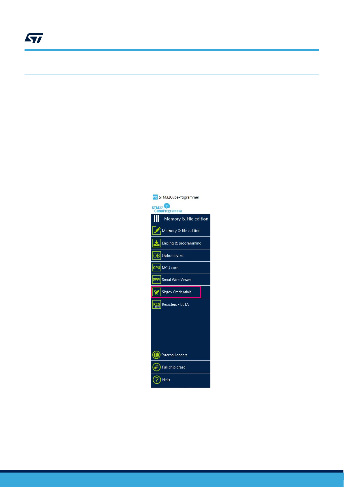
14 Personalization and activation
When compiling and loading the firmware using the default sigfox_data.h, default Sigfox credentials are
loaded in the device. This allows to test the Sigfox device locally in the lab in front of the RSA.
The following steps are needed for the Sigfox device to send data to the Sigfox backend server:
1. Personalization: Every Sigfox device must be loaded with the ID, PAC and private key credentials, that are
necessary to activate the device and send data to the Sigfox data server.
2. Activation: Once the device is personalized, it needs to be recorded by the Sigfox backend server. This step
requires to log-on the Sigfox backend server.
Note: Steps below require STM32CubeProgrammer version 2.6.0 minimum.
14.1 Personalization
As soon as the user connects the STM32WL device, a button Sigfox Credentials is added on the main menu.
Figure 23. STM32CubeProgrammer Sigfox panel button
AN5480
Personalization and activation
AN5480 - Rev 3
page 59/77
Page 60

AN5480
Personalization
After opening the Sigfox Credentials window, the chip certificate is extracted automatically with 136-byte size and
displayed in chip certificate area. This certificate can be saved in a binary file and copied to clipboard to be used
in the ST web interface to get Sigfox credentials (see Section 14.1.1 ). The user have access to the ST web
interface using Open Sigfox page button integrated in the window.
Figure 24. STM32CubeProgrammer Sigfox panel - Getting certificate
AN5480 - Rev 3
page 60/77
Page 61
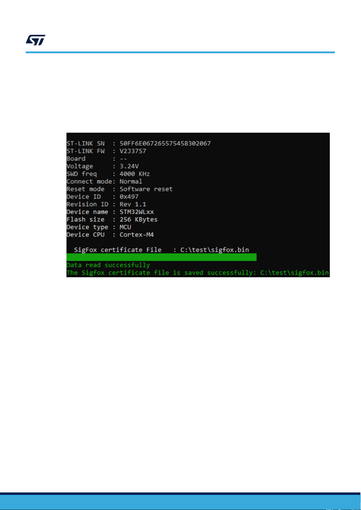
The command line used to save the chip certificate in a binary file:
• Command: -ssigfoxc
• Description: This command allows the user to save the chip certificate to a binary file.
• Syntax: -ssigfoxc <binary_file_path>
• Example: STM32_Programmer_CLI.exe -c port=swd -ssigfoxc /local/user/
chip_certif.bin
Figure 25. STM32CubeProgrammer Sigfox CLI - Getting certificate
AN5480
Personalization
14.1.1 Getting the credentials
ST provides a web interface on my.st.com, where the user can get the sigfox trial credentials.
The credentials are delivered as a zip file containing the following fi
• sigfox_data_XXXXXXXX.h defining the credentials that can be integrated into the application source
code
• sigfox_data_ XXXXXXXX.bin to flash the credentials onto the chip, thanks to STM32CubeProgrammer
AN5480 - Rev 3
page 61/77
Page 62
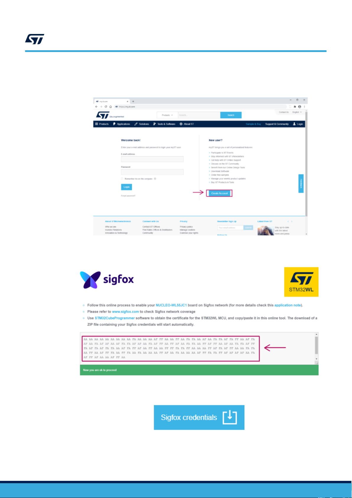
AN5480
Personalization
Follow the steps below to get the credentials:
1. Go to https://my.st.com/sfxp and register on my.st.com to create a specific user account (if not existing yet).
Figure 26. Login on my.st.com
2. Paste the certificate extracted with STM32CubeProgrammer into the form.
Figure 27. Sigfox credential page
3. Click on the download button.
Figure 28. Download button
AN5480 - Rev 3
page 62/77
Page 63
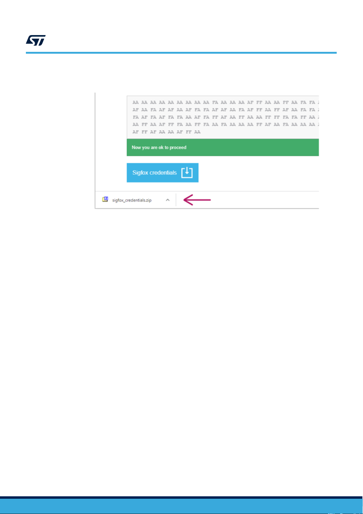
4. A zip file is automatically downloaded on the user computer.
Figure 29. Sigfox_credetentials download
AN5480
Personalization
AN5480 - Rev 3
page 63/77
Page 64

14.1.2 Loading the credentials in the device
As soon as the user gets the Sigfox credential from the ST web interface, the user can load them in the
STM32WL device, at 0x0803 E500, using the Sigfox credential provisioning area in STM32CubeProgrammer.
• Case 1: Binary-Raw:
The binary file returned by the ST web interface must be used. This file must be 48-byte size and is written
at the default address 0x080 3E500.
• Case 2: Binary KMS:
The header file returned by the ST web interface must be used. It is written at the default address
0x0803 E500.
Figure 30. STM32CubeProgrammer Sigfox panel - Flashing credentials
AN5480
Personalization
AN5480 - Rev 3
The command line used to write the credentials in the device is defined as follows:
• Command: -wsigfoxc
• Description: This command allows the user to write the sigfox credentials at the default address
0x0803 E500.
• Syntax: -wsigfoxc <sigfox_credential_file_path> <address>
– <address> is optional (by default 0x0803 E500).
– <sigfox_credential_file_path> can be a binary file (see example 1) or an header file (see
example 2 below).
page 64/77
Page 65

Personalization
Example 1
STM32_Programmer_CLI.exe -c port=swd -wsigfoxc “/local/user/sigfox_data.bin”
0x0803E500
Figure 31. STM32CubeProgrammer Sigfox CLI - Flashing raw credentials
AN5480
AN5480 - Rev 3
page 65/77
Page 66

Example 2
STM32_Programmer_CLI.exe -c port=swd -wsigfoxc “/local/user/sigfox_data.h”
Figure 32. STM32CubeProgrammer Sigfox CLI - Flashing KMS credentials
AN5480
Personalization
AN5480 - Rev 3
page 66/77
Page 67

14.2 Activation
Follow these steps:
1. Use AT$ID?<CR> and AT$PAC?<CR> commands to get Sigfox ID and PAC.
2. Go on https://buy.sigfox.com/activate/ and login.
3. Copy the device ID and PAC into the activate page (see the figure below) and click Next.
AN5480
Activation
Figure 33. Device activation (1/2)
4. The browser loads the page shown below for the example.
Figure 34. Device activation (2/2)
5. The device is now activated on the Sigfox network for 1 year (evaluation activation).
AN5480 - Rev 3
page 67/77
Page 68

AN5480
See the message
14.3 See the message
Go to https://backend.sigfox.com/device/list to see the device listed (click on DEVICE). Data can be sent using
the AT$SF command for example on the terminal. The device sends data to the Sigfox network and messages
are visible on the backend (click on the device Id and the go on the MESSAGES tab).
Caution: The Sigfox backend records a sequence number matching the device sequence number. This sequence number
is incremented on both sides every time a new message is sent/received. The backend accepts messages
only if the device sequence number is greater or equal to the sequence number of the backend. The device
sequence number is stored in the EEPROM emulation of the device on the Flash memory. When the application
is in development, the EEPROM may be erased, for example with the cube programmer. In this case the device
sequence number is reset to 0, then smaller than the sequence number of the backend. Messages are not
displayed but uplinks can still be seen the EVENTS tab. In order to see messages again, press on Disengage
sequence number. This resets the sequence number of the backend, allowing the backend to accept new
messages.
AN5480 - Rev 3
page 68/77
Page 69

15 System performance
15.1 Memory footprint
The values of the figure below have been extracted from the map file using the following configuration of the IAR
compiler (EWARM compiler 8.30.1):
• Optimization: optimized for size level 3
• Debug option: off
AN5480
System performance
Figure 35. Memory footprint
15.2
Real-time constraints
Real-time constraints apply when the Monarch algorithm runs.
15.3 Power consumption
The power consumption has been measured on the STM32WL Nucleo-64 board (NUCLEO-WL55JC) with the
following setup:
• No DEBUG
• No TRACE
In these conditions, the typical consumption in Stop mode is 2 μA.
AN5480 - Rev 3
page 69/77
Page 70

Revision history
Date Version Changes
20-May-2020 1 Initial release.
17-Nov-2020 2
18-Jan-2021 3
AN5480
Table 27. Document revision history
Updated:
• Section 10 Memory section
• Section 11.1 Firmware package
• Intro of Section 11.2 AT modem application
• Section 11.2.3 AT? - Available commands
• Section 11.2.9 ATS410 - Encryption key
• Section 11.2.10 ATS411 - Payload encryption
• Section 11.2.22 AT$RC - Region configuration
• Section 11.3 PushButton application
• Section 11.4 Static switches
• Section 14.1 Personalization
Added:
• Section 12 Dual-core management
• Section 13 Key management services (KMS)
Updated:
• Nucleo-73 corrected in Nucleo-64 in the whole document
• RC5 in Table 3. RF parameters for region configurations
• Intro of Section 5 Sigfox Stack description
• Intro of Section 14 Personalization and activation
• Step 5 of Section 14.2 Activation
AN5480 - Rev 3
page 70/77
Page 71

AN5480
Contents
Contents
1 Overview ..........................................................................2
2 Sigfox standard....................................................................3
2.1 End-device hardware architecture ................................................3
2.2 Regional radio resource .........................................................3
2.3 Rx/Tx radio time diagram ........................................................4
2.4 Listen before talk (LBT) .........................................................5
2.5 Monarch ......................................................................5
2.5.1 Monarch signal description .................................................5
2.5.2 Monarch signal demodulation ...............................................6
3 SubGHz HAL driver ................................................................7
3.1 SubGHz resources .............................................................7
3.2 SubGHz data transfers..........................................................7
4 BSP STM32WL Nucleo-64 boards ..................................................8
4.1 Frequency band ...............................................................8
4.2 RF switch .....................................................................8
4.3 RF wakeup time ...............................................................9
4.4 TCXO ........................................................................9
4.5 Power regulation ...............................................................9
4.6 STM32WL Nucleo-64 board schematic ...........................................10
5 Sigfox Stack description ..........................................................11
5.1 Sigfox certification.............................................................11
5.2 Architecture ..................................................................12
5.2.1 Static view.............................................................12
5.2.2 Dynamic view ..........................................................13
5.3 Required STM32 peripherals to drive the radio.....................................14
6 Sigfox middleware programming guidelines.......................................15
6.1 Sigfox Core library.............................................................15
6.1.1 Open the Sigfox library ...................................................16
6.1.2 Send frames/bits ........................................................16
6.1.3 Set standard configuration ................................................16
AN5480 - Rev 3
page 71/77
Page 72

AN5480
Contents
6.2 Sigfox Addon RF protocol library.................................................18
6.3 Cmac library..................................................................19
6.4 Credentials library .............................................................20
6.5 Monarch library ...............................................................20
7 SubGHz_Phy layer middleware description .......................................21
7.1 Middleware radio driver structure ................................................22
7.2 Radio IRQ interrupts ...........................................................23
8 EEPROM driver ...................................................................24
9 Utilities description ...............................................................25
9.1 Sequencer ...................................................................25
9.2 Timer server..................................................................26
9.3 Low-power functions...........................................................26
9.4 System time ..................................................................28
9.5 Trace........................................................................29
10 Memory section ..................................................................31
11 Application description ...........................................................32
11.1 Firmware package.............................................................32
11.2 AT modem application .........................................................33
11.2.1 UART interface .........................................................33
11.2.2 Default parameters ......................................................33
11.2.3 AT? - Available commands ................................................34
11.2.4 ATZ - Reset............................................................34
11.2.5 AT$RFS - Factory settings ................................................35
11.2.6 AT+VER - Firmware and library versions......................................35
11.2.7 AT$ID - Device ID .......................................................35
AN5480 - Rev 3
11.2.8 AT$PAC - Device PAC ...................................................35
11.2.9 ATS410 - Encryption key..................................................36
11.2.10 ATS411 - Payload encryption ..............................................36
11.2.11 AT$SB - Bit status.......................................................36
11.2.12 AT$SF - ASCII payload in bytes ............................................37
11.2.13 AT$SH - Hexadecimal payload in bytes ......................................37
page 72/77
Page 73

AN5480
Contents
11.2.14 AT$CW - Continuous wave (CW) ...........................................38
11.2.15 AT$PN - PRBS9 BPBSK test mode .........................................38
11.2.16 AT$MN - Monarch scan...................................................39
11.2.17 AT$TM - Sigfox test mode.................................................39
11.2.18 AT+BAT? - Battery level ..................................................41
11.2.19 ATS300 - Out-of-band message ............................................41
11.2.20 ATS302 - Radio output power ..............................................42
11.2.21 ATS400 - Enabled channels for FCC.........................................42
11.2.22 AT$RC - Region configuration..............................................43
11.2.23 ATE - Echo mode .......................................................43
11.2.24 AT+VL - Verbose level....................................................43
11.3 PushButton application.........................................................44
11.4 Static switches................................................................44
12 Dual-core management ...........................................................45
12.1 Mailbox mechanism ...........................................................45
12.1.1 Mailbox multiplexer ......................................................45
12.1.2 Mailbox features ........................................................46
12.1.3 MBMUX messages ......................................................47
12.2 Inter-core memory.............................................................47
12.2.1 CPU2 capabilities .......................................................48
12.2.2 Mailbox sequence to execute a CPU2 function from a CPU1 call ...................48
12.2.3 Mapping table ..........................................................50
12.2.4 Option byte warning .....................................................51
12.2.5 RAM memory mapping ...................................................51
12.3 Startup sequence .............................................................52
13 Key management services (KMS) .................................................54
13.1 KMS key types................................................................55
13.2 KMS keys size................................................................55
13.3 Sigfox keys...................................................................56
13.4 KMS key memory mapping for user applications ...................................56
13.5 How to size the NVM for KMS data storage........................................57
13.6 KMS configuration files to build the application .....................................58
AN5480 - Rev 3
page 73/77
Page 74

AN5480
Contents
13.7 Embedded keys...............................................................58
14 Personalization and activation ....................................................59
14.1 Personalization ...............................................................59
14.1.1 Getting the credentials ...................................................61
14.1.2 Loading the credentials in the device ........................................64
14.2 Activation ....................................................................67
14.3 See the message .............................................................68
15 System performance..............................................................69
15.1 Memory footprint ..............................................................69
15.2 Real-time constraints ..........................................................69
15.3 Power consumption ...........................................................69
Revision history .......................................................................70
Contents ..............................................................................71
List of tables ..........................................................................75
List of figures..........................................................................76
AN5480 - Rev 3
page 74/77
Page 75

AN5480
List of tables
List of tables
Table 1. Acronyms .........................................................................2
Table 2. Region configurations .................................................................3
Table 3. RF parameters for region configurations ....................................................4
Table 4. Timings...........................................................................5
Table 5. Monarch signal characteristics versus RC ...................................................6
Table 6. BSP radio switch ....................................................................8
Table 7. RF states versus switch configuration ......................................................8
Table 8. BSP radio wakeup time ...............................................................9
Table 9. BSP radio TCXO ....................................................................9
Table 10. BSP radio SMPS ....................................................................9
Table 11. Application level Sigfox APIs ...........................................................15
Table 12. Macro channel mapping .............................................................. 17
Table 13. Sigfox Addon Verified library ........................................................... 18
Table 14. Cmac APIs ....................................................................... 19
Table 15. Credentials APIs ................................................................... 20
Table 16. Monarch APIs .....................................................................20
Table 17. Radio_s structure callbacks............................................................22
Table 18. Radio IRQ bit mapping and definition .....................................................23
Table 19. EEPROM APIs .................................................................... 24
Table 20. Sequencer APIs.................................................................... 25
Table 21. Timer server APIs .................................................................. 26
Table 22. Low-power APIs ................................................................... 26
Table 23. Low-power truth table ................................................................ 27
Table 24. Low-level APIs..................................................................... 27
Table 25. System time functions ............................................................... 28
Table 26. Trace functions .................................................................... 29
Table 27. Document revision history ............................................................. 70
AN5480 - Rev 3
page 75/77
Page 76

AN5480
List of figures
List of figures
Figure 1. Timing diagram for uplink only .........................................................4
Figure 2. Timing diagram for uplink with downlink ...................................................4
Figure 3. Monarch beacon...................................................................5
Figure 4. NUCLEO-WL55JC schematic.........................................................10
Figure 5. Static Sigfox architecture ............................................................ 12
Figure 6. Transmission MSC ................................................................13
Figure 7. Reception MSC .................................................................. 13
Figure 8. Memory mapping ................................................................. 31
Figure 9. Package overview................................................................. 32
Figure 10. Tera Term serial port setup...........................................................33
Figure 11. Mailbox overview ................................................................. 45
Figure 12. MBMUX - Multiplexer between features and IPCC channels .................................... 46
Figure 13. Mailbox messages through MBMUX and IPCC channels ......................................47
Figure 14. CPU1 to CPU2 feature_func_X() process................................................. 49
Figure 15. MBMUX communication table......................................................... 50
Figure 16. STM32WL5x RAM memory map.......................................................51
Figure 17. Startup sequence .................................................................52
Figure 18. MBMUX initialization ............................................................... 53
Figure 19. KMS overall architecture ............................................................ 54
Figure 20. KMS static key size ................................................................ 55
Figure 21. KMS dynamic key size.............................................................. 56
Figure 22. ROM memory mapping .............................................................57
Figure 23. STM32CubeProgrammer Sigfox panel button .............................................. 59
Figure 24. STM32CubeProgrammer Sigfox panel - Getting certificate .....................................60
Figure 25. STM32CubeProgrammer Sigfox CLI - Getting certificate ......................................61
Figure 26. Login on my.st.com ................................................................ 62
Figure 27. Sigfox credential page .............................................................. 62
Figure 28. Download button.................................................................. 62
Figure 29. Sigfox_credetentials download ........................................................ 63
Figure 30. STM32CubeProgrammer Sigfox panel - Flashing credentials ...................................64
Figure 31. STM32CubeProgrammer Sigfox CLI - Flashing raw credentials ................................. 65
Figure 32. STM32CubeProgrammer Sigfox CLI - Flashing KMS credentials................................. 66
Figure 33. Device activation (1/2) .............................................................. 67
Figure 34. Device activation (2/2) .............................................................. 67
Figure 35. Memory footprint.................................................................. 69
AN5480 - Rev 3
page 76/77
Page 77

AN5480
IMPORTANT NOTICE – PLEASE READ CAREFULLY
STMicroelectronics NV and its subsidiaries (“ST”) reserve the right to make changes, corrections, enhancements, modifications, and improvements to ST
products and/or to this document at any time without notice. Purchasers should obtain the latest relevant information on ST products before placing orders. ST
products are sold pursuant to ST’s terms and conditions of sale in place at the time of order acknowledgement.
Purchasers are solely responsible for the choice, selection, and use of ST products and ST assumes no liability for application assistance or the design of
Purchasers’ products.
No license, express or implied, to any intellectual property right is granted by ST herein.
Resale of ST products with provisions different from the information set forth herein shall void any warranty granted by ST for such product.
ST and the ST logo are trademarks of ST. For additional information about ST trademarks, please refer to www.st.com/trademarks. All other product or service
names are the property of their respective owners.
Information in this document supersedes and replaces information previously supplied in any prior versions of this document.
© 2021 STMicroelectronics – All rights reserved
AN5480 - Rev 3
page 77/77
 Loading...