

Daughter board for the CR95HF 13.56 MHz transceiver IC
-36
!NTENNATUNING
CIRCUIT
30)5!24BUS
#2(&
Features
■ Ready-to-use printed circuit board including
– CR95HF multi-protocol transceiver IC
– 47 x 34 mm 13.56 MHz inductive etched
antenna and tuning components
– SPI or UART connector for communication
with the host
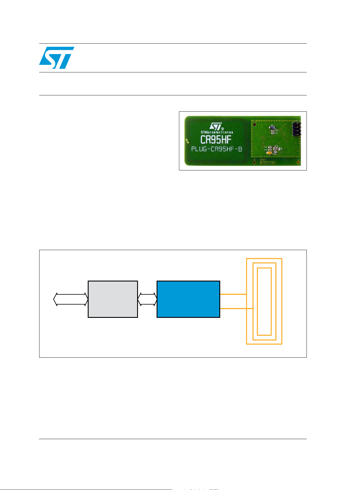
Description
The PLUG-CR95HF-B includes a CR95HF
contactless transceiver, a 47 x 34 mm 13.56 MHz
inductive etched antenna and its associated
tuning components.
The user must connect a host to the board
through the UART or the SPI connector. It allows
PLUG-CR95HF-B
Data brief − production data
to control the 13.56 MHz CR95HF multi-protocol
transceiver IC from the host.
The CR95HF acts as a slave. The host can
configure the transceiver and send SPI or UART
commands.
The PLUG-CR95HF-B board is powered through
the VPS pin.
Figure 1. Functional block diagram
March 2012 Doc ID 022387 Rev 2 1/5
This is information on a product in full production. For further information contact your local STMicroelectronics sales
office.
www.st.com
5
Hardware configuration PLUG-CR95HF-B
-36
33?SOLDERBRIDGE
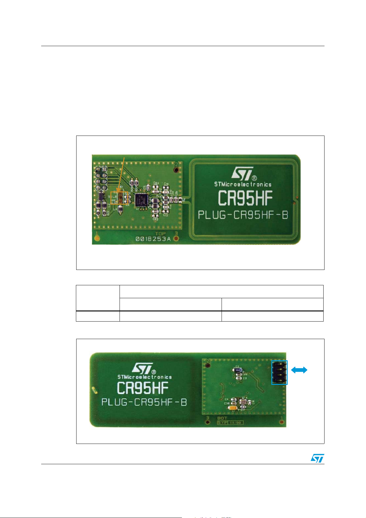
1 Hardware configuration
The PLUG-CR95HF-B daughter board can use either the UART or the SPI as external serial
interface. SS1_0 solder bridge allows to configure the CR95HF to use either the UART or
the SPI serial interface (see Figure 2, and Ta b le 1 ).
Once the solder bridges are configured, the communication mode is automatically enabled
by the CR95HF at power-on.
Figure 2. Top view of the PLUG-CR95HF-B
Table 1. Solder bridge configuration
Communication mode between CR95HF and host
Solder bridge
UART SPI
SSI1_0 GND VPS
Figure 3. PLUG-CR95HF-B connector
-36
2/5 Doc ID 022387 Rev 2

PLUG-CR95HF-B Hardware configuration
Table 2. Description of connector signals
Pin number Signal Description
1 UART_TX and IRQOUT
2 UART_RX and IRQIN
3 SPI_SS
(NSS) SPI slave select
UART transmit pin/interrupt output for CR95HF
UART receive pin/interrupt input for CR95HF
4 SPI_MISO SPI data, slave output
5 SPI_MOSI SPI data, slave input
6 SPI_SCK SPI serial clock
7 VPS and VPS_TX Main power supply/power supply for RF drivers
8 GND Ground
Refer to the CR95HF datasheet for a description of the signals.
Doc ID 022387 Rev 2 3/5
Revision history PLUG-CR95HF-B
2 Revision history
Table 3. Document revision history
Date Revision Changes
13-Feb-2012 1 Initial release.
15-Mar-2012 2
Swapped signal and description for pin 1 and 2 in Ta bl e 2 :
Description of connector signals.
4/5 Doc ID 022387 Rev 2

PLUG-CR95HF-B
Please Read Carefully:
Information in this document is provided solely in connection with ST products. STMicroelectronics NV and its subsidiaries (“ST”) reserve the
right to make changes, corrections, modifications or improvements, to this document, and the products and services described herein at any
time, without notice.
All ST products are sold pursuant to ST’s terms and conditions of sale.
Purchasers are solely responsible for the choice, selection and use of the ST products and services described herein, and ST assumes no
liability whatsoever relating to the choice, selection or use of the ST products and services described herein.
No license, express or implied, by estoppel or otherwise, to any intellectual property rights is granted under this document. If any part of this
document refers to any third party products or services it shall not be deemed a license grant by ST for the use of such third party products
or services, or any intellectual property contained therein or considered as a warranty covering the use in any manner whatsoever of such
third party products or services or any intellectual property contained therein.
UNLESS OTHERWISE SET FORTH IN ST’S TERMS AND CONDITIONS OF SALE ST DISCLAIMS ANY EXPRESS OR IMPLIED
WARRANTY WITH RESPECT TO THE USE AND/OR SALE OF ST PRODUCTS INCLUDING WITHOUT LIMITATION IMPLIED
WARRANTIES OF MERCHANTABILITY, FITNESS FOR A PARTICULAR PURPOSE (AND THEIR EQUIVALENTS UNDER THE LAWS
OF ANY JURISDICTION), OR INFRINGEMENT OF ANY PATENT, COPYRIGHT OR OTHER INTELLECTUAL PROPERTY RIGHT.
UNLESS EXPRESSLY APPROVED IN WRITING BY TWO AUTHORIZED ST REPRESENTATIVES, ST PRODUCTS ARE NOT
RECOMMENDED, AUTHORIZED OR WARRANTED FOR USE IN MILITARY, AIR CRAFT, SPACE, LIFE SAVING, OR LIFE SUSTAINING
APPLICATIONS, NOR IN PRODUCTS OR SYSTEMS WHERE FAILURE OR MALFUNCTION MAY RESULT IN PERSONAL INJURY,
DEATH, OR SEVERE PROPERTY OR ENVIRONMENTAL DAMAGE. ST PRODUCTS WHICH ARE NOT SPECIFIED AS "AUTOMOTIVE
GRADE" MAY ONLY BE USED IN AUTOMOTIVE APPLICATIONS AT USER’S OWN RISK.
Resale of ST products with provisions different from the statements and/or technical features set forth in this document shall immediately void
any warranty granted by ST for the ST product or service described herein and shall not create or extend in any manner whatsoever, any
liability of ST.
ST and the ST logo are trademarks or registered trademarks of ST in various countries.
Information in this document supersedes and replaces all information previously supplied.
The ST logo is a registered trademark of STMicroelectronics. All other names are the property of their respective owners.
© 2012 STMicroelectronics - All rights reserved
STMicroelectronics group of companies
Australia - Belgium - Brazil - Canada - China - Czech Republic - Finland - France - Germany - Hong Kong - India - Israel - Italy - Japan -
Malaysia - Malta - Morocco - Philippines - Singapore - Spain - Sweden - Switzerland - United Kingdom - United States of America
www.st.com
Doc ID 022387 Rev 2 5/5
 Loading...