

Page 1

NON-LINEAR JUNCTION DETECTOR
“NR-CHP”
USER’S MANUAL
201 8
Page 2

CONTENTS
1 Application.…………………………………. 4
2 Function 4
3 NR-CHP complete set………………………. 5
4 Main technical parameters…………................ 6
5
5.1
5.2
5.3
5.4
5.5
Design ……………………………................
Main unit
Accessories …………………………………….…...
Power supply…………………………………..
Charger ……………………………....
Imitator ……………………………………..….…
7
7
9
9
10
11
6 Marking ……………………………..… 11
7 Packing…………………………………………… 11
7
7.1
7.2
7.3
7.4
7.5
NR-CHP operation
Operation condition and restriction
Getting started
NR-CHP workability test
SEARCHING OPERATION
EMERGENCY ACTIONS
12
12
12
14
14
15
9 Battery charging 16
10 Maintenance ………………………………. 19
11 Shipping and storage ………………… 21
12 Certificate of acceptance …………………….. 21
13 Warranty ………………………………….. 32
Page 3

NR-CHP Operation Manual
2
This Manual is intended
for explanation
“NR-CHP” Non-linear Junction Detector
design & principle of operation
as well as directions for its use.
For proper equipment use,
study this Manual in depth.
Page 4

NR-CHP Operation Manual
3
The Device has an open UHF radiator
of electromagnetic energy.
In active mode it represents
a source of active interference
that could cause certain malfunction
of radio-electronic equipment
located in close proximity
It is the responsibility of the User
to comply with the corresponding
Radio Communication Regulations
of the country where ‘NR-CHP’ NLJD
is being used
Page 5

NR-CHP Operation Manual
4
1. APPLICATION
NR-CHP Non-linear Junction Detector (fig. 1) is intended for
searching concealed electronic devices that contain semi-conductor
components.
This Detector can be successfully utilized for suspect person
inspection at a certain check point.
NR-CHP can detect typical target in every operational mode: active,
stand-by or even switched-off.
2. FUNCTION
NR-CHP represents a portable tool that consists of antenna system,
transmitter and two receivers adjusted for double and triple
frequency of transmitter’s probing signal. Both transmitter and
receivers are placed in a Main unit body.
Main unit is fabricated as mono-block in a compact plastic body with
an easy-to-use handle and control panel on the back side of the body.
The UHF probing signal is converted into a poly-harmonic one on
the radiated nonlinear elements (semi-conductive items or corroded
metal-oxide-metal junction) and retransmitted, better say –
‘scattered’ into ambient space.
Retransmitted 2nd & 3rd harmonics of the probing signal are received
and processed simultaneously by receivers.
The received signals levels are reproduced in an audio form and its
volume is proportional to the received signal level while its tone
corresponds to an appropriate harmonic.
If necessary the received signals level can be reduced by ATT
buttons (see Main unit control panel below) and monitored by
corresponding LED indication.
Page 6
NR-CHP Operation Manual
5
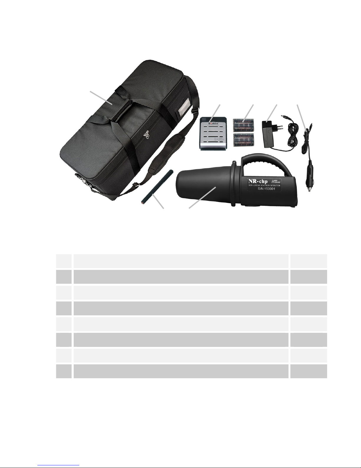
3. NR-CHP COMPLETE SET (table 1)
Table 1
1 NR-CHP Main unit 1
2 Target imitator (test unit) 1
3 Soshine SC-S1 battery charger 1
4 Soshine 18650 rechargeable cells 4*
5 AC power adapter 1
6 Car power adapter
7 Carry bag 11
Operation manual (not shown) 1
* - 2 sets with 2 cells in each
NOTE: rechargeable cells & battery charger can be replaced by any
equivalent version.
1
2
7
3
4 5 6
Fig. 1
NR
-
CHP
complete set.
1- Main unit, 2- imitator (test-unit), 3- charger, 4-
rechargeable cells,
5- AC power adapter, 6- car power adapter, 7- carry bag
Page 7

NR-CHP Operation Manual
6
3. MAIN TECHNICAL PARAMETERS
Target detection range
- SIM card
- Mobile phone
not less 0.10 m
not less 0.15 m
Receiver input signal attenuation
2 steps 10dB each
(0 dB, -10 dB, -20 dB)
Received signal indication
Audio
Operational condition:
Operating temperature
Low limiting temperature
High limiting temperature
Limiting relative humidity
-5°С … +40°С
minus 20°С
+50°С
80% (under +25°С)
Power supply
2 x ‘Soshine’
18650 Li-ion
rechargeable cells 3.7V
Continuous operation time
with one set of fully charged cells
not less 3h*
Weight
Device in a ready for operation state
Complete set in standard packing
1.0±0.1kg
2.0±0.3kg
* - with 2800mAh cells
Page 8
NR-CHP Operation Manual
7
5. DESIGN
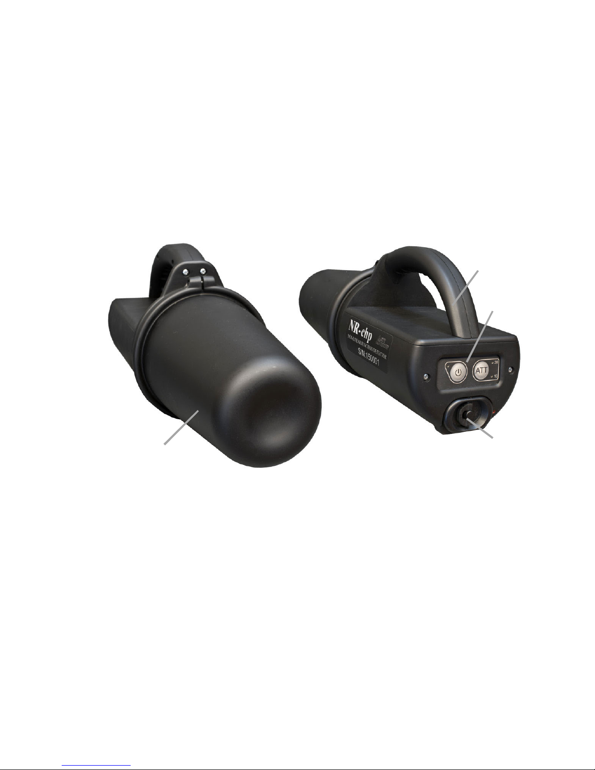
5.1 MAIN UNIT
NR-CHP Main unit represents a handy mono-block comfortable
enough to be held by an operator (fig.3).
The Main unit is equipped with a control panel (3) and a power
supply chamber (4).
1
2
3
4
Fig. 2
NR
-
CHP Main unit.
1- antenna cap, 2-
Main unit handle,
3- control unit panel, 4- battery compartment cover.
Page 9

NR-CHP Operation Manual
8
5.2 NR-CHP back side with
Control unit panel
Control unit consists of membrane keyboard with two nonlocking
buttons and 3 indication LEDs (fig.3)
Button (1) is intended for Detector switching On & Off ,
LED (pos. 2) is used for Detector active mode confirmation.
Button ATT is intended for received signal attenuation value.
Two red LEDs (pos. 3) are used for -10 &-20 dB attenuation level
confirmation.
1
4
2
3
6
5
Fig. 3
NR
-
CHP
Back side.
1- ‘On-Of button’, 2- ‘On’ confirmation LED,
2- 3- (-10dB) &(-20 dB) attenuation confirmation LEDs,
4- attenuator adjustment button,
3- 5- battery compartment, 6- battery compartment lock
Page 10

NR-CHP Operation Manual
9
ACCESSORIES
POWER SUPPLY
Two Soshine 18650 rechargeable sells (fig.5) with 3.7V nominal
voltage and 2800mAh capacity are used for Detector power supply.
The battery compartment for two
Soshine 18650 rechargeable cells
is located on the back side of
Detector housing.
For battery charging Soshine
SC-S1 max Charger (supplied)
is used.
Fig. 4
NR
-
CHP
Battery installation
1- Main unit, 2- battery compartment,
3- rechargeable cells 4- cell holder
1
2
3
4
Fig. 5 Soshine 18650 cells
Page 11

NR-CHP Operation Manual
10
CHARGER
Soshine SC-S1 max Charger (fig. 11) is intended for rechargeable
cells charging. The battery charging is performed in an automatic
mode and does not need any operator’s assistance.
NOTE:
Soshine AC adapter (fig. 6, pos. 3) allows to charge the battery from
the Mains 100 – 240 V, 50/60 Hz.
Soshine DС 12V car adapter (fig.6, pos. 2) is intended for battery
charging from the motocar 12V DC net.
1
2
3
Fig. 6
NR
-
CHP
standard Charger complete set.
1 – Soshine SC-S1 max charger unit
2 – Soshine DС 12V car adapter
3 – Soshine AC power adapter
Page 12

NR-CHP Operation Manual
11
Fig. 7 NR-CHP Imitator (test unit)
Fig.
9 NR
-
CHP
Carry bag
Fig. 8
NR
-
CHP
marking
IMITATOR
Target Imitator (standard test unit) is intended for NR-CHP detector
workability control
Imitator represents highfrequency semi-conductor
diode (2D521A referring to
the Russian classification)
in a Æ14 x 165 mm
solid plastic body.
MARKING
A nameplate with NR-CHP abbreviation and Detector serial number
are located on the transceiver side plate.
One screw slot at the backside
of the Main unit and
the antenna cap shell
screw are also sealed.
PACKING
Complete set of NR-CHP
is packed in a dedicated
shockproof
carry bag (fig.9).
The bag is made of
a durable synthetic fabric
and is equipped with rigid
frame and soft inserts.
Handy grips and a shoulder
strap make its transportation
easy and comfortable.
Page 13

NR-CHP Operation Manual
12
Fig. 10 Rechargeable cells installation
NR-CHP OPERATION
OPERATION CONDITION AND RESTRICTIONS
After long-term exposure to a low temperature keep the device
packed in a standard packing at least 2 hours for evening up its
temperature with the environment.
NOTE: Operating NR-CHP keep corresponding safety measures.
Safety precautions for the open RF emitters:
- Avoid prolonged presence of personnel in a Main lobe of NR-
CHP antenna’ diagram.
NOTE: Probing signal power density at the distance of 1 meter
along the maximum of NR-CHP antenna directional radiation
pattern does not exceed Russian State Standard 12.1.006-84
(Russian State Sanitary Norm) for UHF-equipment serviceman
under continuous 8-hours operation.
GETTING STARTED
Take NR-CHP
components out of
standard packing.
Open battery compartrment at the back side
of the Main unit.
Insert two fresh rechargeable cells (fig.10)
into the cell holder keeping cells polarity
specified on the holder side wall (see an
arrow). Install it into the battery
compartment.
Close the battery
compartment cover and
lock it.
Page 14

NR-CHP Operation Manual
13
1. Push (‘On”) button to switch on Detector (fig.11).
The following mode
is set on default
confirmed by
corresponding LEDs:
– transmitter is on,
– receivers are on,
– input signals
attenuation is at -10 dB
2. Use ATT button to
adjust maximal receiver
sensitivity (fig.12).
3. Aim antenna at various
directions and evaluate
noise background in that
particular point.
Choose the direction
without any noise
reaction for Detector
workability test.
Fig. 11 Detector is switched-on with
-10 dB input signal attenuation
Fig. 12
Detector in a maximal
sensitivity mode
Page 15

NR-CHP Operation Manual
14
Fig. 13 NR-CHP workability test
by means of standard imitator
» 0.5 … 0.7 m
Imitator
NR-CHP WORKABILITY TEST
Place test-unit (imitator) at a chosen direction 0.5…0.7 m from
antenna cap.
At that a tonal signal
should be heard.
Detector is ready for operation
SEARCHING OPERATION
NR-CHP Detector represents a high sensitive radio-electronic
device. Getting started remove from the your pockets and outfit any
items that contains semi-conductive components.
Carry out searching operation with maximal receiver sensitivity.
Use ATT button to activate this mode (see fig. 10 for reference).
The receivers sensitivity is determined by real noise environment
situation right on spot, for instance, by extraneous emission activity
and/or non-lineal junctions that cannot be removed from the area
under control.
USEFUL HINT:
If necessary, depending
on the noise/ interference
situation adjust an
adequate received signal
attenuation by means
of ATT-button.
For instance, -20dB
(see fig.14)
Fig. 14
Page 16

NR-CHP Operation Manual
15
By the end of operation – switch off Detector.
Remove battery from the body and pack complete set in a Carry bag
(fig.9).
EMERGENCY ACTIONS
- In case of the equipment malfunction that cannot be
corrected by the operator, Detector operation should be
stopped.
- If Detector was exposed to an external mechanic,
electromagnetic or climatic impact and temporarily lost its
workability, then before restoring the operation it is
required to carry out its visual checks and a corresponding
functional test referring this Manual.
OPERATION OF THE FAULT DETECTOR
IS NOT ALLOWED.
Page 17

NR-CHP Operation Manual
16
10. BATTERY CHARGING (fig. 15).
Insert 2 or 4 cells (pos.3) into Soshine Charger chamber
(if necessary slide ‘minus’ spring contact)
Pay special attention to cells polarity referring indication on the
charger chamber
Couple AC power adapter or DC 12V car adapter to the socket on a
side wall of the Charger (pos. 2).
Connect AC power adapter to the Mains (100-240V, 50/60 Hz) or
Сar adapter to a corresponding cigarette lighter socket.
After switching on the power the Charger will check every charging
channel operability and initiate the charging mode.
Fig. 15 Soshine SC-S1 max Charger
with 4 cells ready for charging.
1 – LED charging channel indication
2 – Adapter connection socket
3 – Soshine 18650 2800mAh Li-Ion rechargeable
1
2
3
Page 18

NR-CHP Operation Manual
17
Charging mode LED indication (see table 5)
Charger LED indication (Fig. 16, pos.1) Table 5
Charging process status LED light mode
Charger workability self -test 4 x LED light red then
switch over to green
Defective or cells of a wrong type
are installed (for instance Ni-MH,
Ni-Cd and etc.)
Alter green to red
back and forth
Charging mode start Red
80%-90% charge is obtained Blinking green
Fully charged Green
Cell’s wrong polarity Dead
After battery charging completion unplug AC adapter from the
Mains and then from the Charger.
NOTE:
Charging time for Soshine 18650 2800mAh Li-Ion
rechargeable cells with Soshine SC-S1 max charger is as
follows:
4 hours - for 2 cells, 8 hours - for 4 cells
The battery (cells) can be unplugged from the Charger during
any charging stage without any failure to the battery or the
Charger itself.
Page 19

NR-CHP Operation Manual
18
Charger operation precautionary measures
- Do not try to charge primary cells!
That can initiate an explosion and provoke the fire.
Acceptable elements should have an inscription “Rechargeable”.
- Do not block vent holes on the bottom of the charger housing.
For instance, don’t place it on a soft, fleecy surface (carpet,
blanket, seat covering and etc.).
- Charger is intended for indoor use only. Protect the device from
moisture and perspiration water. Do not switch on the charger
and/or power adapters with the obvious presence of moisture
inside the device.
- Do not try to disassemble or modify the device. Do not use it as a
surrogate power source for a certain gadget. The device terminals
are intended for charging appropriate cells only.
- Charger is an electronic device with high frequency circuits and
violent operating current. The wrong operation could cause an
electrical shock.
- Do not leave the charger and/or AC power adapter coupled to the
Mains unattended for a long time. In spite of several protection
circuits used in the charger circuit there is certain probability of
abnormal mode that will cause the fire.
Page 20

NR-CHP Operation Manual
19
11. MAINTENANCE
ATTENTION! IT IS FORBIDDEN
TO DISASSEMBLE DETECTOR!
GENERAL INSTRUCTIONS
The NR-CHP Maintenance should be carried out by the personnel
who studied the Operation Manual and have practical experience of
NLJD usage.
To keep NLJD in fault-free and ready-to-use condition the following
Maintenance are provided:
– Check inspection – performed at the detector acceptance
procedure, preparation for transportation, storage as well as at
periodic testing of serviceability, removal from storage and after
transportation;
– Daily Maintenance – performed after each Detector usage,
transportation or placing in storage;
– Scheduled Maintenance – performed once a year during long-
term storage.
MAINTENANCE ORDER
Check inspection:
– take NR-CHP components, accessories and supporting
documentation from the carry bag;
– check NR-CHP set packaging referring the device packing list;
– verify the seals integrity;
– check NR-CHP components exterior;
– verify labels, signs & marking condition on the device component
housings;
– carry out the device workability test;
– remove the batteries;
– pack NR-CHP components into the carry bag.
Page 21

NR-CHP Operation Manual
20
Daily Maintenance
– use clean rag to remove dirt and dust from external surfaces of the
device components;
– use brush and soup water to clean the carry bag;
– dry the carry bag;
– correct minor paint coating defects (scratches and chipping) of the
device components;
– charge the batteries;
– perform the device workability test;
– remove the batteries;
– pack NR-CHP components into the carry bag.
Scheduled Maintenance
– charge the batteries.
ROUTINE REPAIR
The defective device repair, adjustment and setting-up should be
carried out ONLY by authorized personal at the Manufacturer’s
factory.
Page 22

NR-CHP Operation Manual
21
12. SHIPPING AND STORAGE
NR-CHP can be shipped in a standard packing in a passenger cabin
by any kind of transport.
Prevent Device in standard packing from shock and vibration.
Store packed device under the temperature from +5 up to +40°C and
relative humidity no more than 80 % under +25°C
NOTE: THE BATTERIES SHOULD BE STORED
IN A CHARGED STATE ONLY.
13. CERTIFICATE OF ACCEPTANCE
Non-linear Junction Detector NR-CHP serial No _____________
is in conformity with the Main technical parameters
and is accepted for use.
Seller _______________
Date ________________
Page 23

NR-CHP Operation Manual
22
14. WARRANTY
NR-CHP warranty period is 12 months from the date of purchase.
Manufacturer guarantees normal functioning of the device on the
assumption of the following all requirements of this Manual by the
User and in case of malfunction within the Warranty period
Manufacturer will repair the device free of charge.
Intended service life of the product before discarding is 8 years
including the storage period at the warehouse up to two years.
CUSTOMER COMPLAINTS ARE NOT ACCEPTED
AND WARRANTY MAINTENANCE DO NOT COVER
THE FOLLOWING CASES:
1. Mechanical damage of the device’s units or parts.
2. Traces of independent unauthorized repair and/or warranty
sealing damage.
3. The device’s Works number mismatches to that mentioned in a
Certificate of Acceptance
NOTES:
1. Warranty period does not cover batteries and the Charger.
2: Post-warranty service is accomplished under separate order.
Page 24

NR-CHP Operation Manual
23
FOR NOTES
_______________________________________________________
_______________________________________________________
_______________________________________________________
_______________________________________________________
_______________________________________________________
_______________________________________________________
_______________________________________________________
_______________________________________________________
_______________________________________________________
_______________________________________________________
_______________________________________________________
_______________________________________________________
_______________________________________________________
_______________________________________________________
_______________________________________________________
_______________________________________________________
_______________________________________________________
_______________________________________________________
_______________________________________________________
_______________________________________________________
_______________________________________________________
_______________________________________________________
 Loading...