

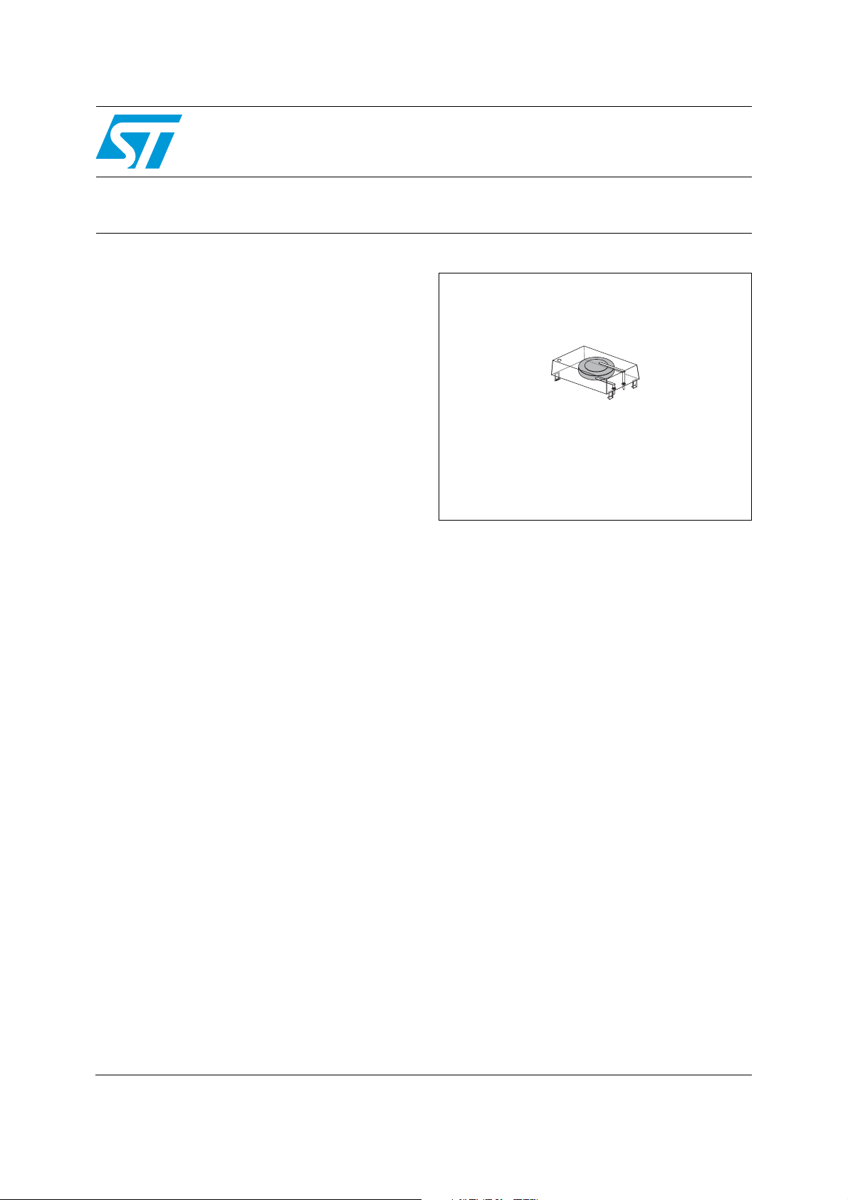
Features
M4Z28-BR00SH
M4Z32-BR00SH
ZEROPOWER® SNAPHAT® (battery)
■ Provides battery backup power for non-volatile
ZEROPOWER
28-pin SNAPHAT
■ Removable battery avoids heat associated with
®
and supervisor devices in the
®
SOIC package
surface-mount process
■ Snaps directly onto surface-mounted
SNAPHAT
■ Choice of battery capacities
®
SOIC
– M4Z28-BR00SH = 48 mAh
– M4Z32-BR00SH = 120 mAh
■ Keyed insertion to insure proper assembly
■ Removable for replacement and proper
disposal
■ Pb-free package
■ Available in tubes or tape & reel
SNAPHAT® (SH)
battery
February 2009 Rev 3 1/16
www.st.com
1

Contents M4Z28-BR00SH, M4Z32-BR00SH
Contents
1 Description . . . . . . . . . . . . . . . . . . . . . . . . . . . . . . . . . . . . . . . . . . . . . . . . . 5
2 Mechanical information . . . . . . . . . . . . . . . . . . . . . . . . . . . . . . . . . . . . . . 6
2.1 Battery characteristics . . . . . . . . . . . . . . . . . . . . . . . . . . . . . . . . . . . . . . . . 7
2.2 UL recognition . . . . . . . . . . . . . . . . . . . . . . . . . . . . . . . . . . . . . . . . . . . . . . 7
2.3 Battery life . . . . . . . . . . . . . . . . . . . . . . . . . . . . . . . . . . . . . . . . . . . . . . . . . 7
2.4 General notes . . . . . . . . . . . . . . . . . . . . . . . . . . . . . . . . . . . . . . . . . . . . . . . 7
3 Maximum ratings . . . . . . . . . . . . . . . . . . . . . . . . . . . . . . . . . . . . . . . . . . . . 9
4 DC and AC parameters . . . . . . . . . . . . . . . . . . . . . . . . . . . . . . . . . . . . . . 10
5 Package mechanical data . . . . . . . . . . . . . . . . . . . . . . . . . . . . . . . . . . . . 11
6 Part numbering . . . . . . . . . . . . . . . . . . . . . . . . . . . . . . . . . . . . . . . . . . . . 13
7 Environmental information . . . . . . . . . . . . . . . . . . . . . . . . . . . . . . . . . . . 14
8 Revision history . . . . . . . . . . . . . . . . . . . . . . . . . . . . . . . . . . . . . . . . . . . 15
2/16

M4Z28-BR00SH, M4Z32-BR00SH List of tables
List of tables
Table 1. Signal names . . . . . . . . . . . . . . . . . . . . . . . . . . . . . . . . . . . . . . . . . . . . . . . . . . . . . . . . . . . . 5
Table 2. Absolute maximum ratings . . . . . . . . . . . . . . . . . . . . . . . . . . . . . . . . . . . . . . . . . . . . . . . . . . 9
Table 3. Operating and AC measurement conditions . . . . . . . . . . . . . . . . . . . . . . . . . . . . . . . . . . . . 10
Table 4. SH – 4-pin SNAPHAT
Table 5. SH – 4-pin SNAPHAT
Table 6. Ordering information scheme . . . . . . . . . . . . . . . . . . . . . . . . . . . . . . . . . . . . . . . . . . . . . . . 13
Table 7. Document revision history . . . . . . . . . . . . . . . . . . . . . . . . . . . . . . . . . . . . . . . . . . . . . . . . . 15
®
housing for 48 mAh battery package mech. data . . . . . . . . . . . . . 11
®
housing for 120 mAh battery package mech. data . . . . . . . . . . . . 12
3/16

List of figures M4Z28-BR00SH, M4Z32-BR00SH
List of figures
Figure 1. Logic diagram . . . . . . . . . . . . . . . . . . . . . . . . . . . . . . . . . . . . . . . . . . . . . . . . . . . . . . . . . . . . 5
Figure 2. SNAPHAT
Figure 3. Battery discharge rates . . . . . . . . . . . . . . . . . . . . . . . . . . . . . . . . . . . . . . . . . . . . . . . . . . . . . 8
Figure 4. DIP extractor tool . . . . . . . . . . . . . . . . . . . . . . . . . . . . . . . . . . . . . . . . . . . . . . . . . . . . . . . . . 8
Figure 5. SH – 4-pin SNAPHAT
Figure 6. SH – 4-pin SNAPHAT
Figure 7. Recycling symbols . . . . . . . . . . . . . . . . . . . . . . . . . . . . . . . . . . . . . . . . . . . . . . . . . . . . . . . 14
®
insertion/extraction forces . . . . . . . . . . . . . . . . . . . . . . . . . . . . . . . . . . . . . . . . . 6
®
housing for 48 mAh battery package outline . . . . . . . . . . . . . . . . 11
®
housing for 120 mAh battery package outline . . . . . . . . . . . . . . . 12
4/16
M4Z28-BR00SH, M4Z32-BR00SH Description
1 Description
The M4Zxx-BR00SH SNAPHAT® top is a detachable lithium power source for ST’s nonvolatile ZEROPOWER
®
surface-mount SOIC (MH) package (28-pin).
The SNAPHAT top contains a lithium battery and is designed to be “snapped on” after the
SOIC is surface mounted on the PC board. The two-piece solution prevents the battery from
being exposed to the high temperatures of the surface mount process.
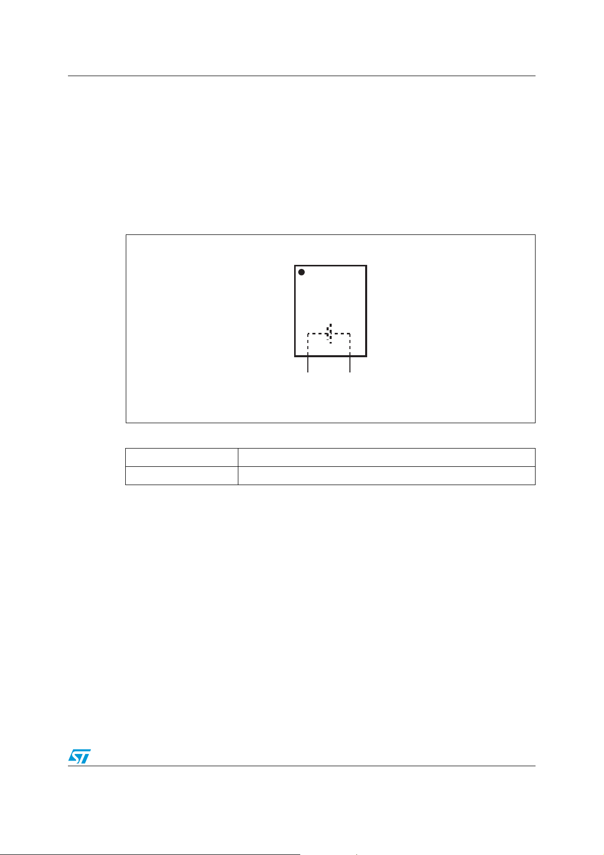
Figure 1. Logic diagram
SNAPHAT
V
BAT–VBAT+
AI02525
Table 1. Signal names
V
BAT–
V
BAT+
Negative voltage
Positive voltage
5/16

Mechanical information M4Z28-BR00SH, M4Z32-BR00SH
2 Mechanical information
Electrical connection to the SOIC is made through two pins that connect to the press fitted
sockets at one end of the SOIC. Critical contact points between the pins and sockets are
gold-plated to resist oxidation. Internally, each socket contains six independent contact
fingers to form redundant connections between the two components. These sockets were
designed to provide high point contact force to provide the lowest possible contact
resistance. The SNAPHAT
onto the ends of the SOIC insuring mechanical and electrical connection even under severe
mechanical shock and vibration. The combined SOIC and SNAPHAT assembly can sustain
shock levels in excess of 100 g without separating. This package also passes variable
frequency testing in accordance with MIL-STD-883, method 2007.2, condition A.
Figure 2 illustrates the affect of repeated insertion and extraction of the SNAPHAT top to the
SOIC. The force required to extract the SNAPHAT, and then to re-insert it, reduces each
time. After four or five extractions, the reduction starts to become unnoticeable and the force
required remains at a fairly constant figure. Typically, though, the SNAPHAT will only need to
be extracted and re-inserted once in its lifetime.
®
top also incorporates four molded-in retaining clips which hold
Figure 2. SNAPHAT
15
12.5
10
7.5
Force (pounds)
5
2.5
0
12345678910
®
insertion/extraction forces
Number of Extractions
Average Insertion
Average Extraction
AI02526
6/16

M4Z28-BR00SH, M4Z32-BR00SH Mechanical information
2.1 Battery characteristics
Figure 3 on page 8 illustrates the lithium coin cell discharge rate for a given load. This
demonstrates the characteristically flat voltage level supplied by the battery until very near
the end of its life. These discharge levels have been greatly accelerated in comparison to
the normal, actual usage.
Note: These batteries contain no mercury (Hg), cadmium (Cd), or lead (Pb).
2.2 UL recognition
The M4Zxx-BR00SH has been recognized by Underwriters Laboratories under their
Component Recognition Program and carries U.L. File Number E89556.
2.3 Battery life
For information on data retention life and battery storage life, please refer to the application
note AN1012.
2.4 General notes
ST has conducted experiments using a manual press which determined that if
approximately 60 pounds of force is applied to the top of the SNAPHAT
and/or die cracks could be induced. As Figure 2 on page 6 specifies, only an average of less
than 13 force-pounds is required for proper insertion. We recommend that no more than 40
pounds of force be applied during SNAPHAT
If a manual press is employed, it is very important that it be calibrated such that it cannot
exceed this limit.
To remove the SNAPHAT
Figure 4). The SNAPHAT top should be grabbed by the narrow end to avoid bending the
pins.
Caution: To avoid draining battery do NOT place SNAPHAT pins into conductive foam.
Caution: To avoid damaging SNAPHAT sockets do NOT wave solder SOIC.
®
top for replacement, a DIP/IC extractor tool should be used (see
®
insertion.
®
, battery damage
7/16

Mechanical information M4Z28-BR00SH, M4Z32-BR00SH
Figure 3. Battery discharge rates
LOAD CHARACTERISTICS Temp: 20°C
3.5
3.0
2.5
2.0
Voltage (V)
Voltage (V)
15kΩ 30kΩ
1.5
1.0
200 400 600 1200 1600 1800
0
LOAD CHARACTERISTICS Temp: 20°C
3.5
3.0
2.5
2.0
15kΩ 30kΩ 50kΩ 100kΩ
1.5
1.0
0
1000 2000 3000 4000 5000 6000
800 1000 1400 2000
Duration (hrs.)
(A)
Duration (hrs.)
(B)
100kΩ
BR1225
BR1632
AI02519
Figure 4. DIP extractor tool
AI02527
8/16

M4Z28-BR00SH, M4Z32-BR00SH Maximum ratings
3 Maximum ratings
Stressing the device above the rating listed in the absolute maximum ratings table may
cause permanent damage to the device. These are stress ratings only and operation of the
device at these or any other conditions above those indicated in the operating sections of
this specification is not implied. Exposure to absolute maximum rating conditions for
extended periods may affect device reliability. Refer also to the STMicroelectronics SURE
Program and other relevant quality documents.
Table 2. Absolute maximum ratings
Symbol Parameter Value Unit
T
T
A
STG
Ambient operating temperature –40 to 85 °C
Storage temperature (VCC off, oscillator off) –40 to 85 °C
Caution: Do NOT wave solder SOIC to avoid damaging SNAPHAT
®
sockets.
9/16

DC and AC parameters M4Z28-BR00SH, M4Z32-BR00SH
4 DC and AC parameters
This section summarizes the operating and measurement conditions, as well as the DC and
AC characteristics of the device. The parameters in the following DC and AC characteristic
tables are derived from tests performed under the measurement conditions listed in the
relevant tables. Designers should check that the operating conditions in their projects match
the measurement conditions when using the quoted parameters.
Table 3. Operating and AC measurement conditions
Parameter M4Z28-BR00SH M4Z32-BR00SH Unit
Nominal battery voltage (VCC)2.82.8V
Nominal battery capacity 48 120 mAh
Battery chemistry Li(CF) Li(CF)
10/16
M4Z28-BR00SH, M4Z32-BR00SH Package mechanical data
5 Package mechanical data
In order to meet environmental requirements, ST offers these devices in different grades of
ECOPACK
specifications, grade definitions and product status are available at: www.st.com.
ECOPACK
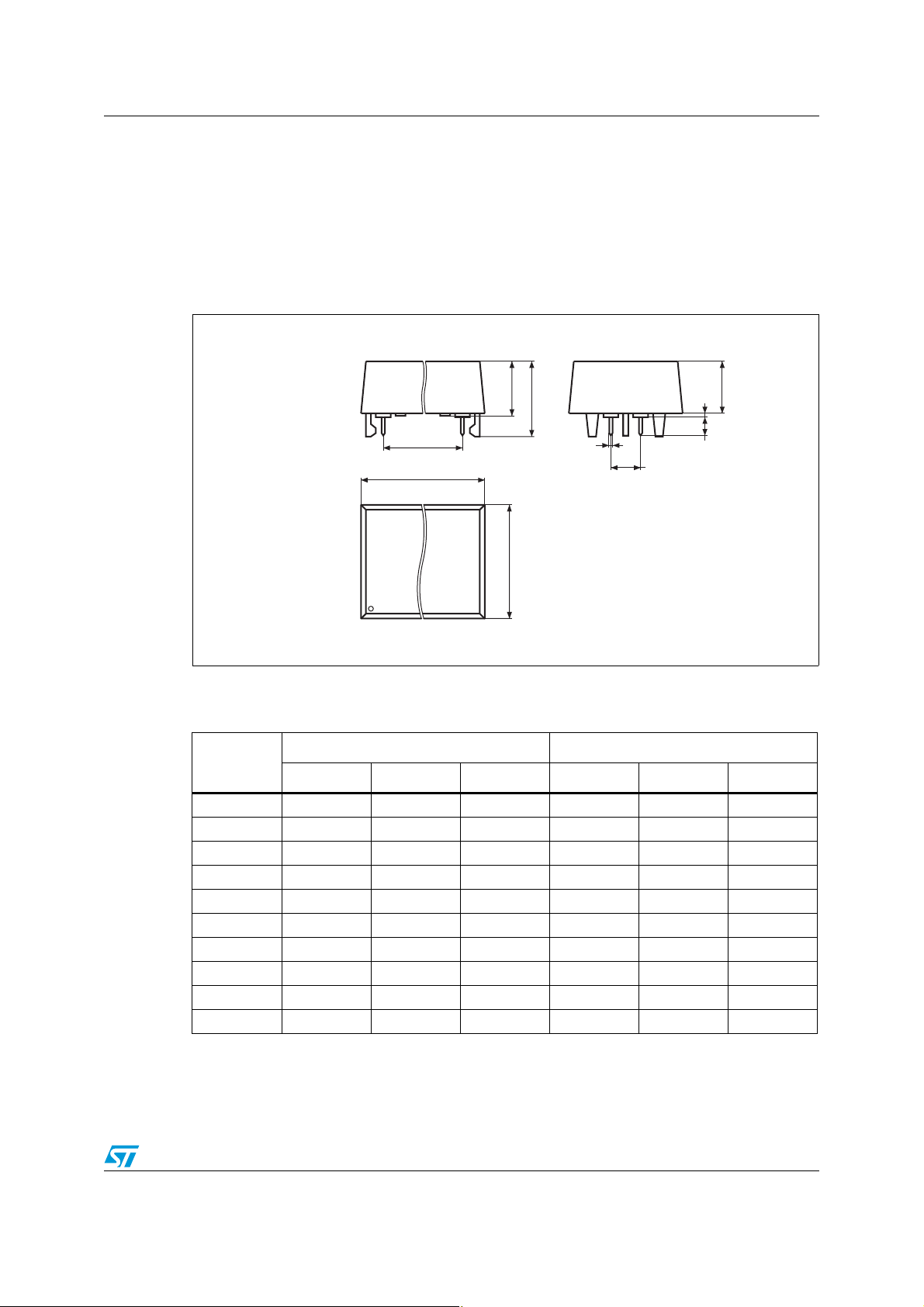
Figure 5. SH – 4-pin SNAPHAT
®
packages, depending on their level of environmental compliance. ECOPACK®
®
is an ST trademark.
®
housing for 48 mAh battery package outline
A3
A2
L
eA
A1
A
B
D
E
eB
SHZP-A
Note: Drawing is not to scale.
Table 4. SH – 4-pin SNAPHAT
Symbol
Typ Min Max Typ Min Max
A 9.78 0.385
A1 6.73 7.24 0.265 0.285
A2 6.48 6.99 0.255 0.275
A3 0.38 0.015
B 0.46 0.56 0.018 0.022
D 21.21 21.84 0.835 0.860
E 14.22 14.99 0.560 0.590
eA 15.55 15.95 0.612 0.628
eB 3.20 3.61 0.126 0.142
L 2.03 2.29 0.080 0.090
®
housing for 48 mAh battery package mech. data
mm inches
11/16
Package mechanical data M4Z28-BR00SH, M4Z32-BR00SH
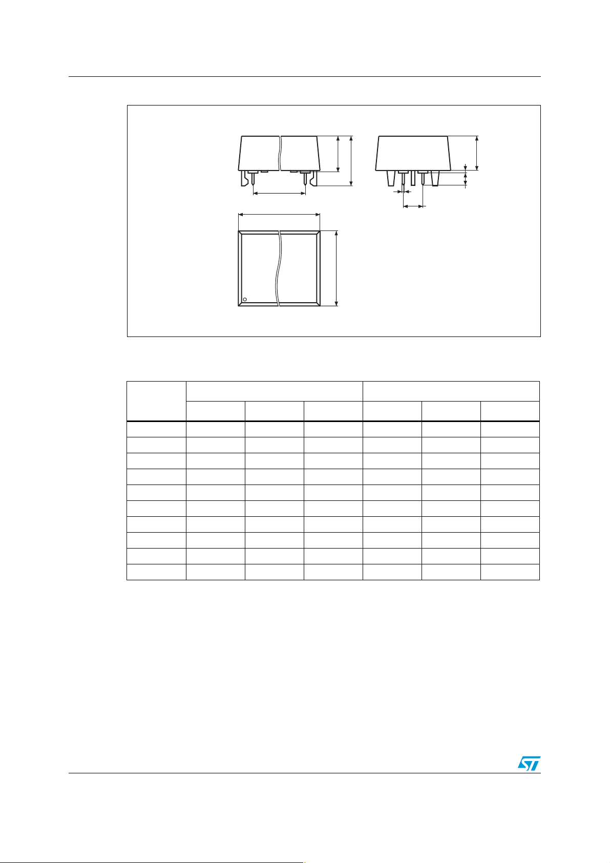
Figure 6. SH – 4-pin SNAPHAT® housing for 120 mAh battery package outline
Note: Drawing is not to scale.
Table 5. SH – 4-pin SNAPHAT
Symbol
Typ Min Max Typ Min Max
A 10.54 0.415
A1 8.00 8.51 0.315 0.335
A2 7.24 8.00 0.285 0.315
A3 0.38 0.015
B 0.46 0.56 0.018 0.022
D 21.21 21.84 0.835 0.860
E 17.27 18.03 0.680 0.710
eA 15.55 15.95 0.612 0.628
eB 3.20 3.61 0.126 0.142
L 2.03 2.29 0.080 0.090
A1
A
eA
D
E
®
housing for 120 mAh battery package mech. data
B
eB
A3
L
SHZP-A
mm inches
A2
12/16

M4Z28-BR00SH, M4Z32-BR00SH Part numbering
6 Part numbering
Table 6. Ordering information scheme
Example: M4Z 28-BR00 SH 1 TR
Device type
M4Z
Battery voltage and capacity
28-BR00 = BR1225, 3 V, 48 mAh
32-BR00 = BR1632, 3 V, 120 mAh
Package
SH = SNAPHAT
Temperature range
®
1 = –40 to 85°C
Shipping method
®
blank = ECOPACK
TR = ECOPACK
package, tubes
®
package, tape & reel
For a list of available options (e.g., speed, package) or for further information on any aspect
of this device, please contact the ST sales office nearest to you.
13/16
Environmental information M4Z28-BR00SH, M4Z32-BR00SH
7 Environmental information
Figure 7. Recycling symbols
This product contains a non-rechargeable lithium (lithium carbon monofluoride chemistry)
button cell battery fully encapsulated in the final product.
Recycle or dispose of batteries in accordance with the battery manufacturer's instructions
and local/national disposal and recycling regulations.
Please refer to the following web site address for additional information regarding
compliance statements and waste recycling.
Go to www.st.com/nvram, then select "Lithium Battery Recycling" from "Related Topics".
14/16
M4Z28-BR00SH, M4Z32-BR00SH Revision history
8 Revision history
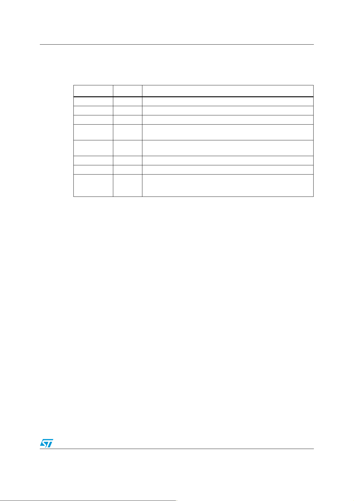
Table 7. Document revision history
Date Revision Changes
Nov-1999 1 First issue
29-May-2001 2 Reformatted
04-Jun-2001 2.1 Basic textual changes from reformatting activity
10-Jul-2001 2.2
21-Jan-2002 2.3
20-Aug-2002 2.4 Update insertion/extraction forces (Figure 2.)
14-Mar-2003 2.5 Add Pb-free note on page 1
26-Feb-2009 3
Remove references to “crystal;” change references to “supervisor” from
controller; clarify temperature characteristics
Change to include crystal accuracy (Ta b l e 3.); add text for SNAPHAT
insertion force tolerance and battery characteristics note
Reformatted document; updated Section 5: Package mechanical data,
Section 2.4: General notes, andTa bl e 6 ; added Section 7:
Environmental information.
®
15/16

M4Z28-BR00SH, M4Z32-BR00SH
Please Read Carefully:
Information in this document is provided solely in connection with ST products. STMicroelectronics NV and its subsidiaries (“ST”) reserve the
right to make changes, corrections, modifications or improvements, to this document, and the products and services described herein at any
time, without notice.
All ST products are sold pursuant to ST’s terms and conditions of sale.
Purchasers are solely responsible for the choice, selection and use of the ST products and services described herein, and ST assumes no
liability whatsoever relating to the choice, selection or use of the ST products and services described herein.
No license, express or implied, by estoppel or otherwise, to any intellectual property rights is granted under this document. If any part of this
document refers to any third party products or services it shall not be deemed a license grant by ST for the use of such third party products
or services, or any intellectual property contained therein or considered as a warranty covering the use in any manner whatsoever of such
third party products or services or any intellectual property contained therein.
UNLESS OTHERWISE SET FORTH IN ST’S TERMS AND CONDITIONS OF SALE ST DISCLAIMS ANY EXPRESS OR IMPLIED
WARRANTY WITH RESPECT TO THE USE AND/OR SALE OF ST PRODUCTS INCLUDING WITHOUT LIMITATION IMPLIED
WARRANTIES OF MERCHANTABILITY, FITNESS FOR A PARTICULAR PURPOSE (AND THEIR EQUIVALENTS UNDER THE LAWS
OF ANY JURISDICTION), OR INFRINGEMENT OF ANY PATENT, COPYRIGHT OR OTHER INTELLECTUAL PROPERTY RIGHT.
UNLESS EXPRESSLY APPROVED IN WRITING BY AN AUTHORIZED ST REPRESENTATIVE, ST PRODUCTS ARE NOT
RECOMMENDED, AUTHORIZED OR WARRANTED FOR USE IN MILITARY, AIR CRAFT, SPACE, LIFE SAVING, OR LIFE SUSTAINING
APPLICATIONS, NOR IN PRODUCTS OR SYSTEMS WHERE FAILURE OR MALFUNCTION MAY RESULT IN PERSONAL INJURY,
DEATH, OR SEVERE PROPERTY OR ENVIRONMENTAL DAMAGE. ST PRODUCTS WHICH ARE NOT SPECIFIED AS "AUTOMOTIVE
GRADE" MAY ONLY BE USED IN AUTOMOTIVE APPLICATIONS AT USER’S OWN RISK.
Resale of ST products with provisions different from the statements and/or technical features set forth in this document shall immediately void
any warranty granted by ST for the ST product or service described herein and shall not create or extend in any manner whatsoever, any
liability of ST.
ST and the ST logo are trademarks or registered trademarks of ST in various countries.
Information in this document supersedes and replaces all information previously supplied.
The ST logo is a registered trademark of STMicroelectronics. All other names are the property of their respective owners.
© 2009 STMicroelectronics - All rights reserved
STMicroelectronics group of companies
Australia - Belgium - Brazil - Canada - China - Czech Republic - Finland - France - Germany - Hong Kong - India - Israel - Italy - Japan -
Malaysia - Malta - Morocco - Singapore - Spain - Sweden - Switzerland - United Kingdom - United States of America
www.st.com
16/16
 Loading...